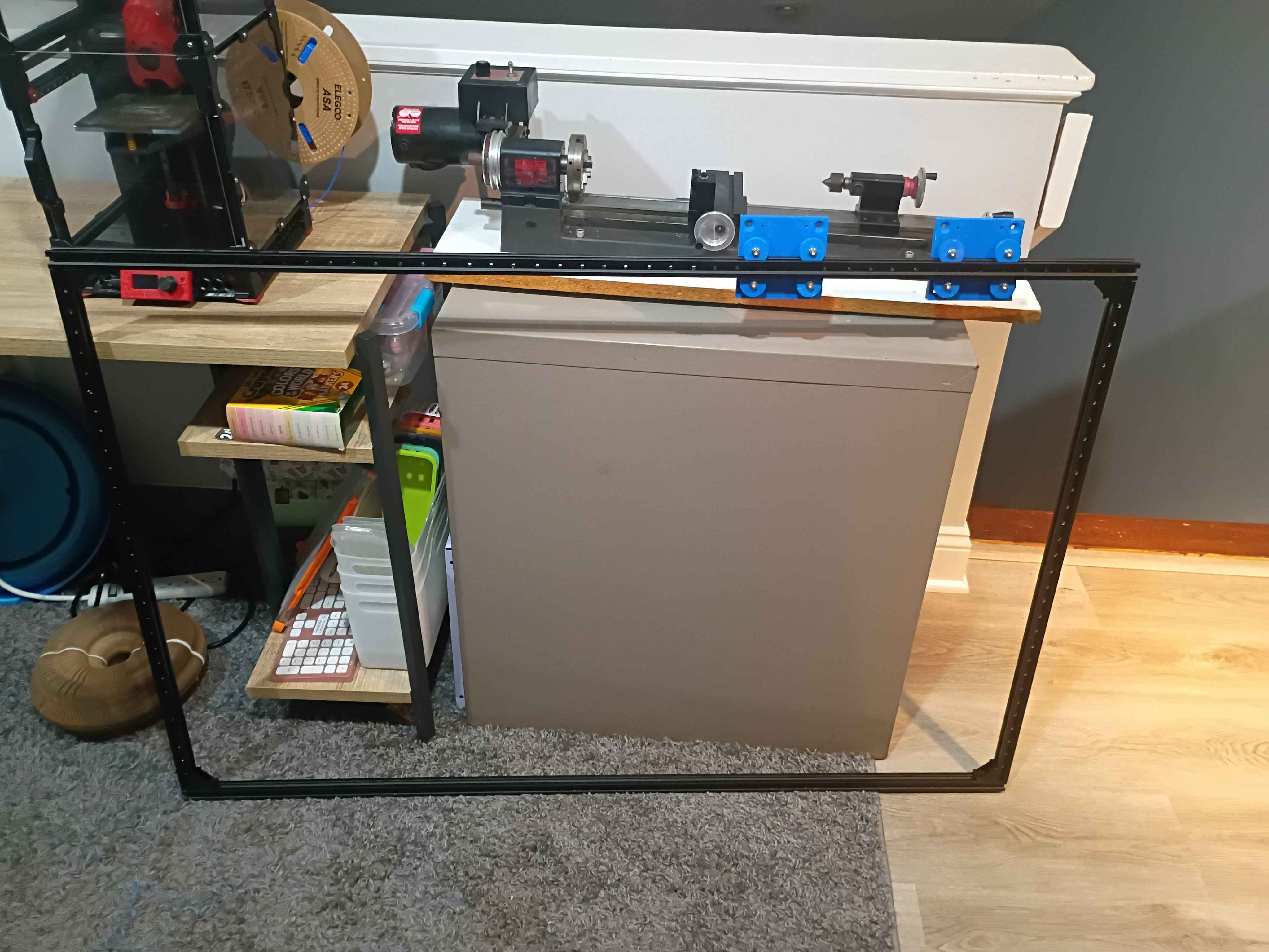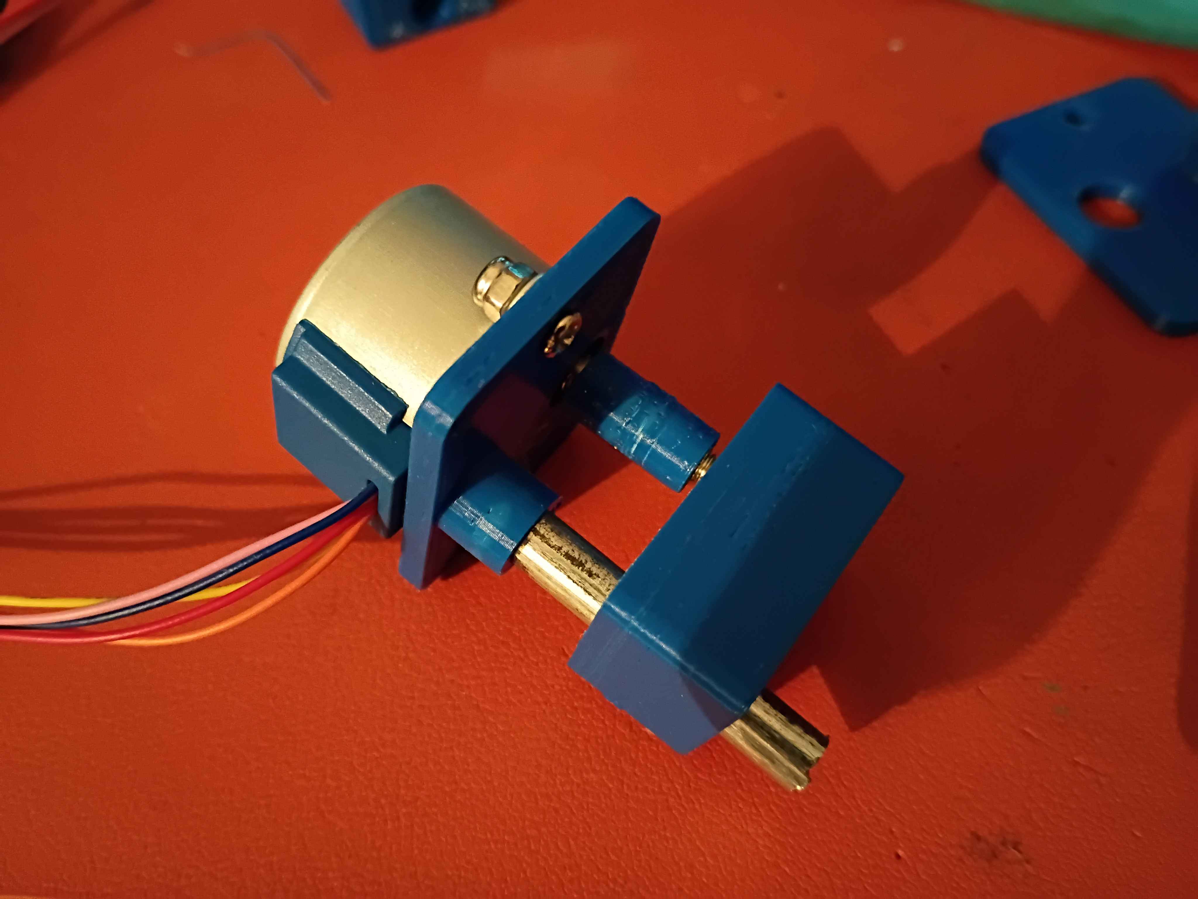
Designed and printed 2 iterations of this short stroke linear actuator that uses an M4 screw, a T slot nut and a stepper motor, but the stroke on this is currently only 2mm, which is not enough to pinch the silicone tubing, and it needs some chassis that contains the tubing as well.
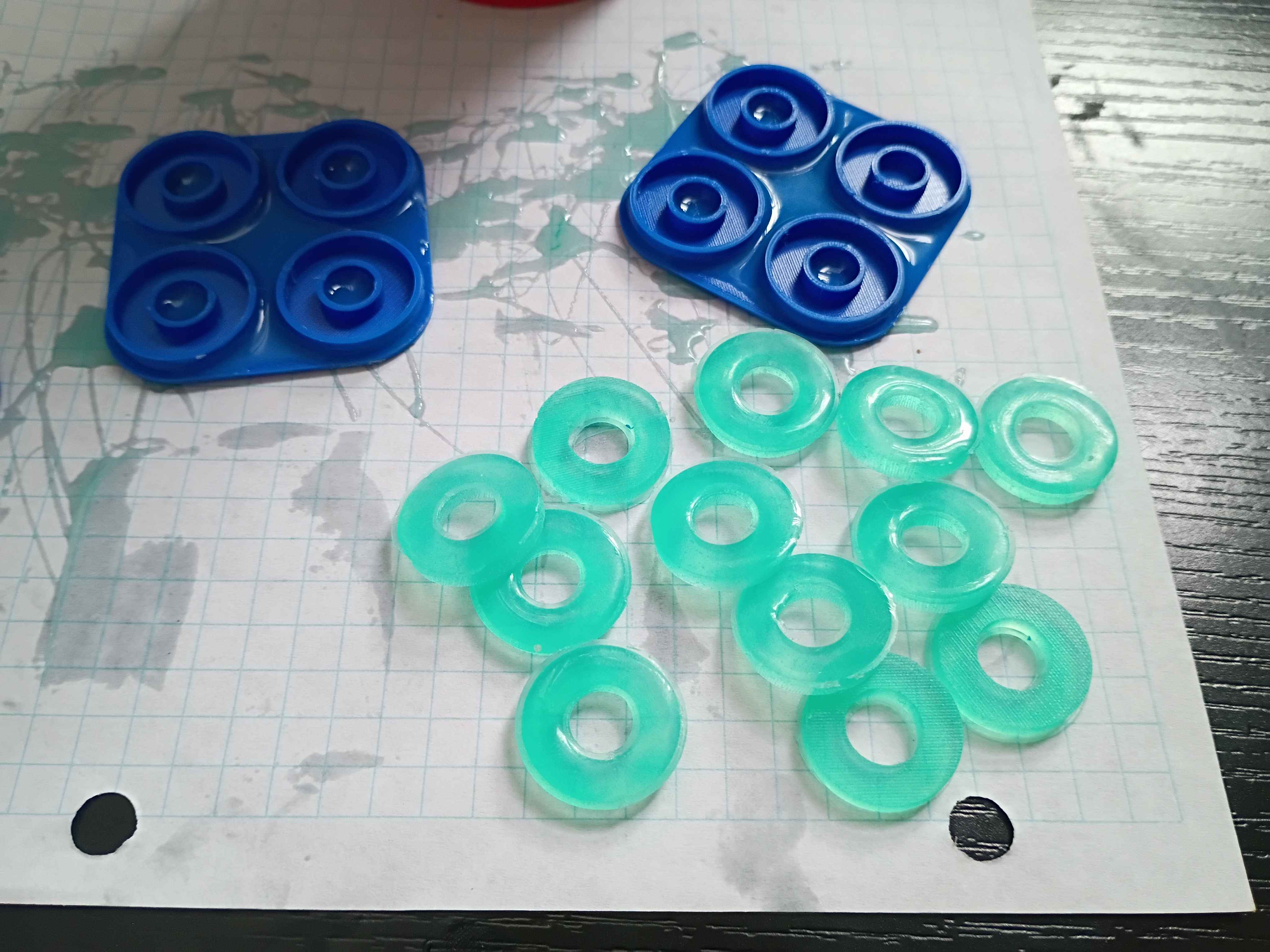
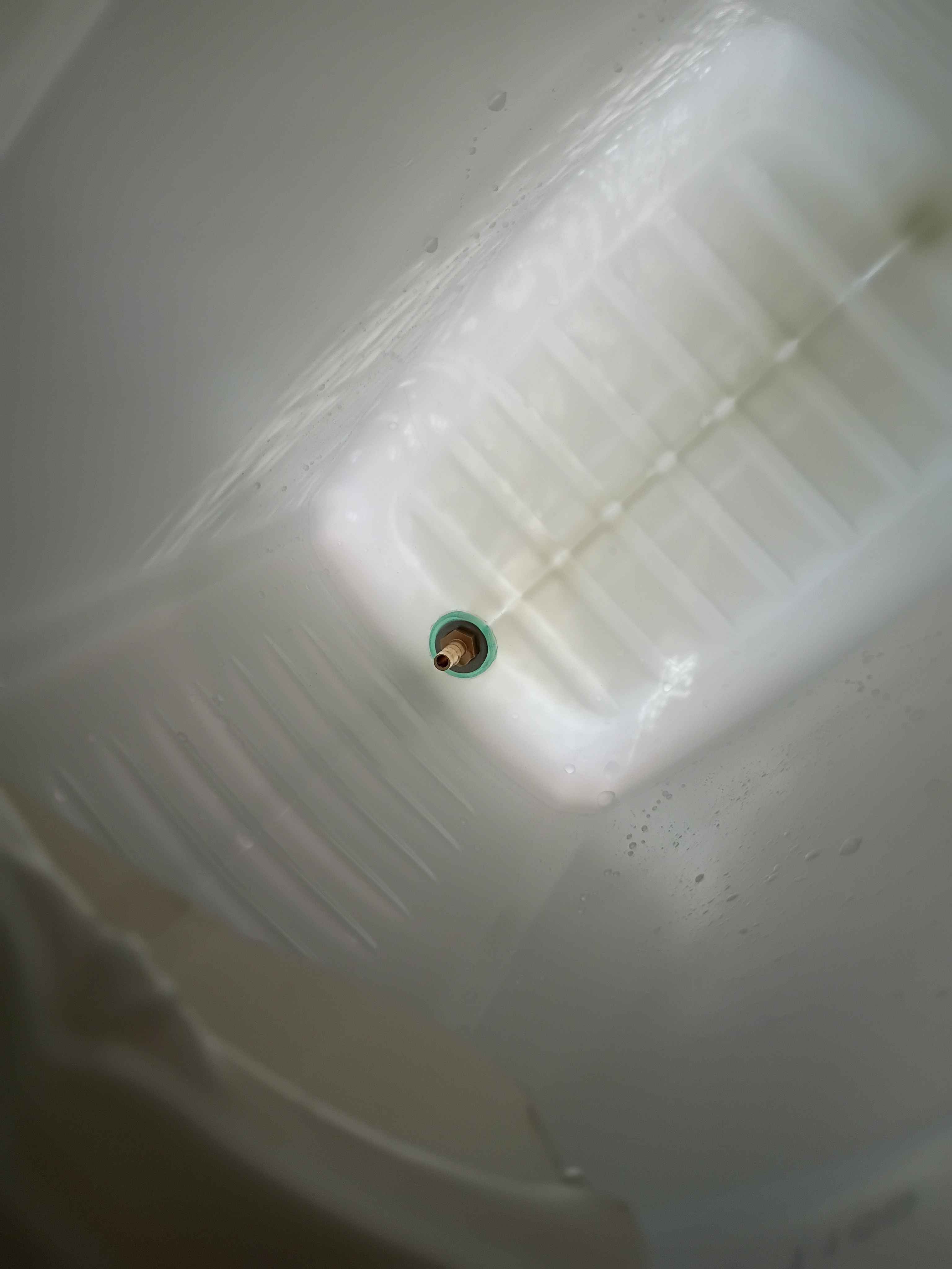
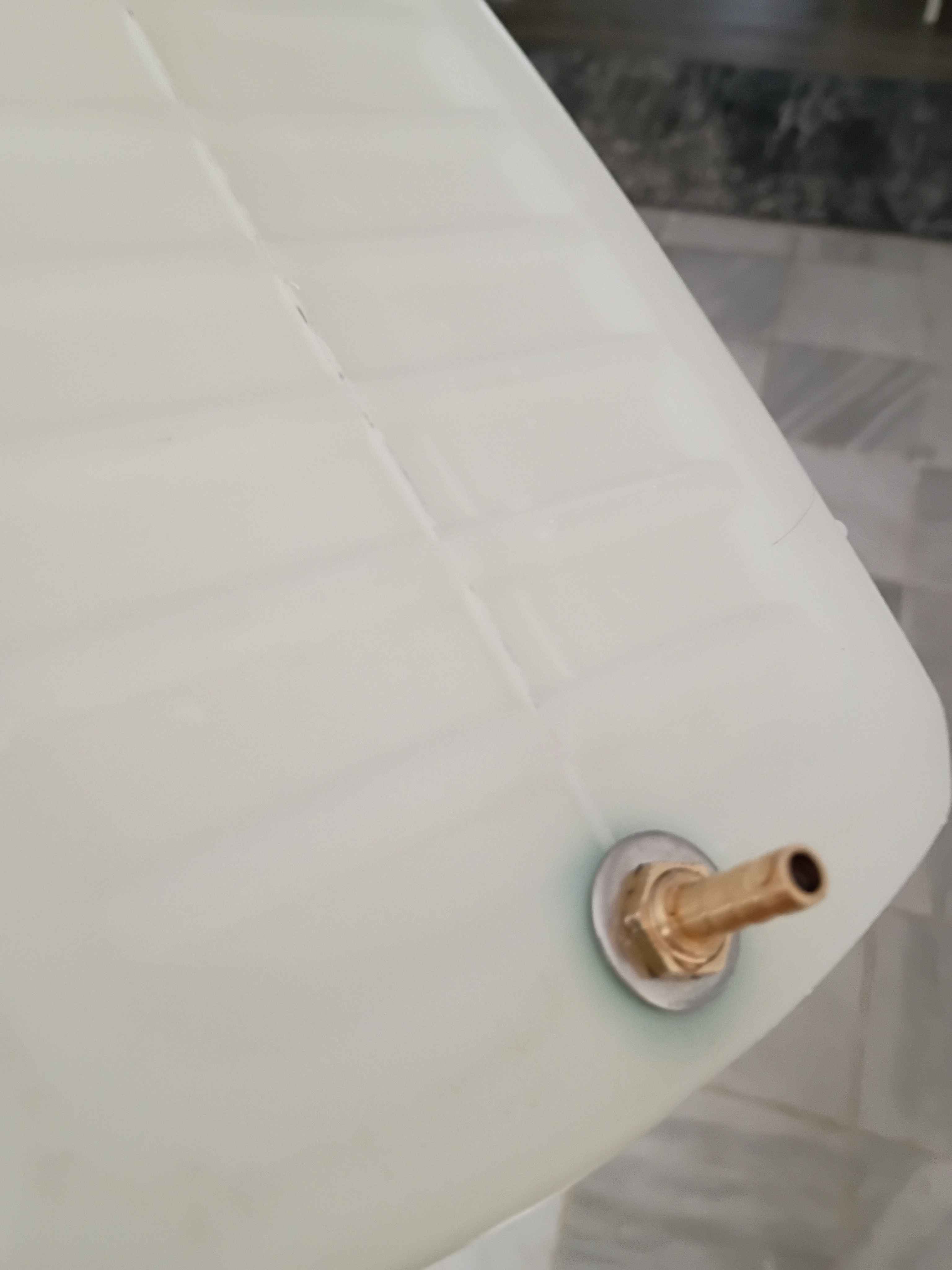
Printed molds and casted silicone gaskets for the water reservoir nipples. 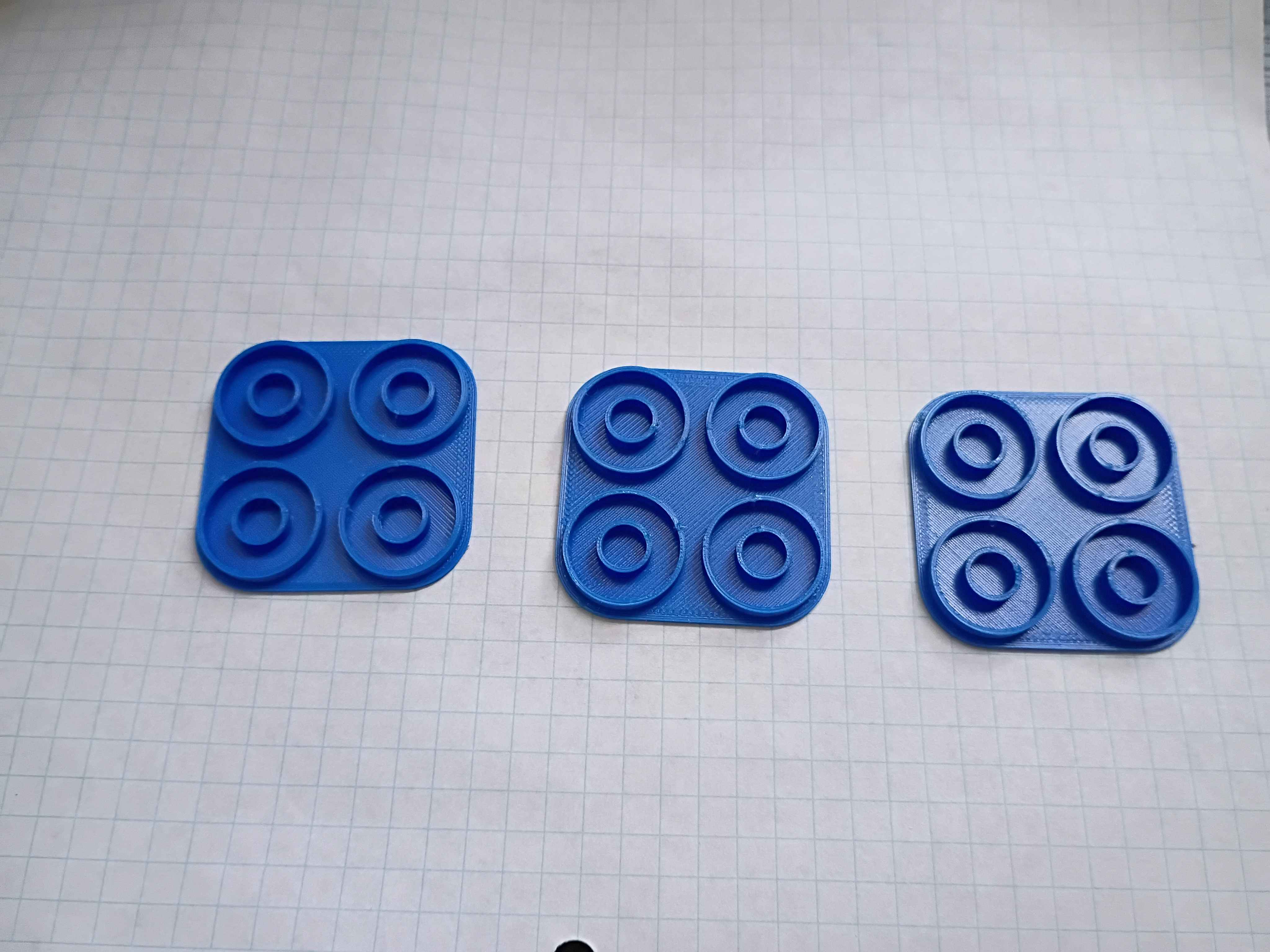
Wrote test code to sweep servo motion. See video.
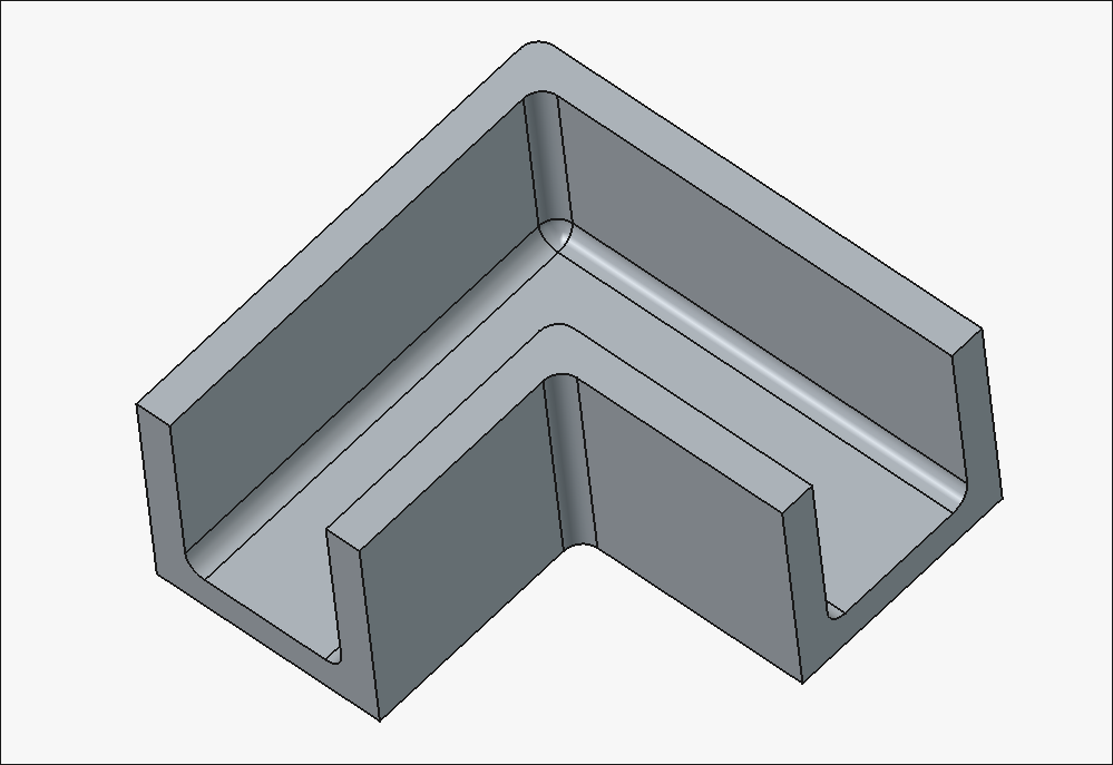
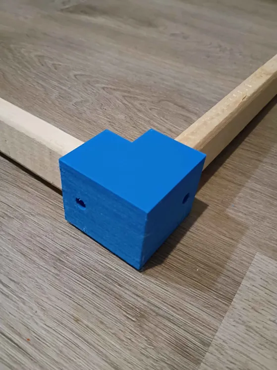
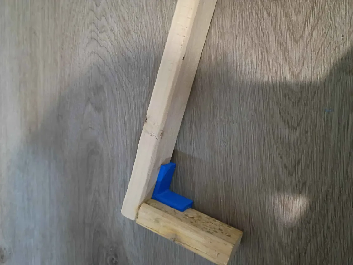
Designed and printed 2 joints for furring strips. These have several planned uses. 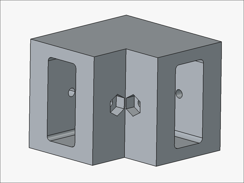
Designed a dock for an Apple Watch charging dongle. It mounts to the 1-inch thick headboard of a bedframe. 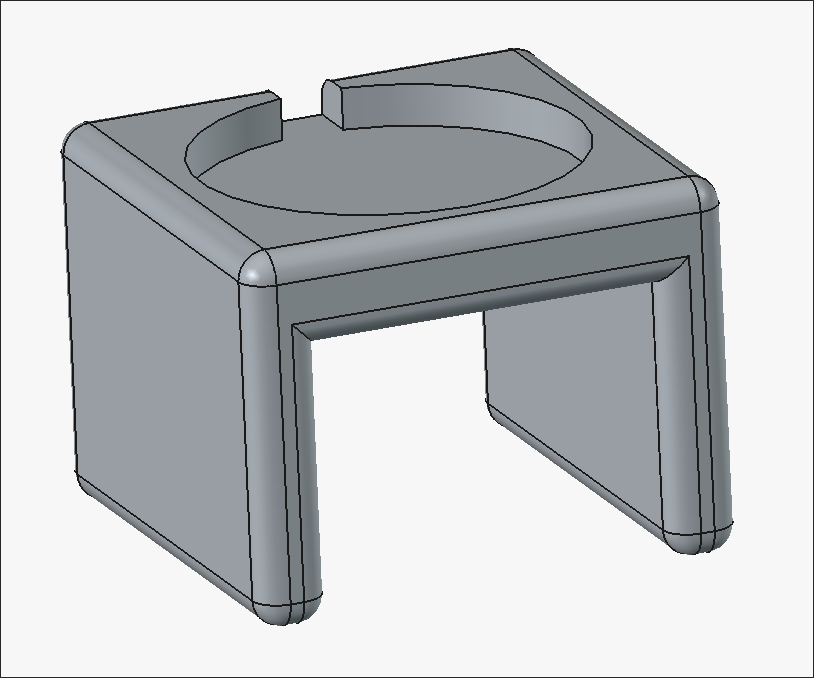
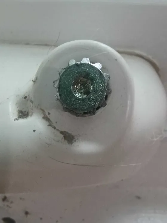
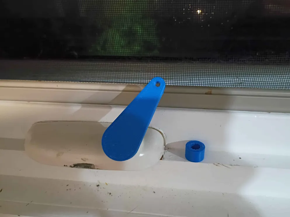
Designed and printed a window crank. It took 2 iterations of the adapter to get it correct. This sets the stage for an automated window control unit. 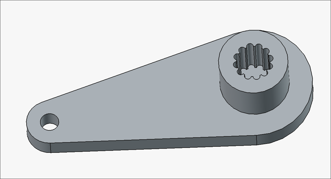
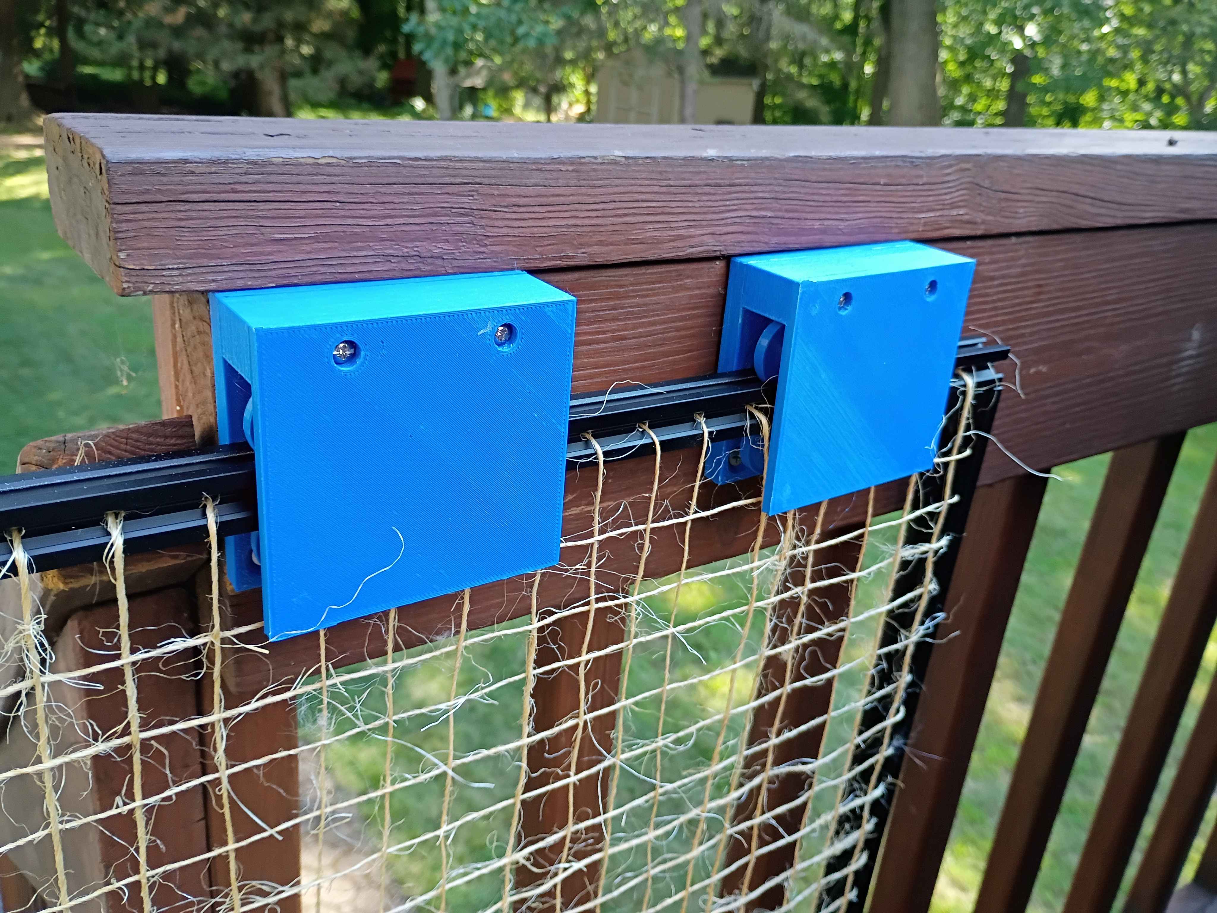
Installed handle. Overall system works very well and is quite smooth to operate. The lightweight nature of the gate is decent but the twine is not especially sturdy, though it would be enough to keep the cat in, which is the intended purpose. The fact that the bottom and cantilevered ends are wholly unsupported does make it seem somewhat fragile. Maybe something could be done to lock the gate in the closed position.
Installed new bracket assembly to raise the entire gate 4mm, which was enough for ground clearance. Also designed and printed this little knob handle that I will install tomorrow. 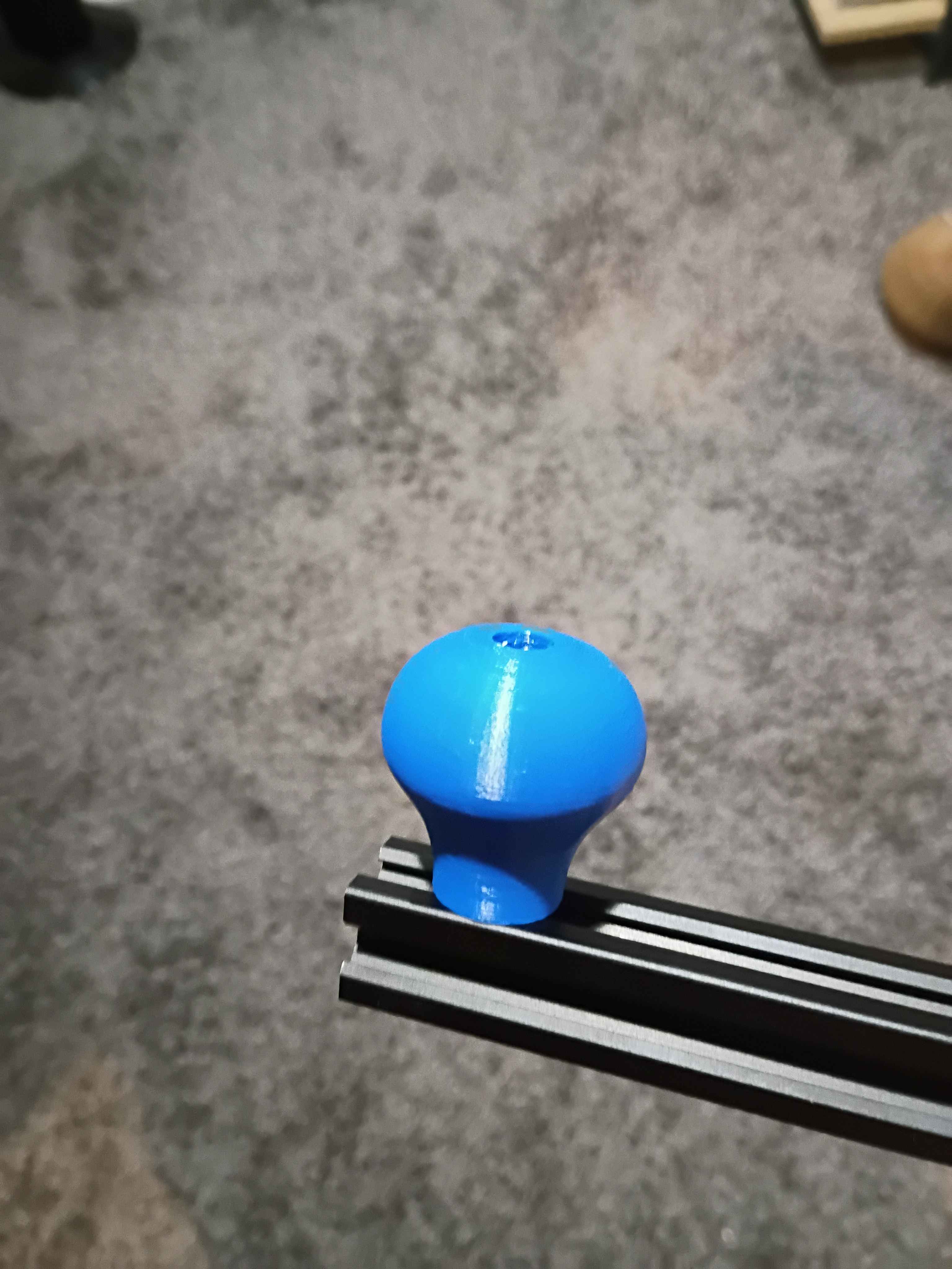
Weaved sisal twine into frame (took a long time) and installed it in on the client's deck. It rubs slightly against the floorboard so I designed and am reprinting the mounting brackets to raise it a few millimeters. In the limit I want to make a handle, some locking feature on the wall end, some soft end cap on the exposed extrusion edge, possibly convert away from 3D-printed ASA to metal components, and make the actual gate a bit more sturdy by running some reinforcement stringers (maybe steel cable). 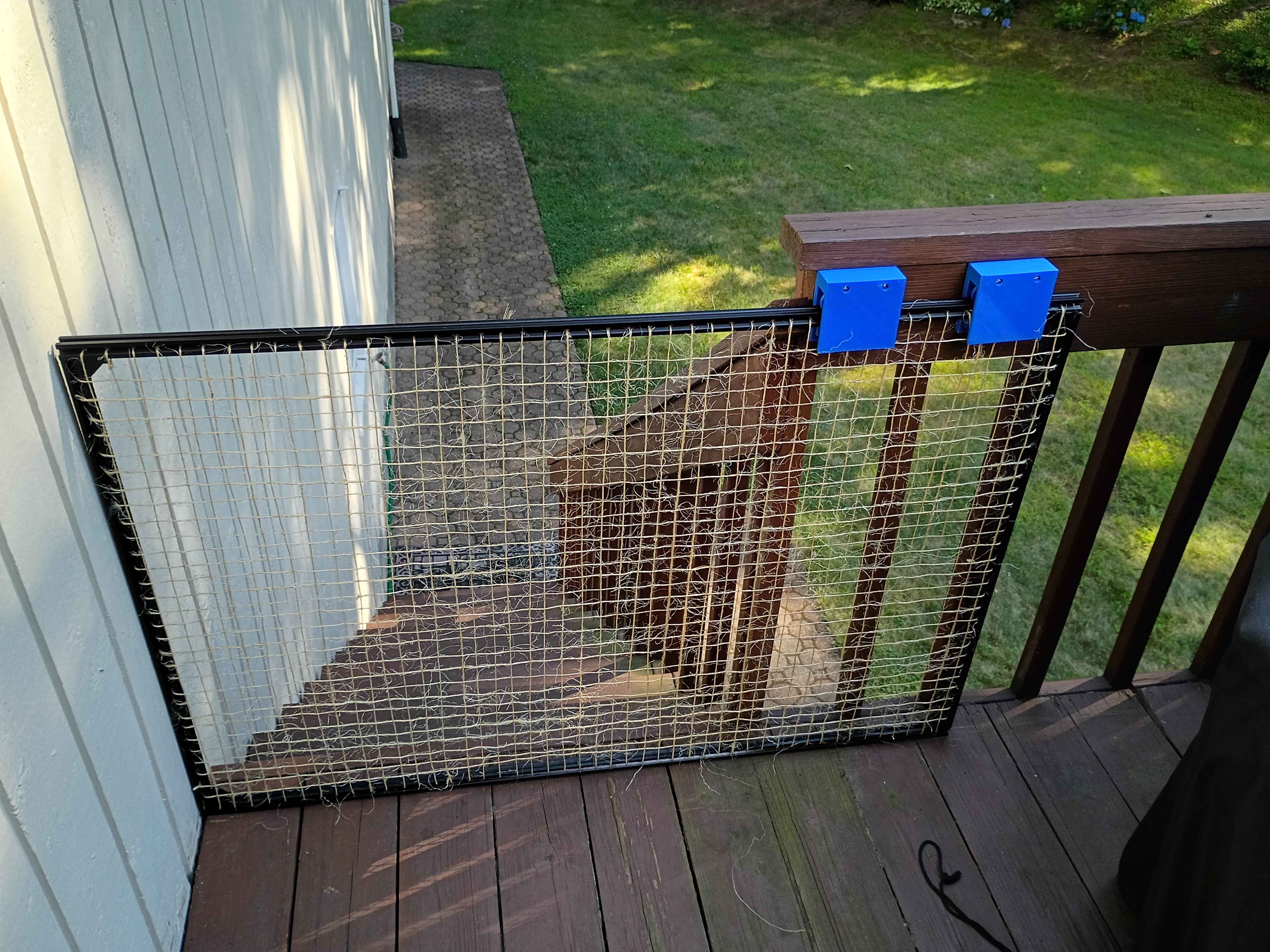
Cut 2020 aluminum extrusion for the gate. Drilled holes every inch along each bar for eventual threading of wire. Assembled the entire frame along with the carriage assemblies.