Created barebones documentation entry in project repository.
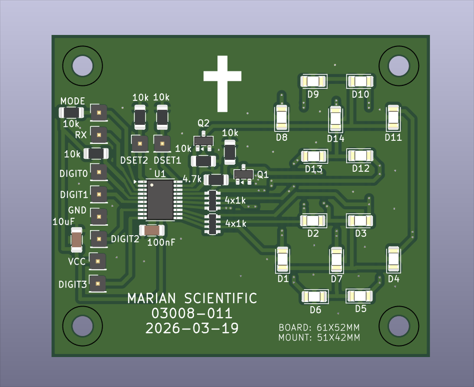
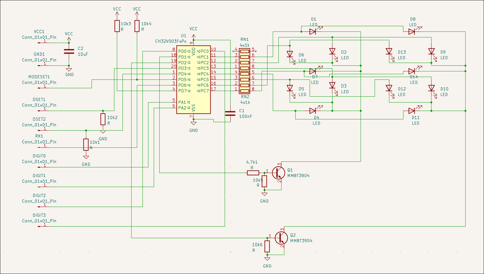
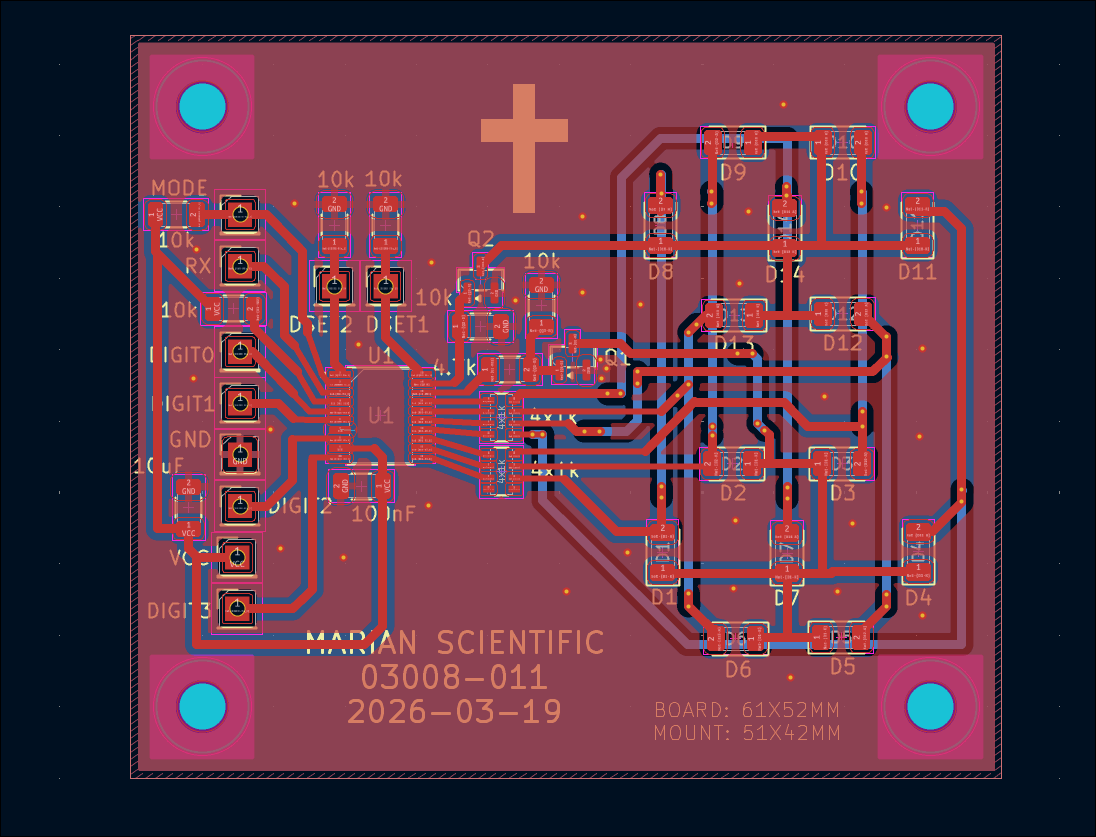
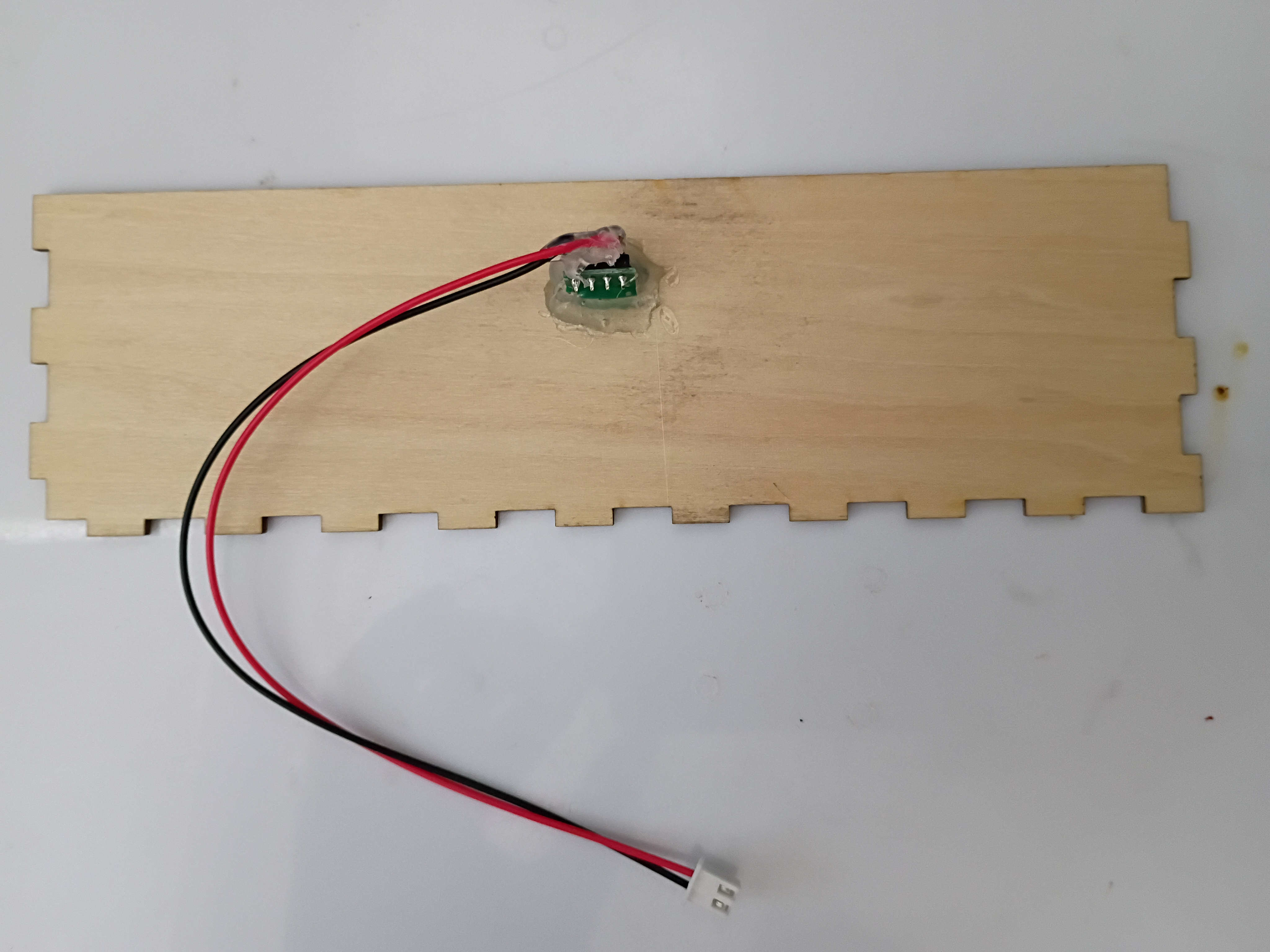
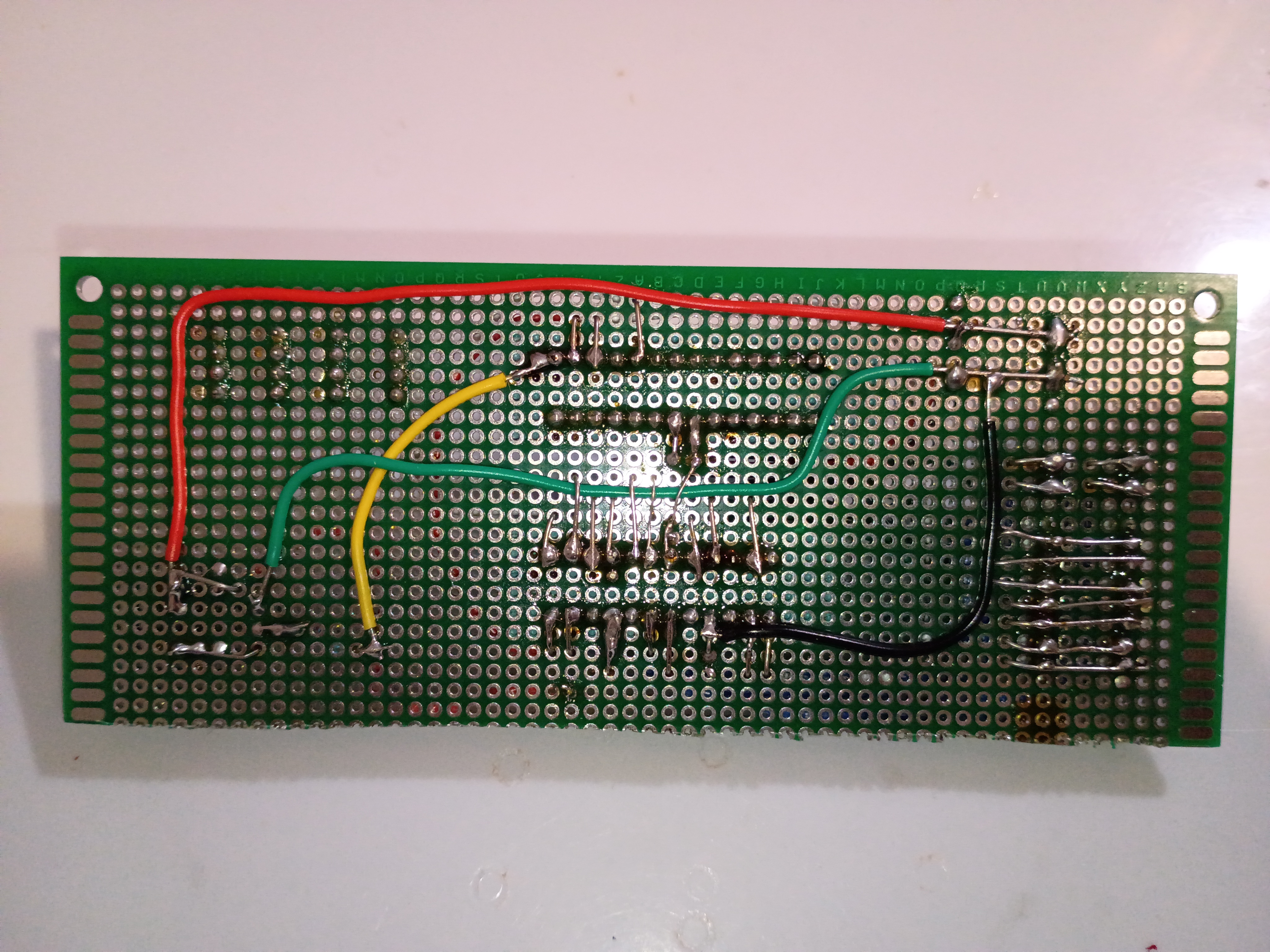
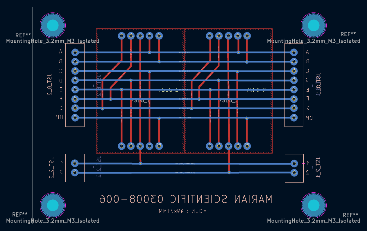
Designed double 7-segment driver and controller circuit (03008-011), can take inputs either from RX or binary digits using MODESET and LATCH pins. The 7 segments are constructed from discrete LEDs, set in slightly opaque epoxy resin.
Recorded final video of manipulative working. The prototype will be used as a template for a future productionization effort and, afterwards, permanently donated to the test classroom.
Tested the project with 6-7 year olds, and it was a massive hit. Kids were fighting over the 3 magnetic input blocks, and I kept a half-dozen or so busy for around 15 minutes during dismissal. They thought it was professionally-made. I think one factor about the manipulative that they enjoyed was the tactile nature, which is not something familiar to them in an age of touchscreen-everything. 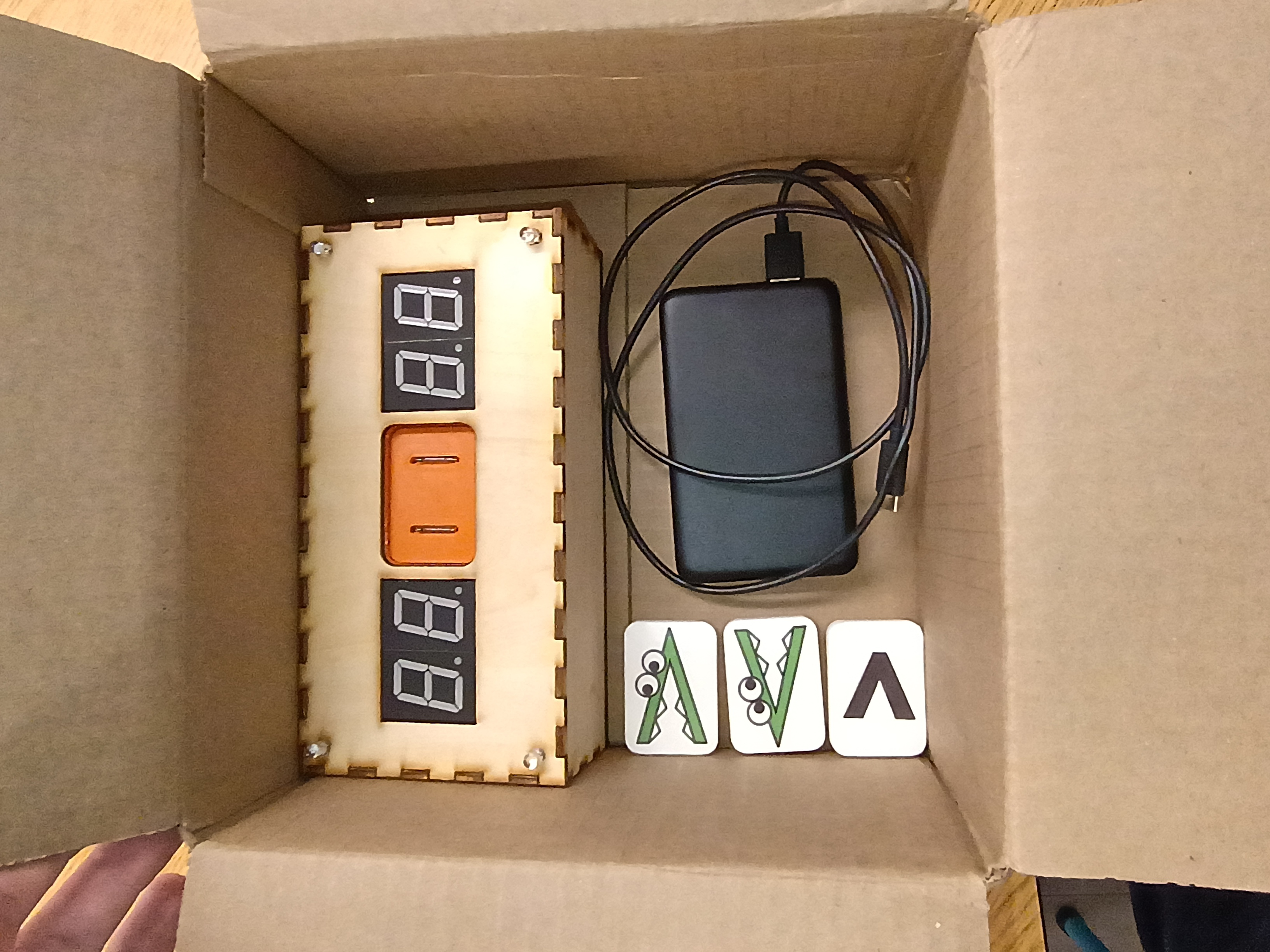
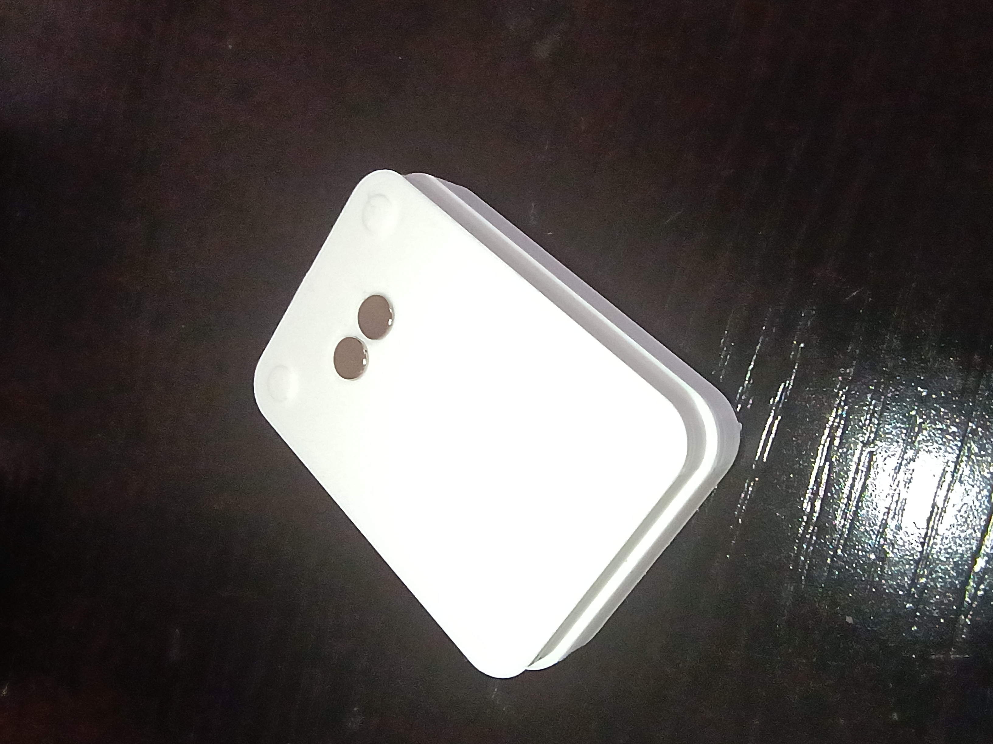
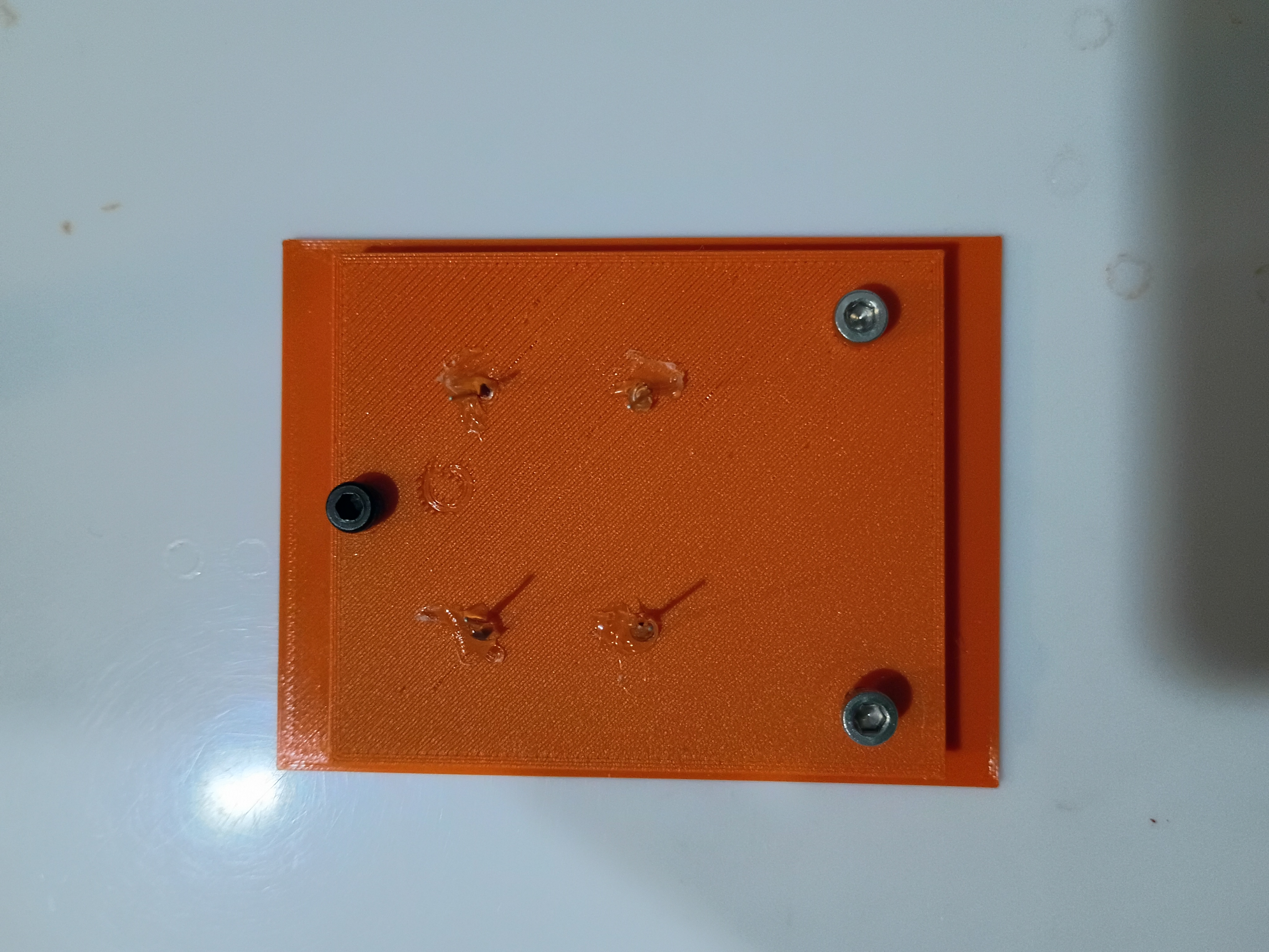
Project complete 3 days early. Made final updates to the full project code to fix the RNG and the intermittent failed 7-segment initialization. Also somehow the power draw is now high enough that it doesn't seem to automatically shut off the USB power bank, though the power bank still reads 100% after 3 days of testing. Designed a new 03008-010 input block with standoffs and a bigger grip area. See latest CAD. Printed two versions in new white PLA and applied the 'Alligreater' image (one mirrored) to the front with a glossy transparent parent sticker. Will test this device with the children tomorrow. 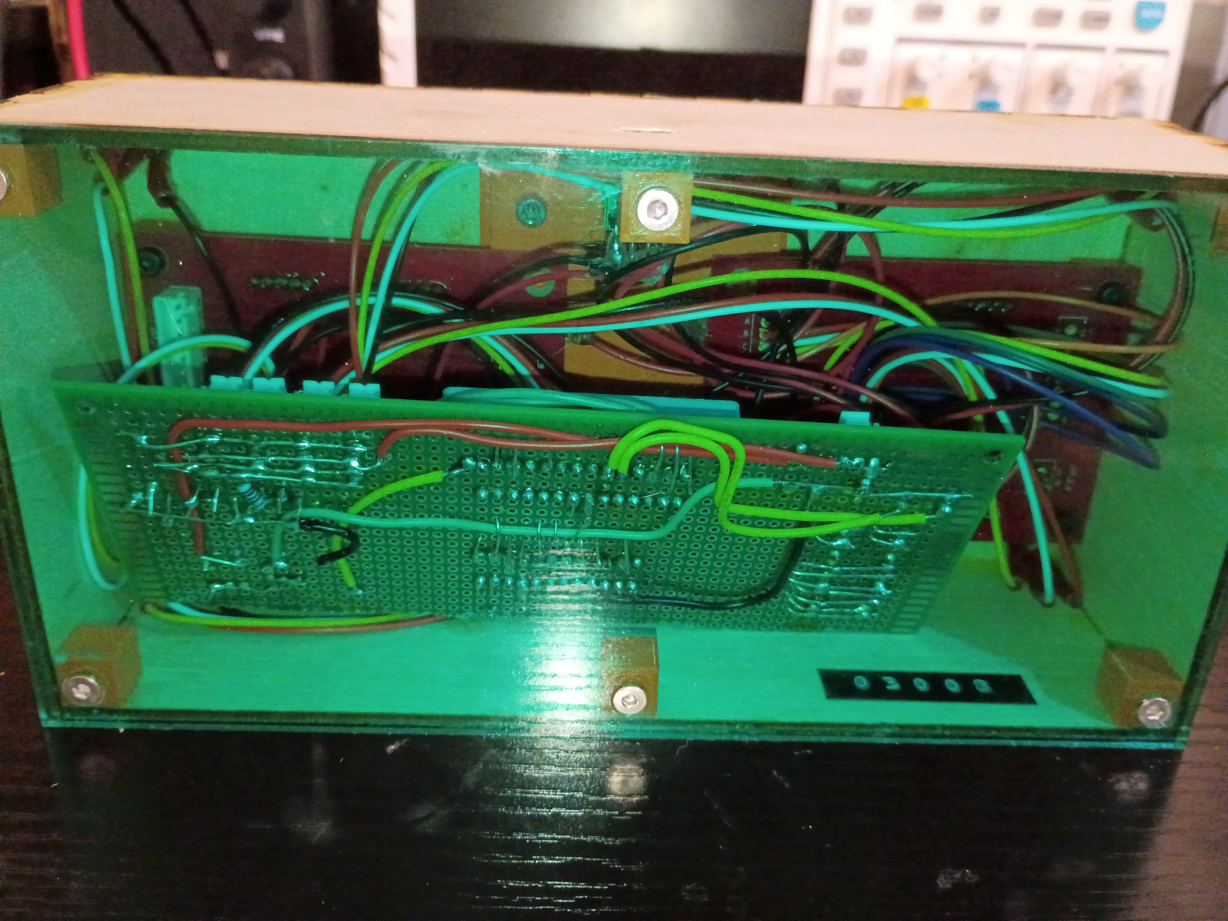

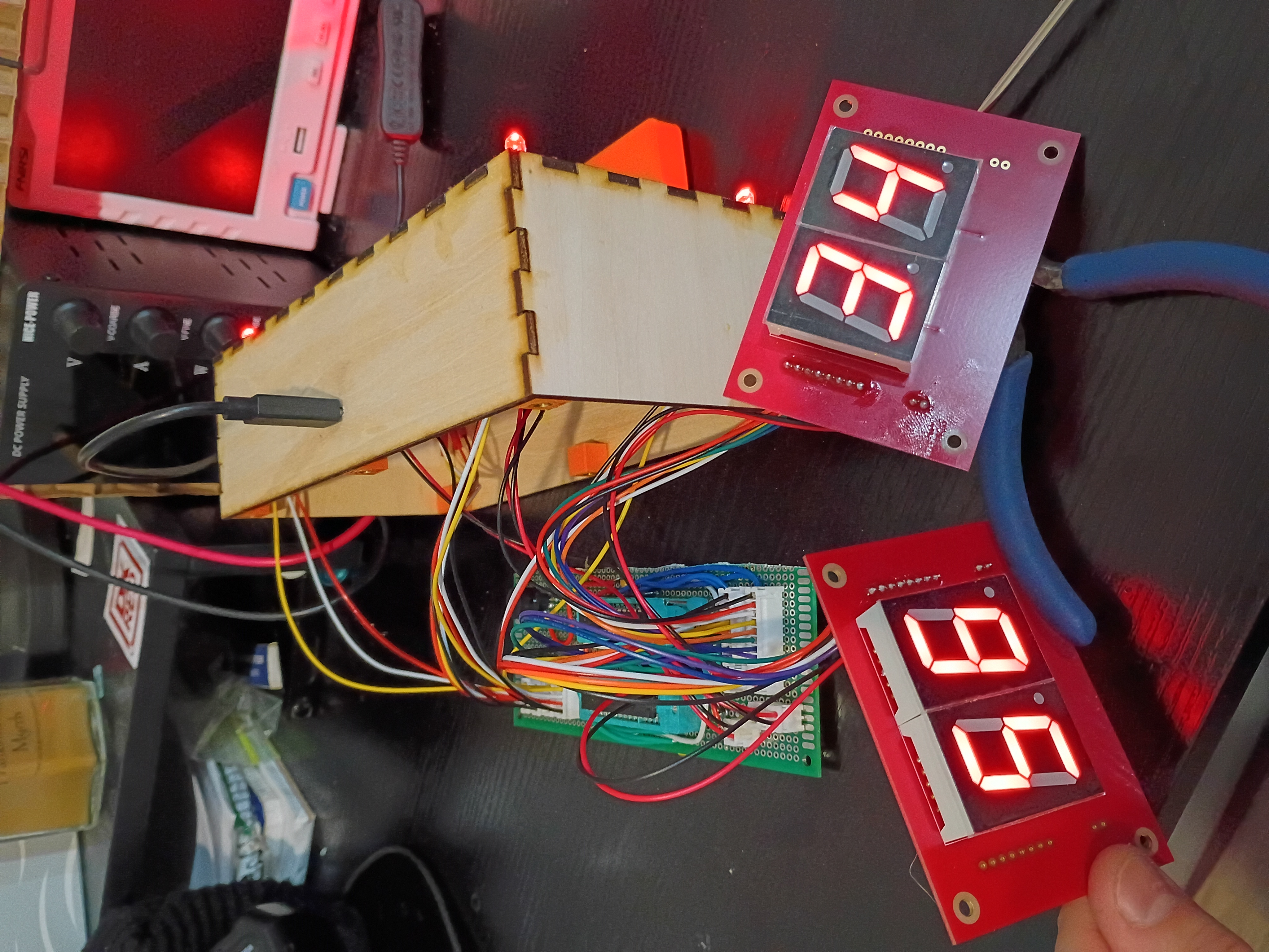
Updated the full project code. Entire project essentially works - including the buzzer, RNG, LEDs, magnetic inputs, etc. See video of it in action. Still needs an improved input block and there is still a glitch where it sometimes initializes with 88/88 on the displays.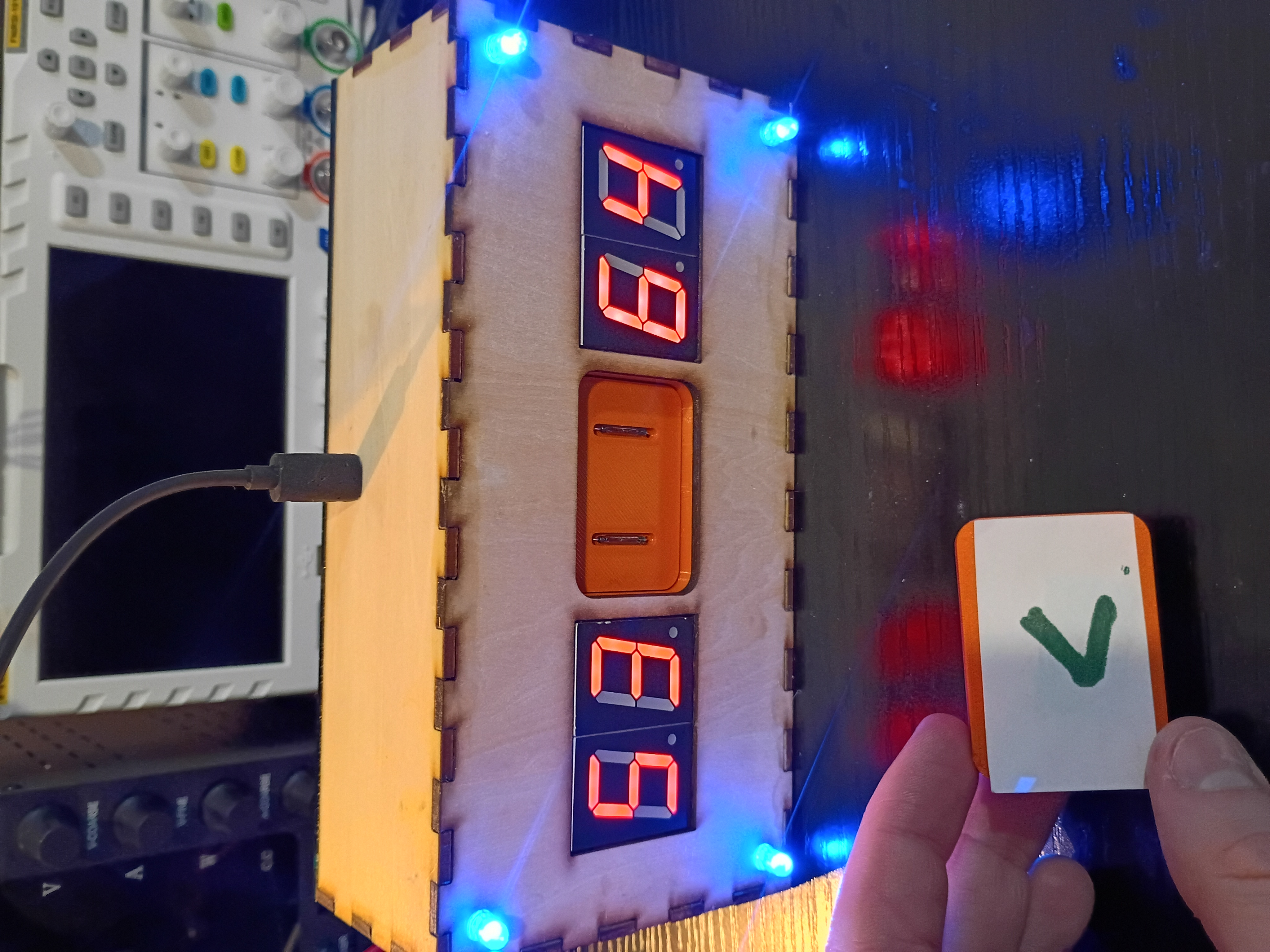
Toyed around with the code for a while, but there is something amiss with the buzzer control timer and the rest of the control logic, so I implemented a buzzer-less version. Had to improve the solder connections, but everything fits in the box pretty well. Needs to be cleaned up slightly. See video of it in action. 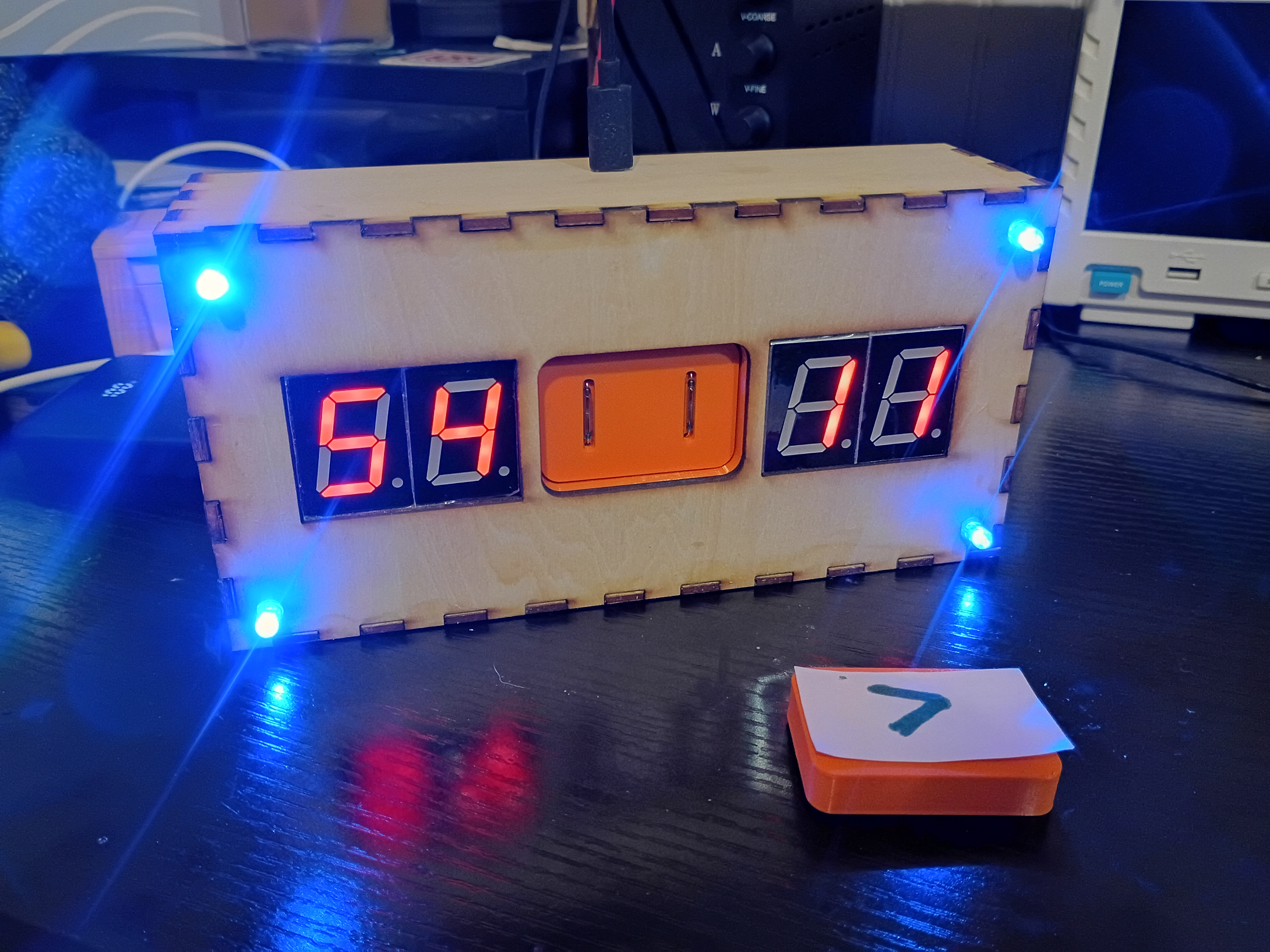
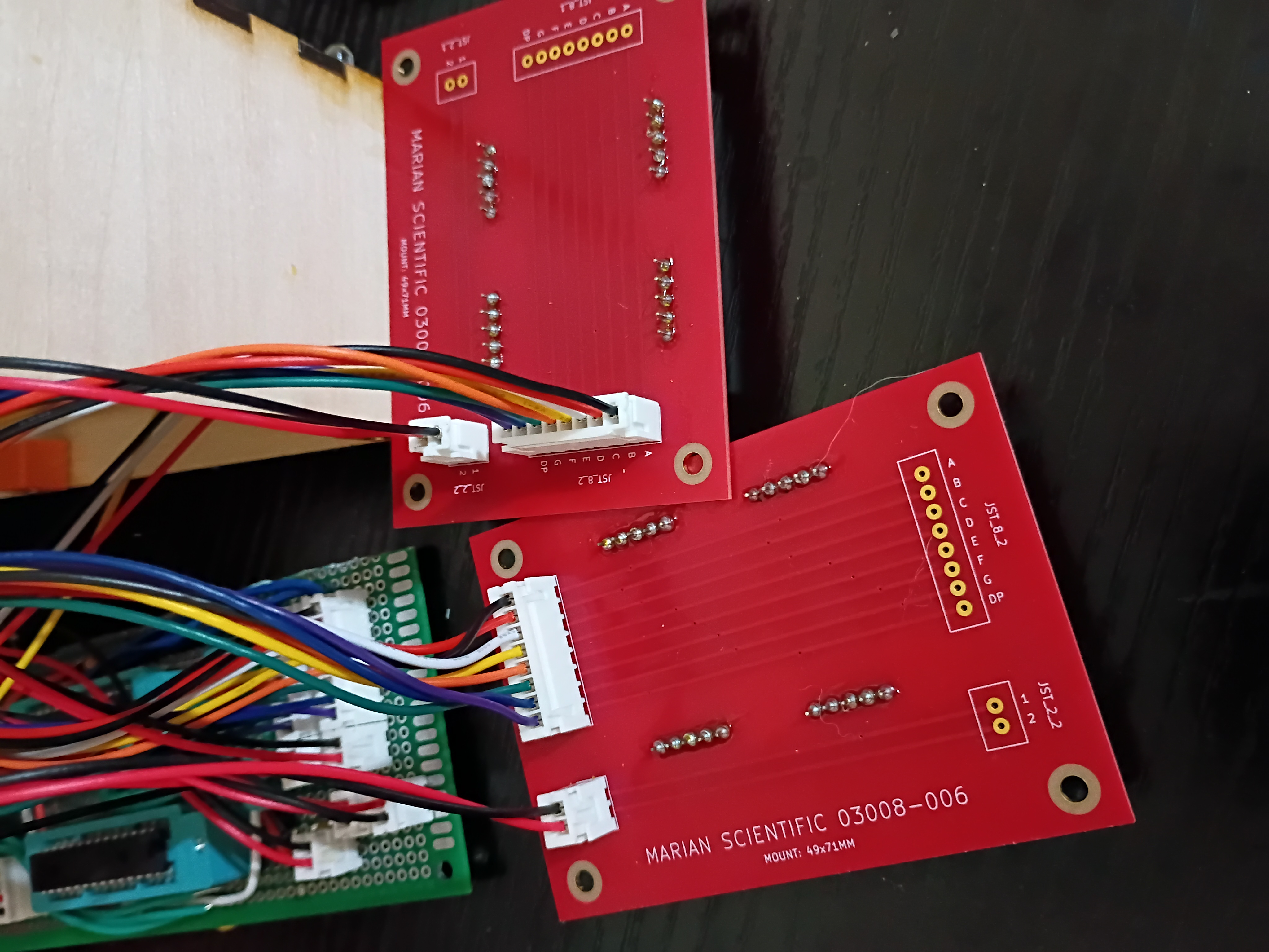
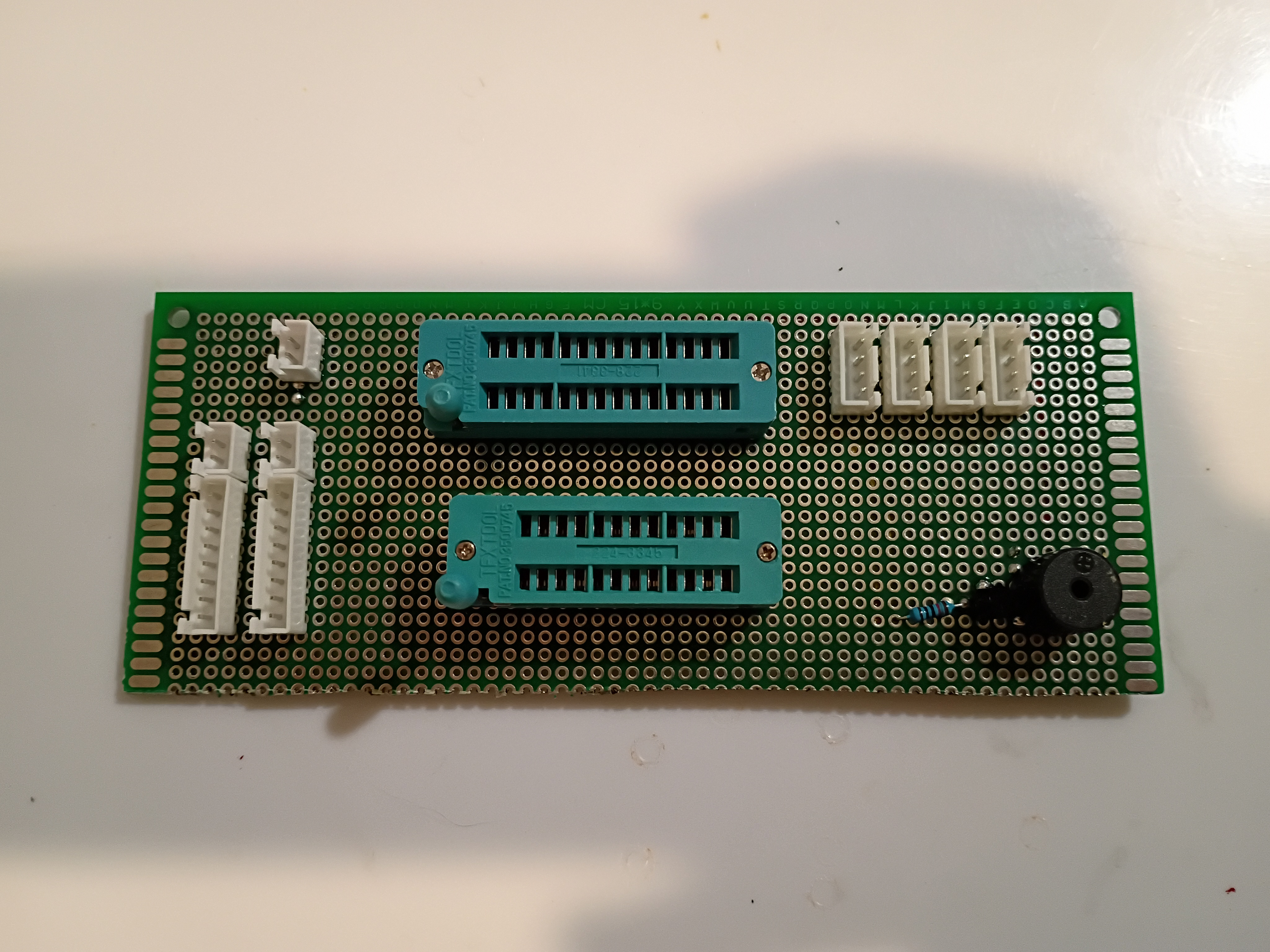
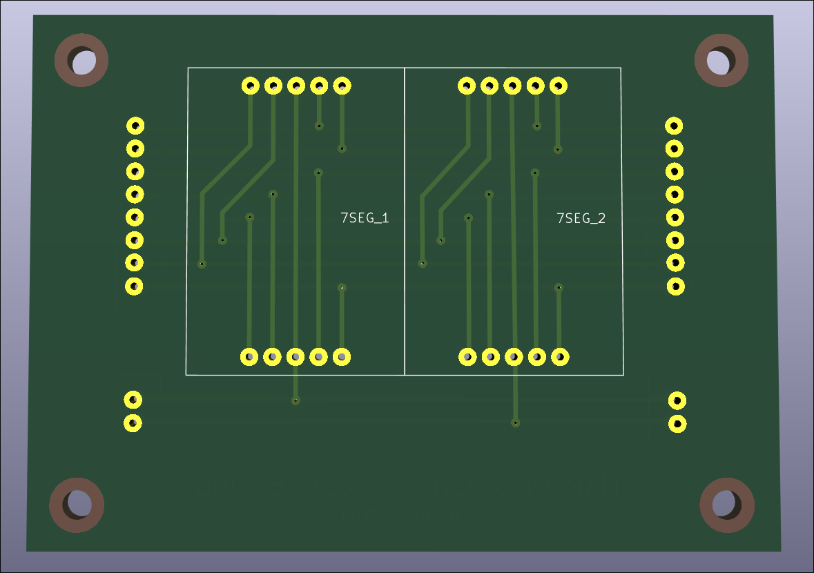
After 2.5 weeks, received 03008-006 PCBs from DKRed. Board quality very good, no mistakes were made on my end or theirs. Silkscreen font kind of squiggly in places. Overall experience was positive, though very slow. They sent 2 extra boards (6 instead of 4). Should probably make the thru holes slightly larger next time. Soldered 7-segments and JST connectors to the PCB and tested some sample code to display digits. There is some software/hardware glitch that is interfering with the buzzer and LEDs. Also, had to hand-crimp the individual JST metal pins to each wire using needle-nose pliers, as the junky JST crimpers I purchased are terrible. I also prepared two additional boards to be shipped out to support the 03009 project. 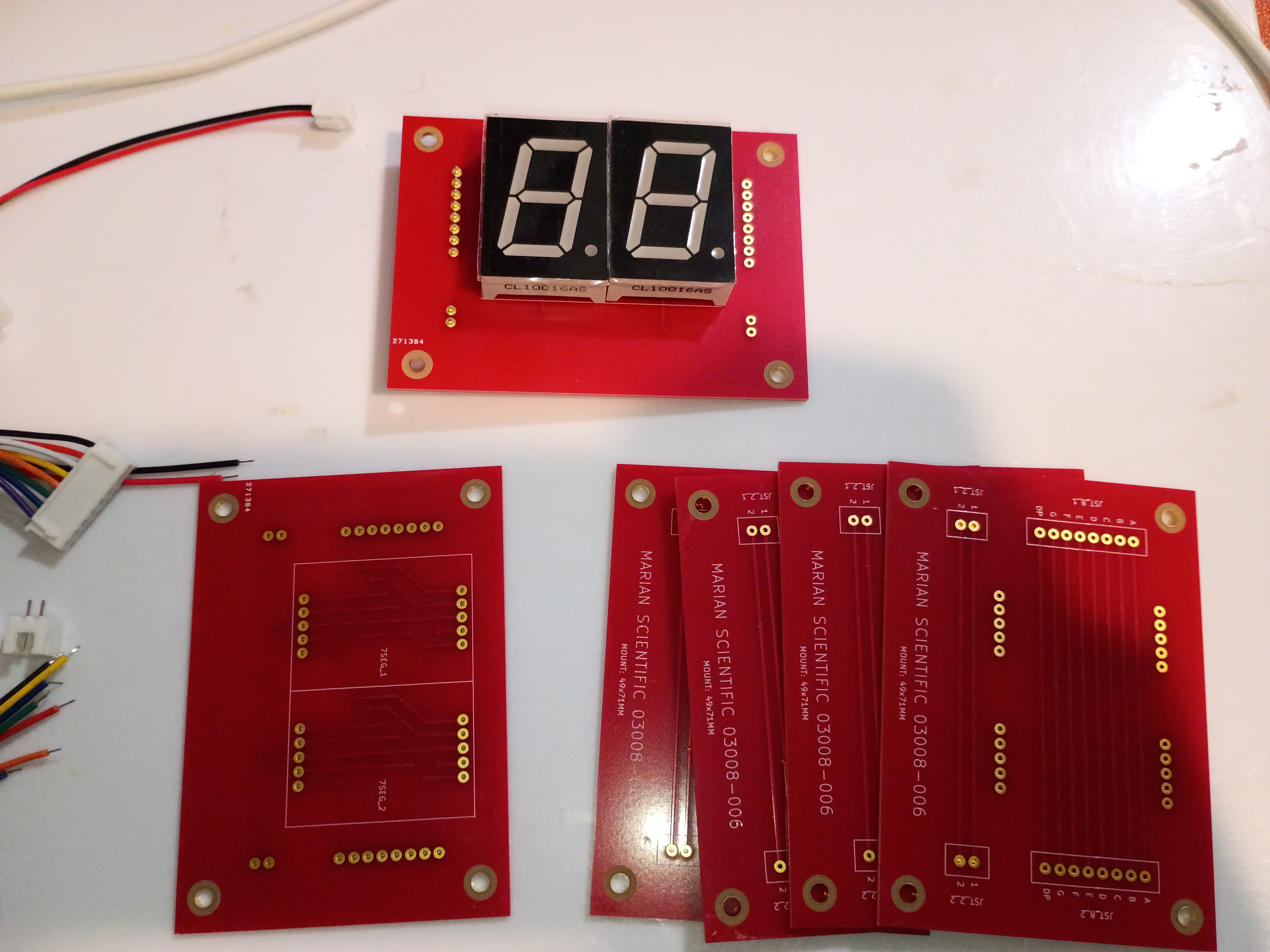
Behold a rasterized version of my 'Alligreater' SVG to be either laser engraved cut or printed/laminated/pasted to the front of the magnet block. 
Compiled the full project code from the minimum viable test cases, but I am unable to test it easily until USPS delivers the 7-segment breakout PCBs, which were supposed to be delivered yesterday.
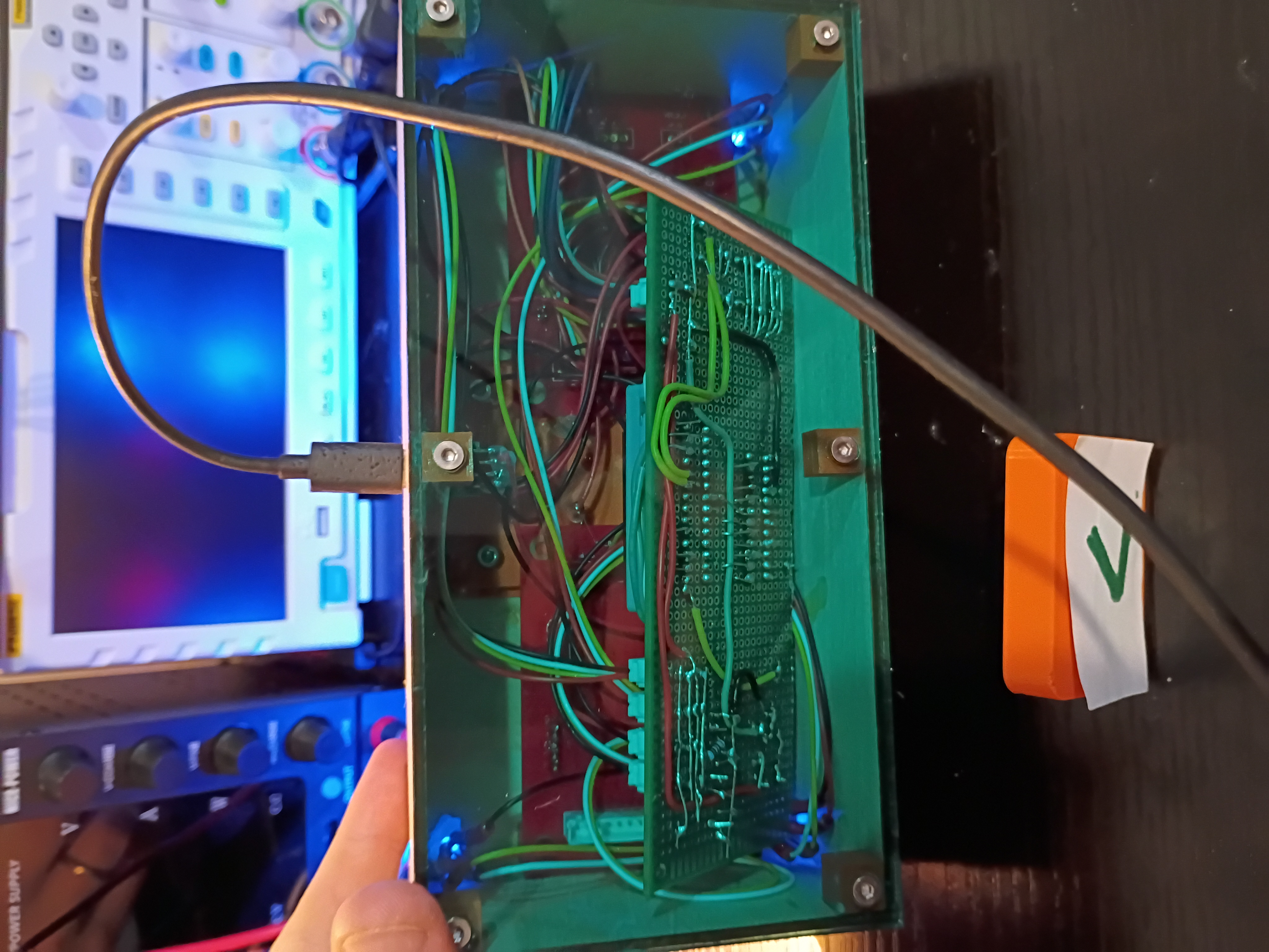
Snipped down main circuitboard to fit snuggly inside the box. Debugged minor soldering issue with one of the RGB LEDs. Wrote this code to control the lights in unison with the buzzer depending on the reed switch status. See video example. 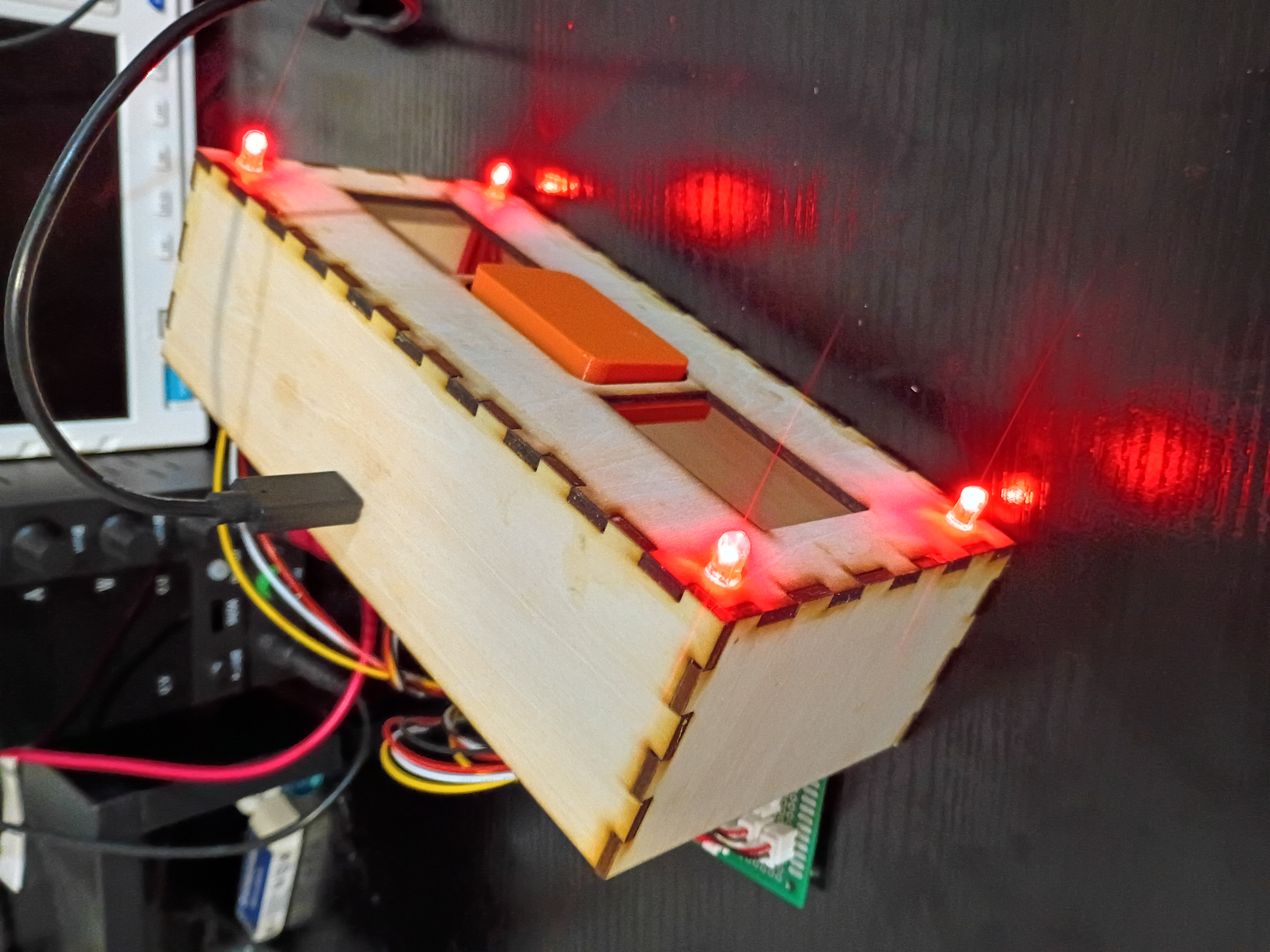
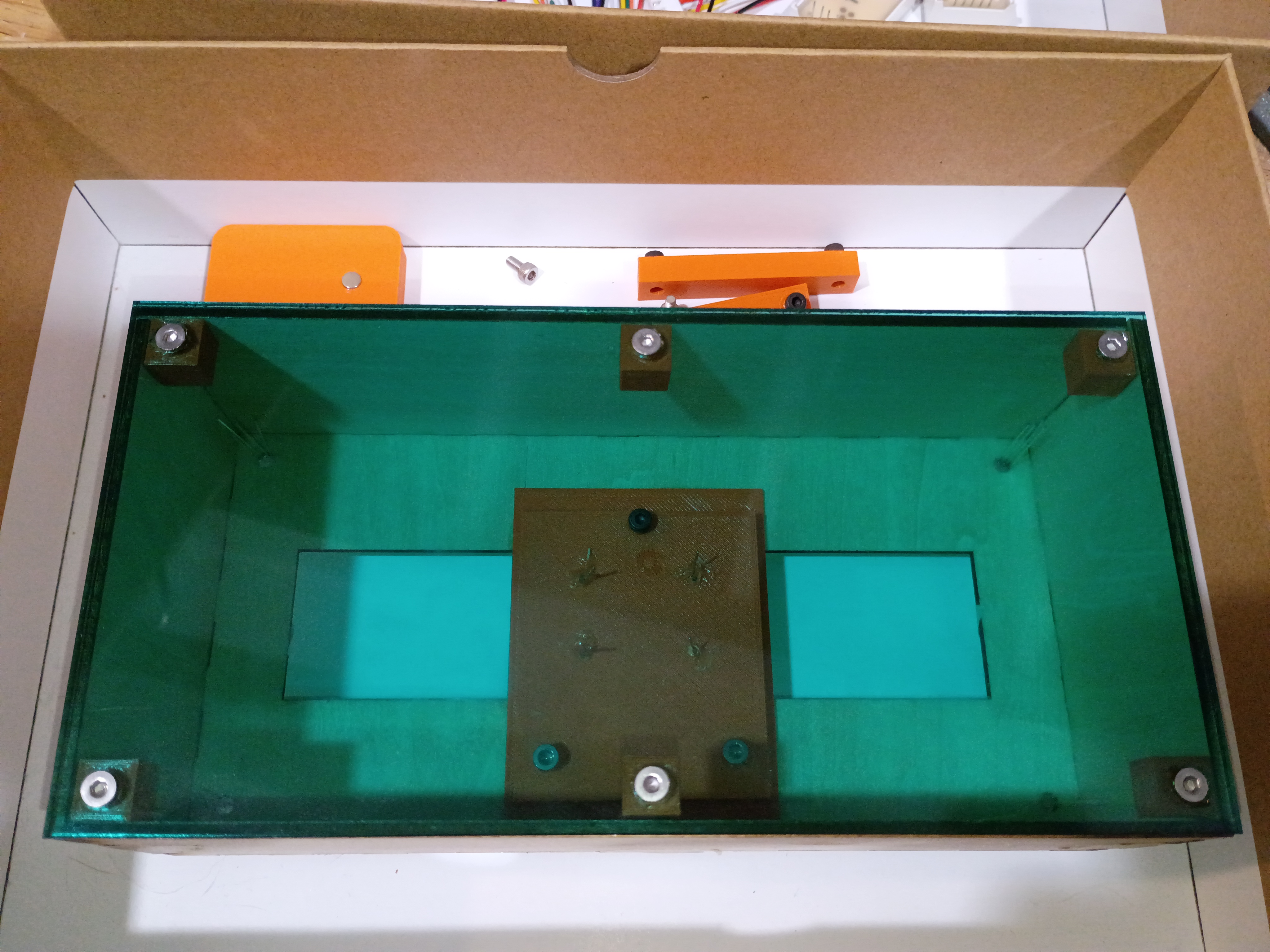
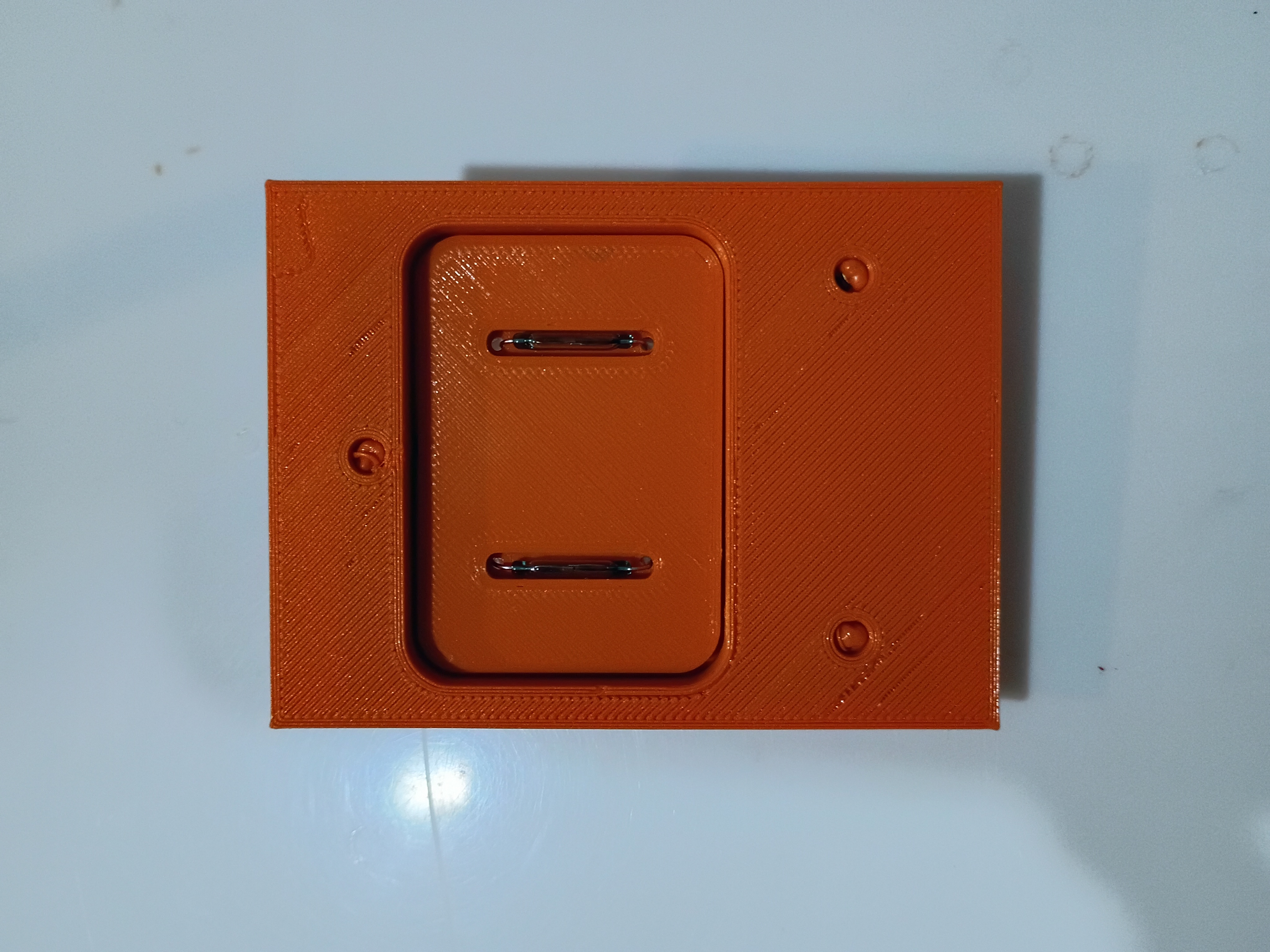
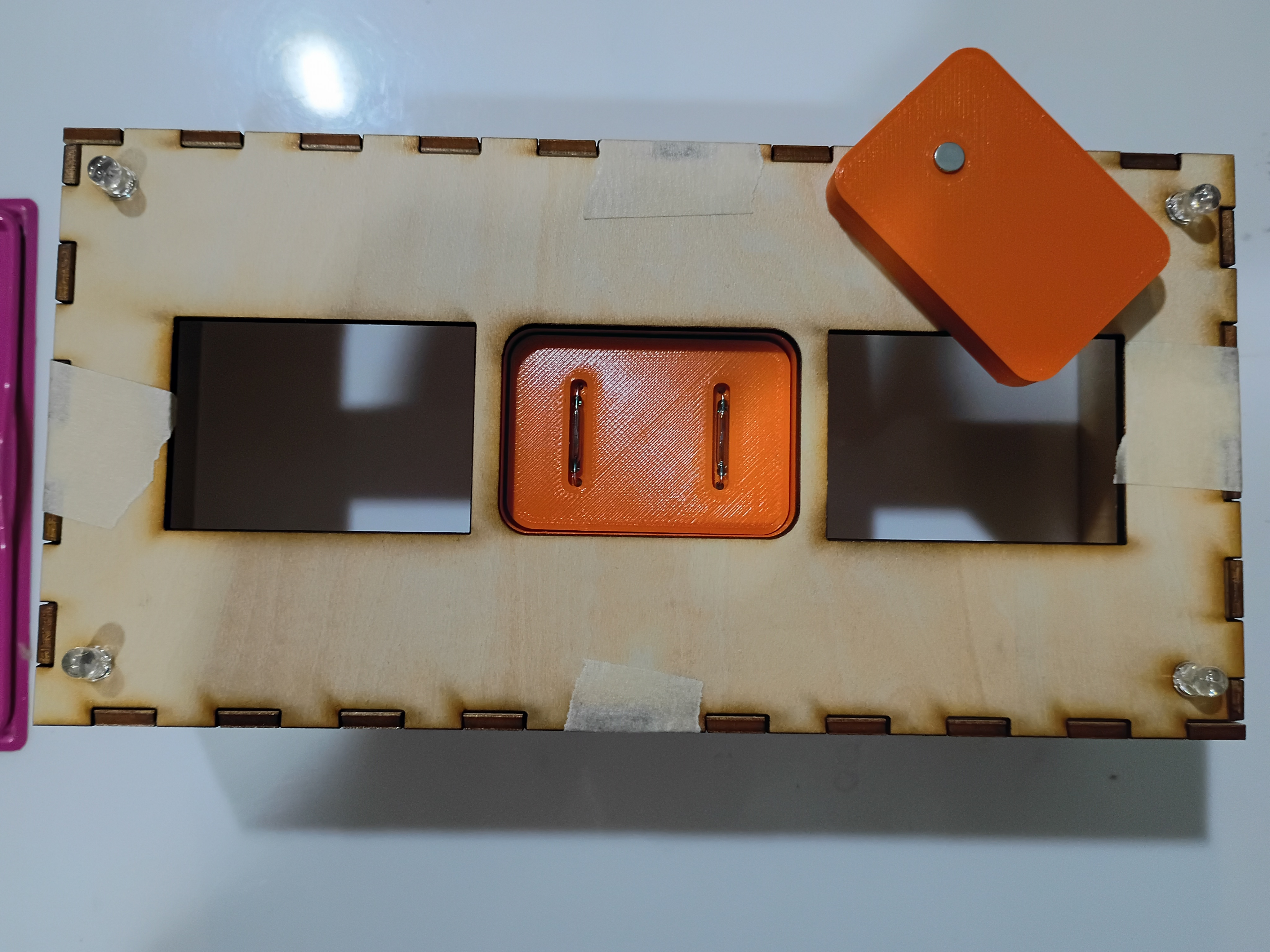
Reprinted magnet block with 2 holes to accept 2 magnets which must be oriented with opposite polarity facing out for best detection by the reed switches. See example. Also glued mounting blocks for the bottom acrylic plate. 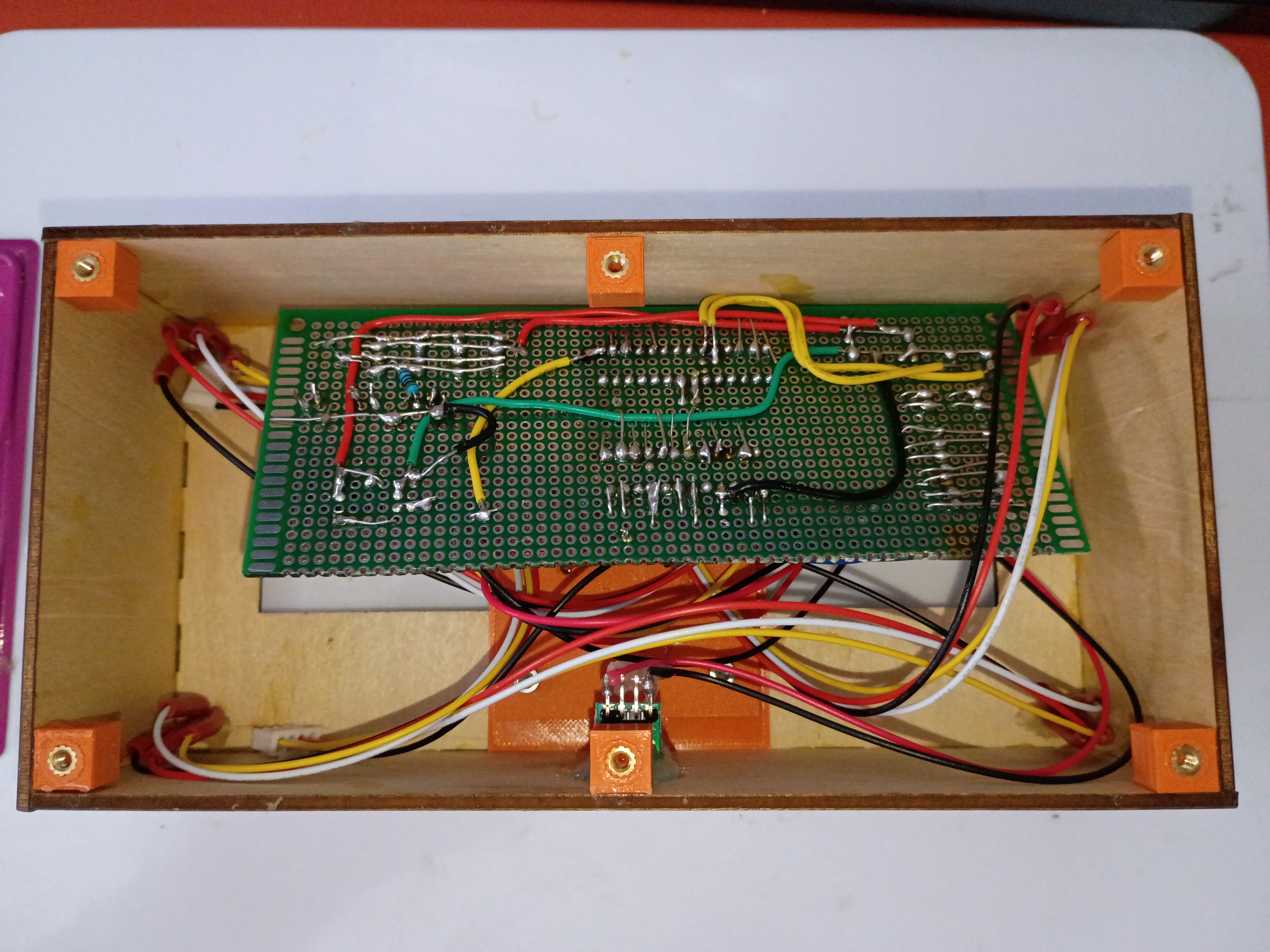
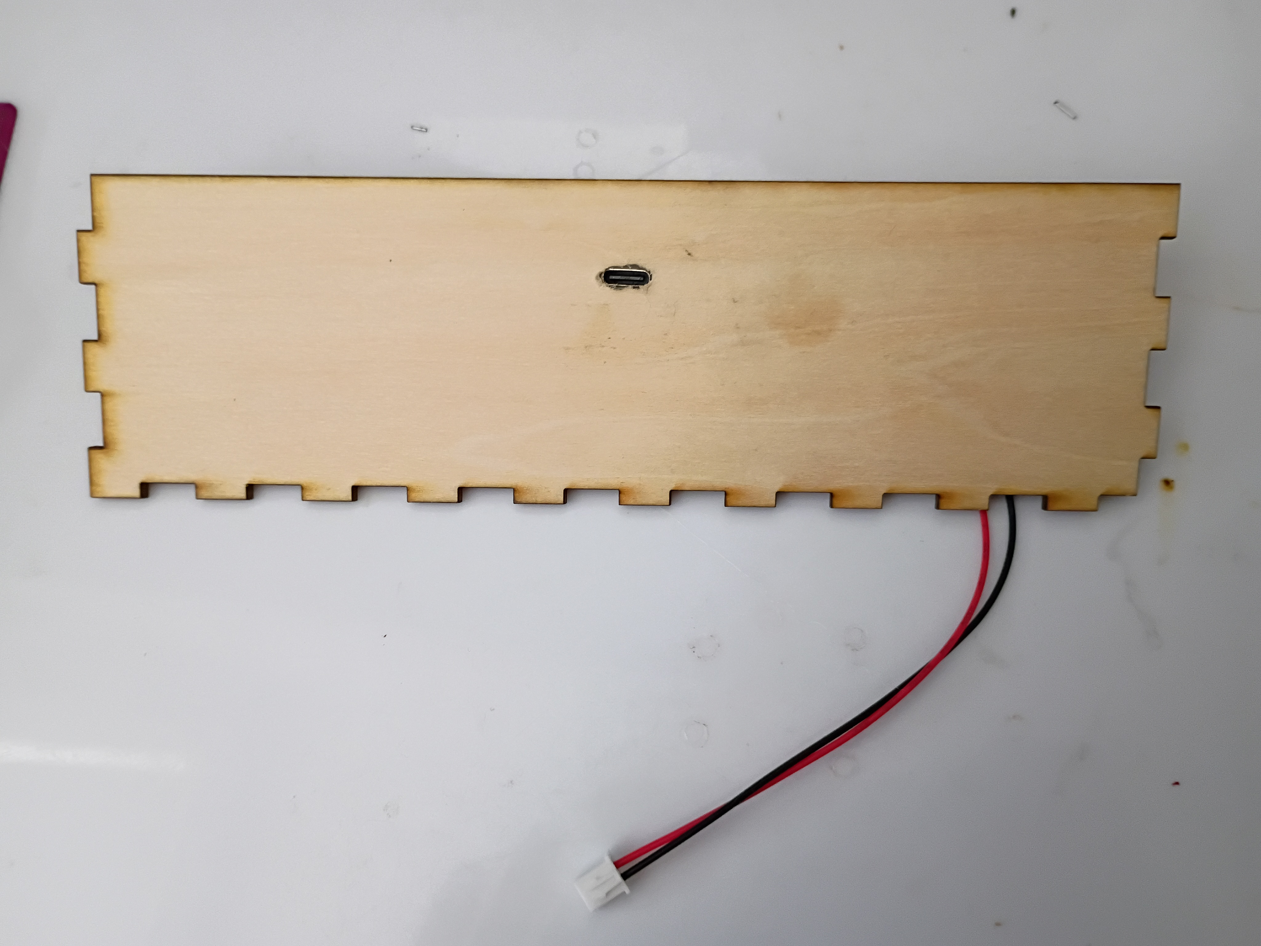
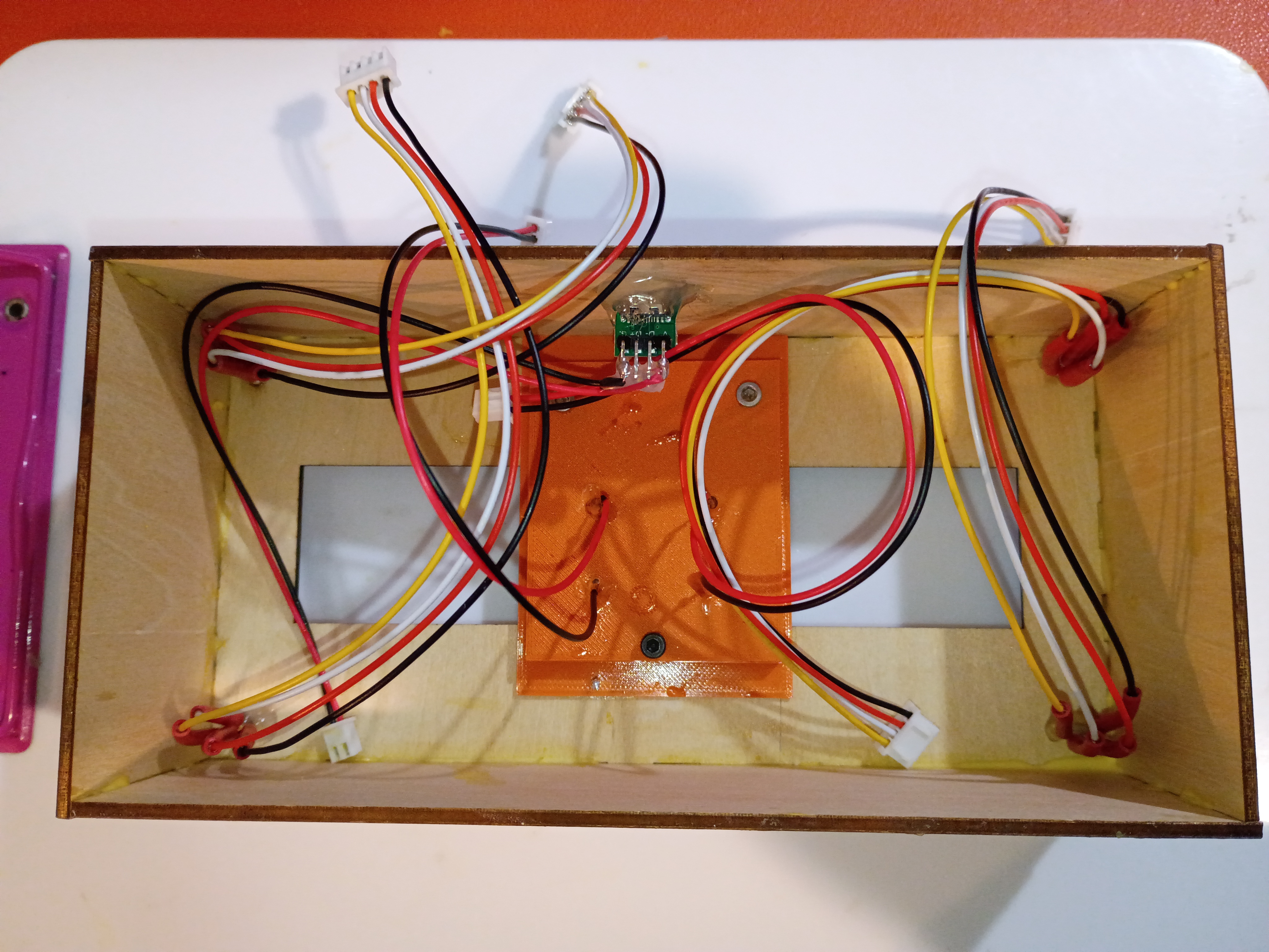
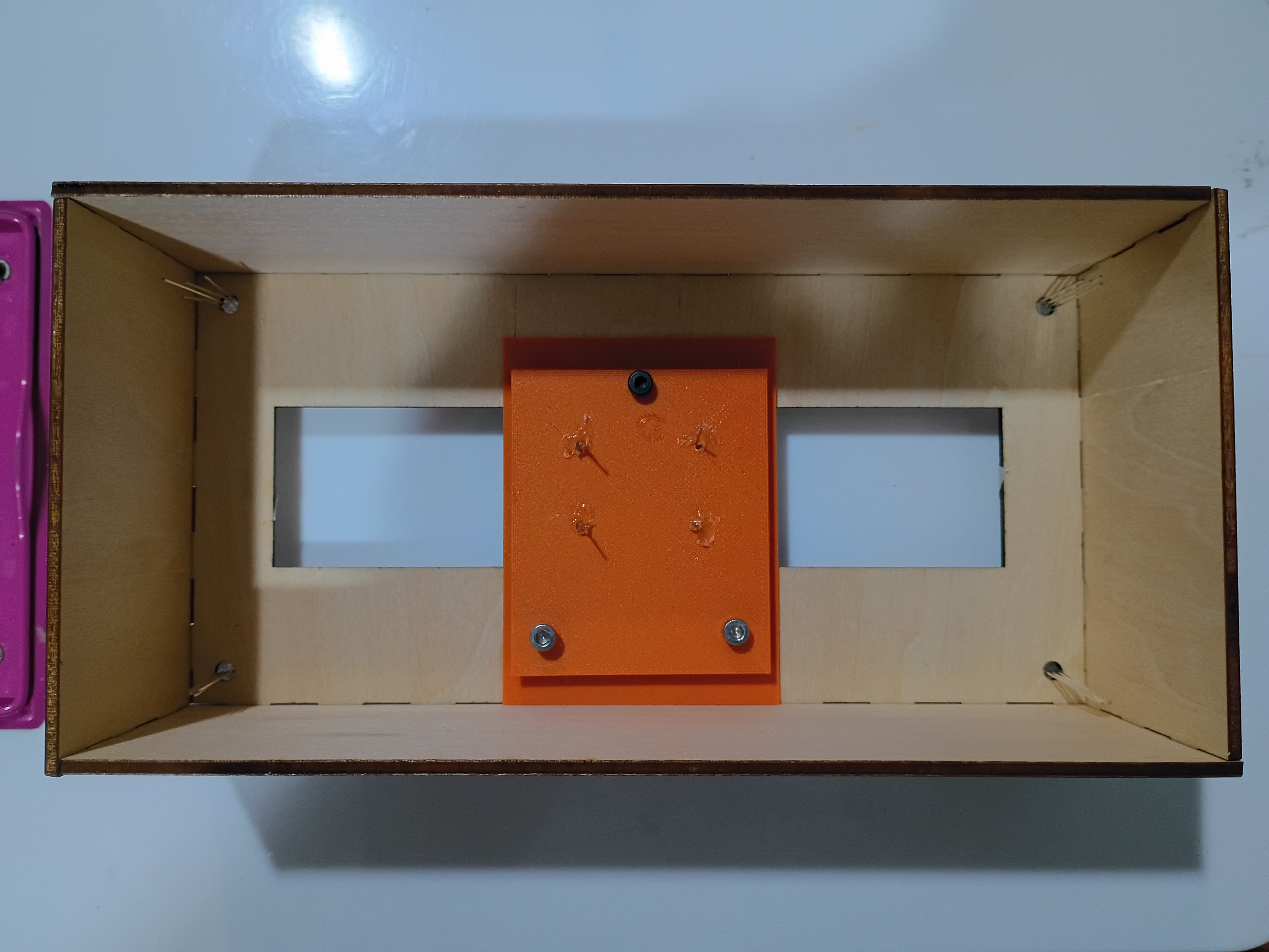
Drilled slot in box and mounted USB-C connector. Mounted, soldered, and heat-shrunk leads to all indicator LEDs and reed switches. Soldered additional JST sockets for the reed switches onto the main circuitboard. Glued box together. Tested magnetic field detection with this C code. 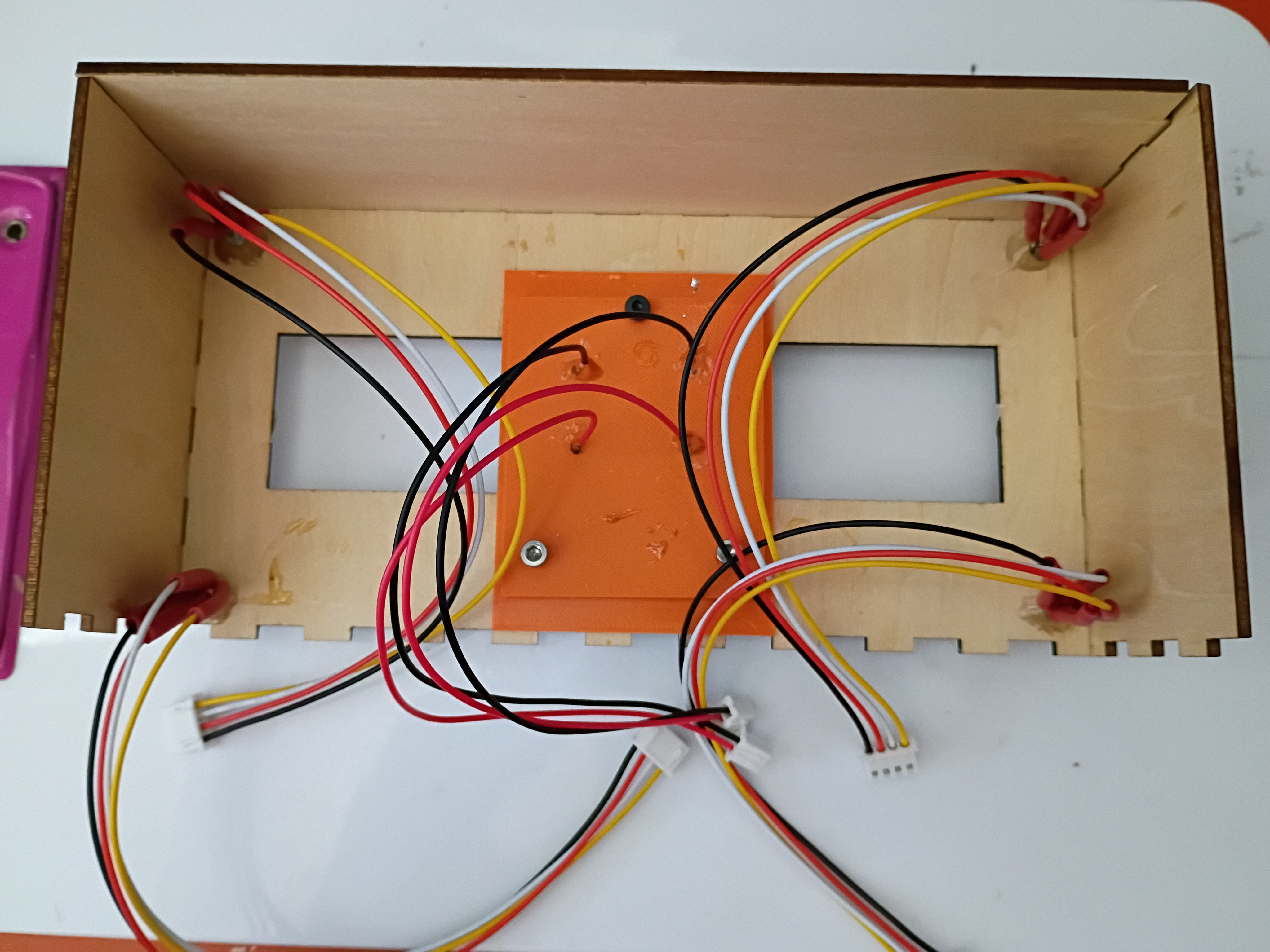
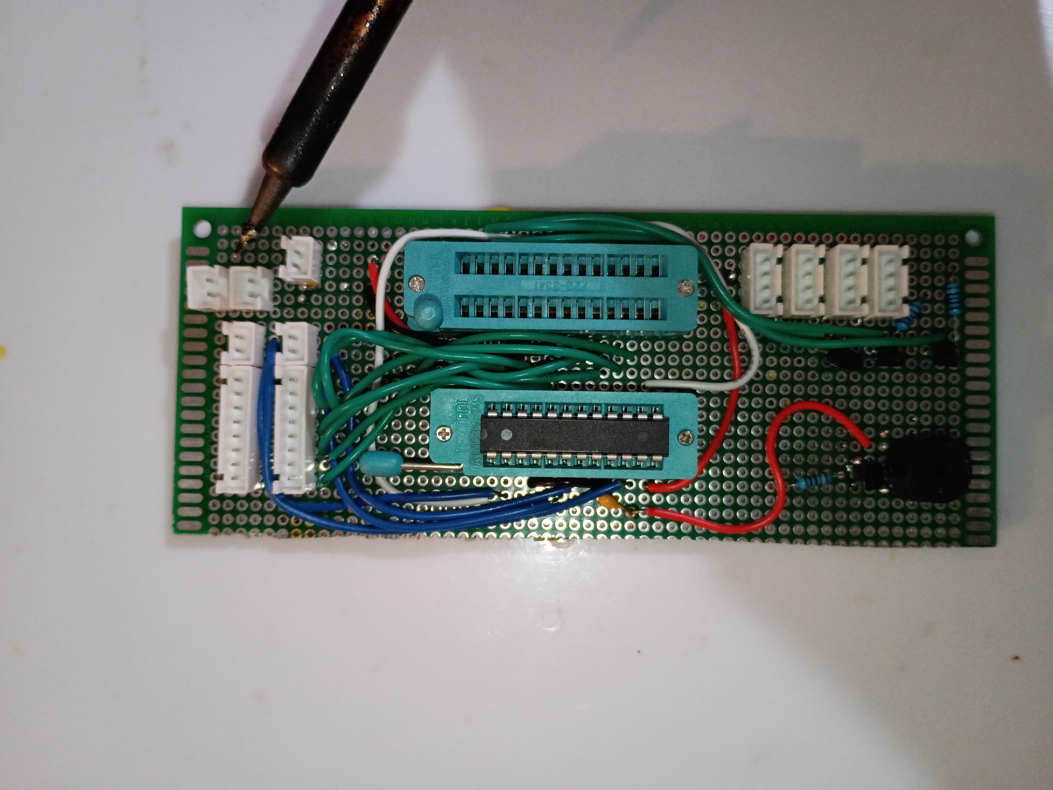
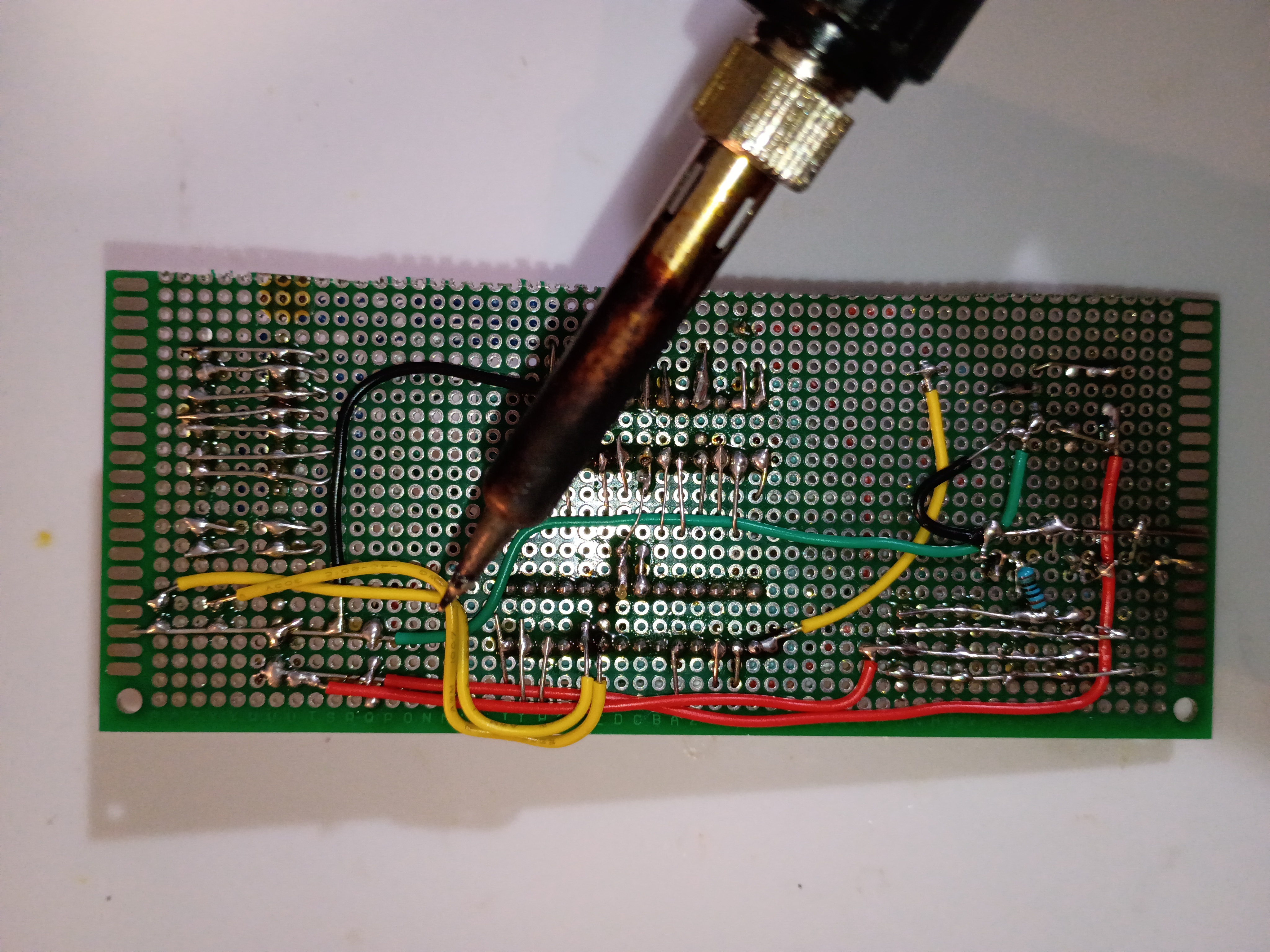
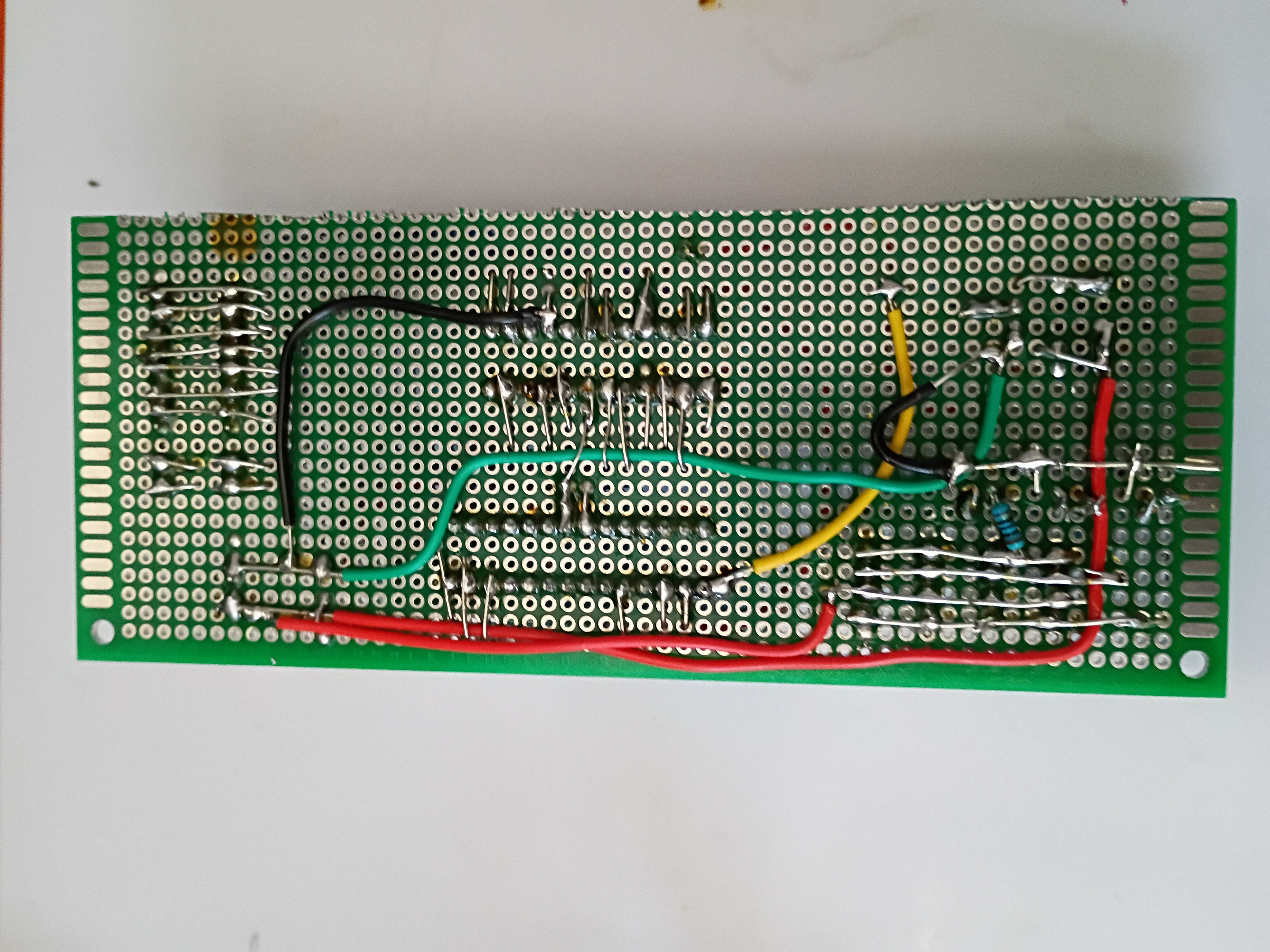
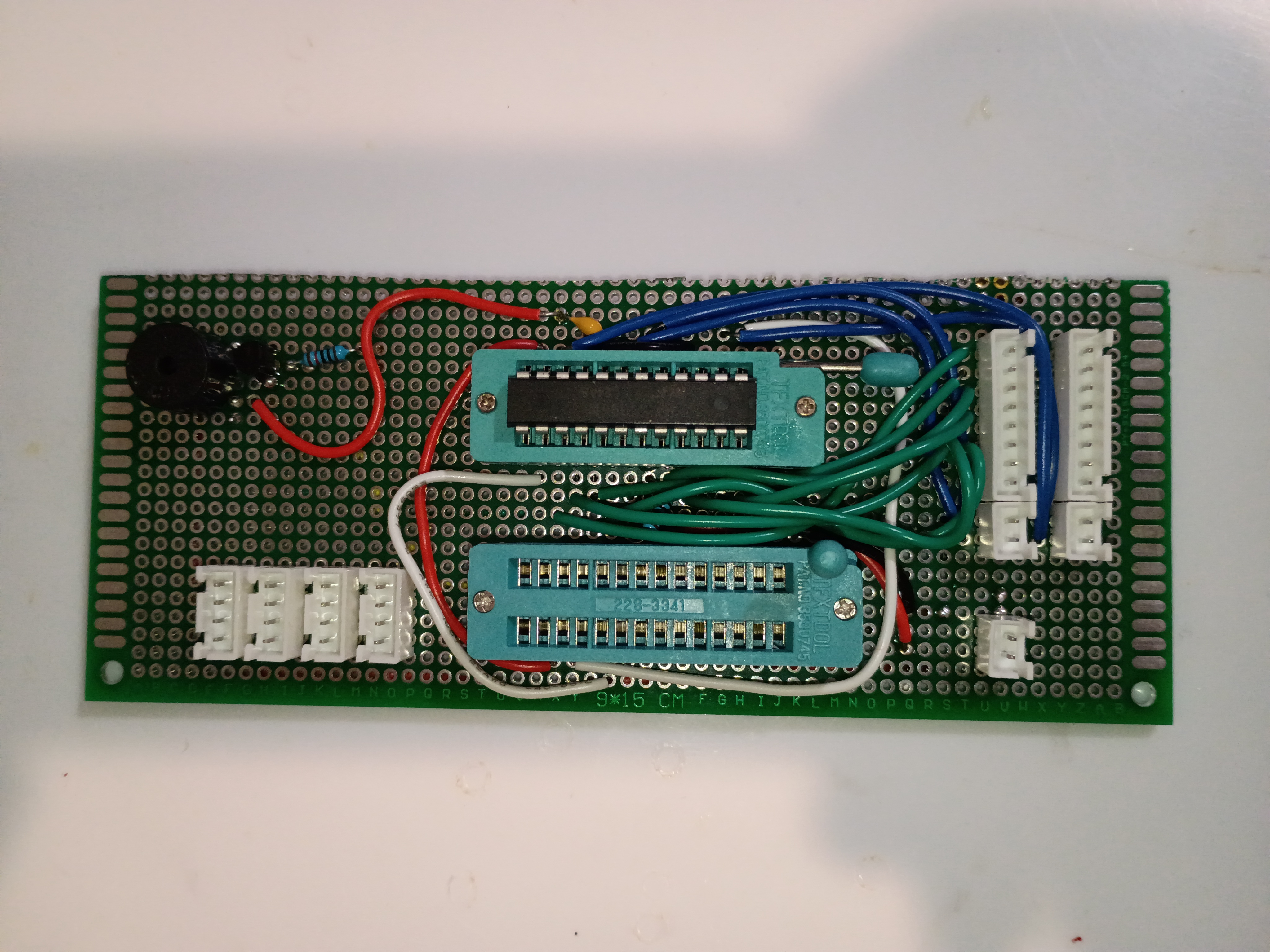
Finished soldering components onto main perfboard. 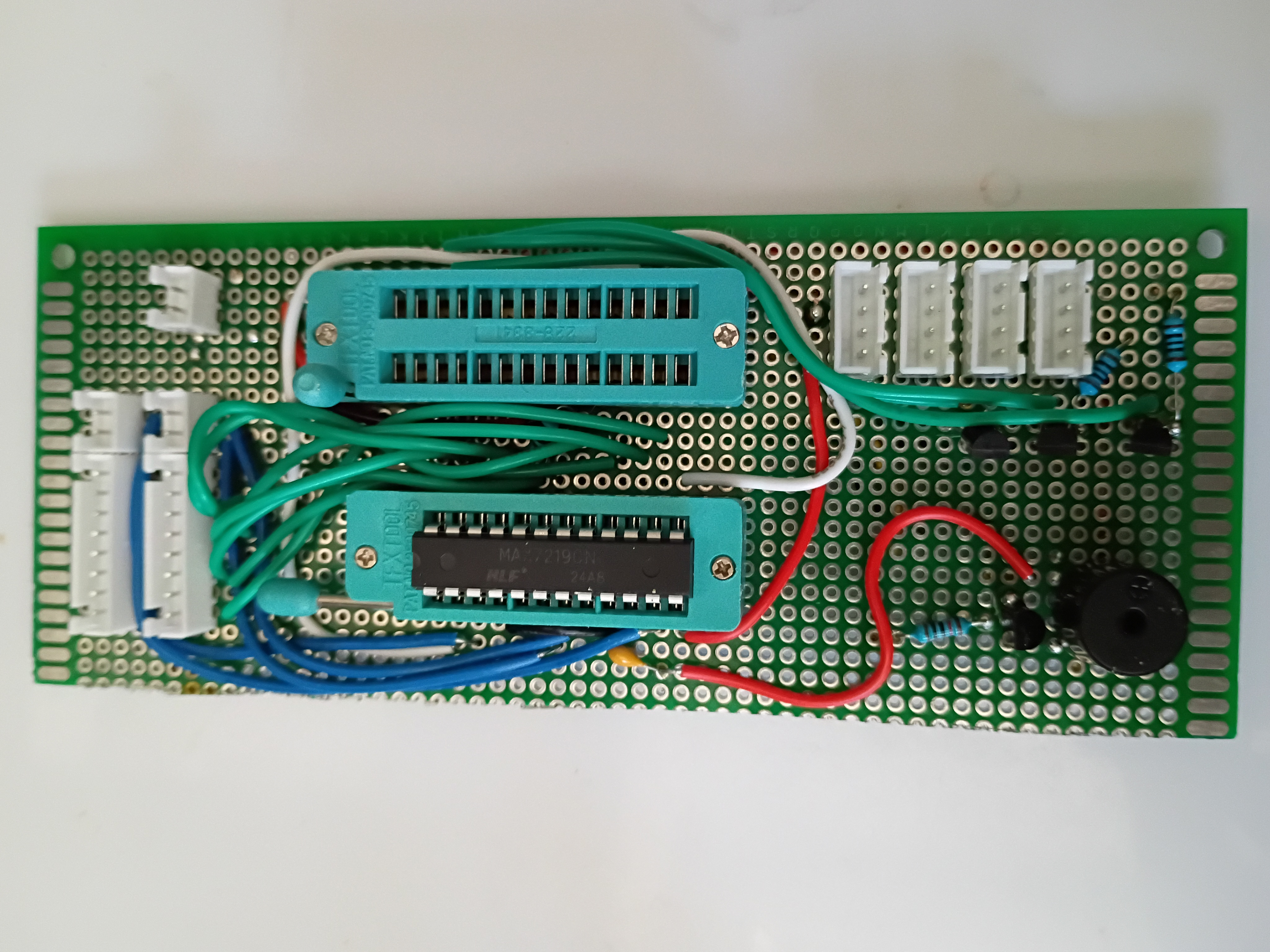
Circuit and code to blink multiple RGB LEDs in unison using 2N7000 mosfets since they draw slightly too much current to be driven by GPIO directly. 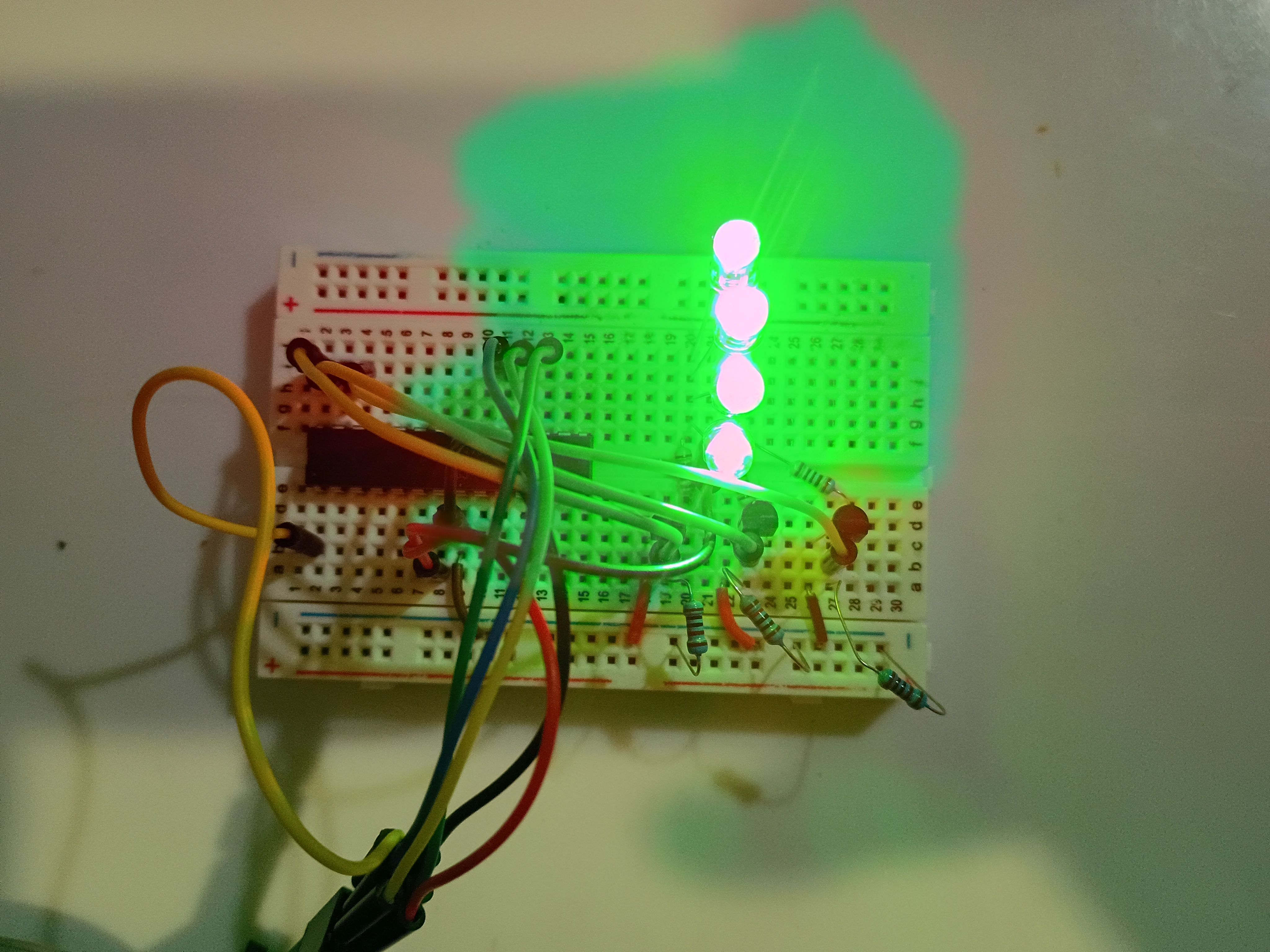
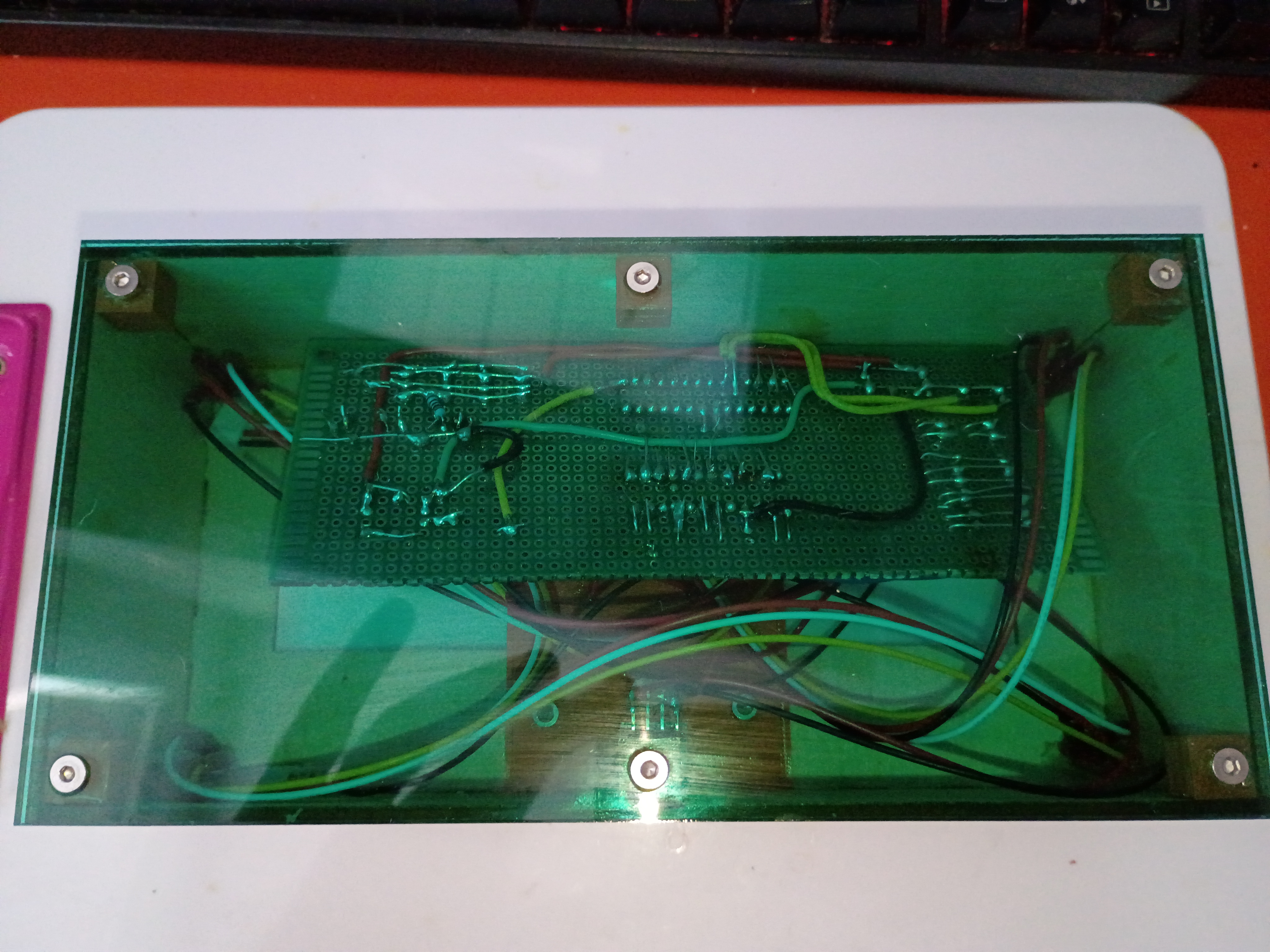
Laser cut 3mm acrylic bottom panel (30% speed, 100% power/current, 45W, only slightly caught fire). Countersunk holes for M3 screws (tendency to shatter, will not do again). Did a dry fit with the rest of the box. Continued to solder more components. 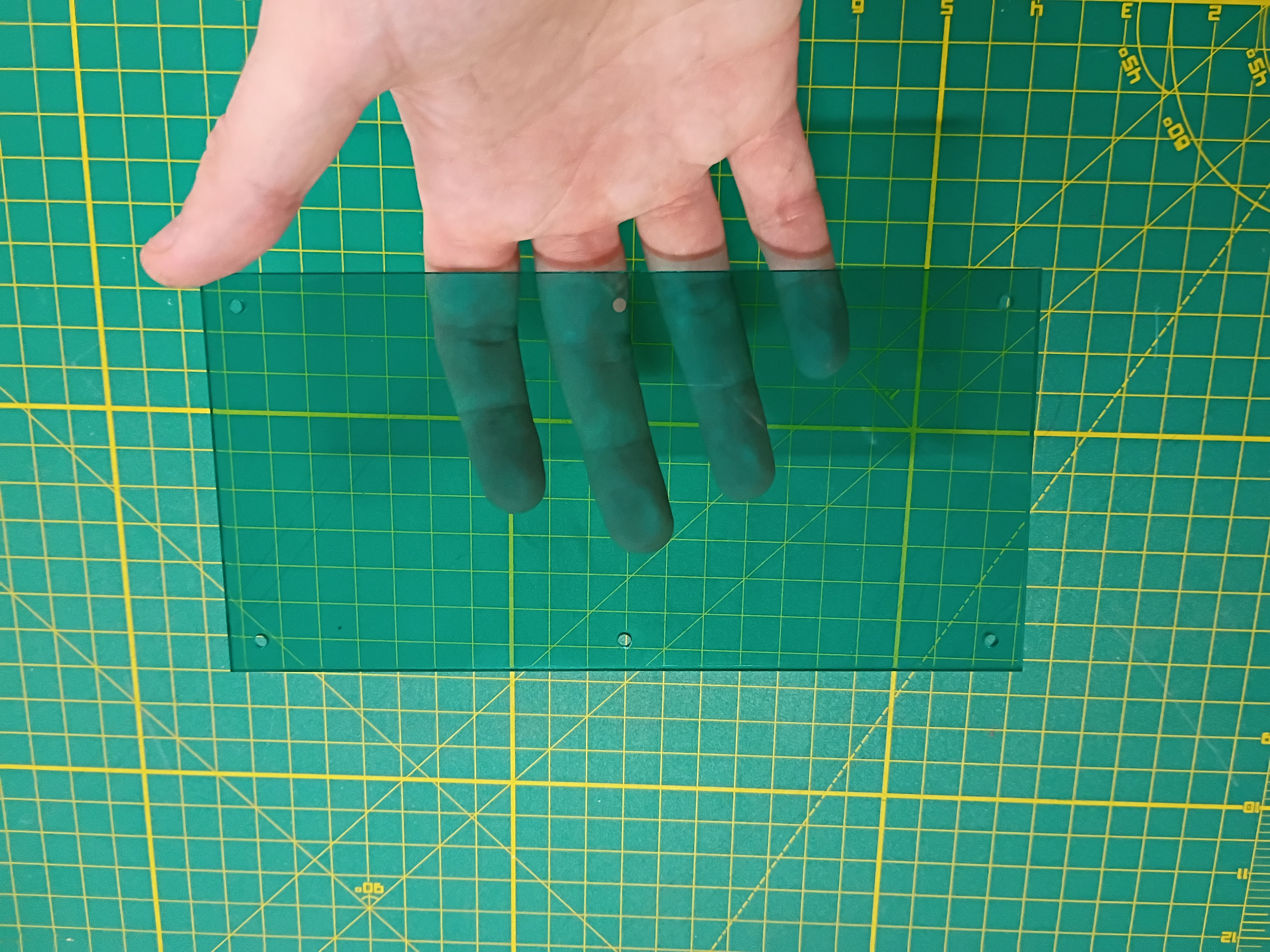
Cut perfboard with hacksaw and soldered several components. 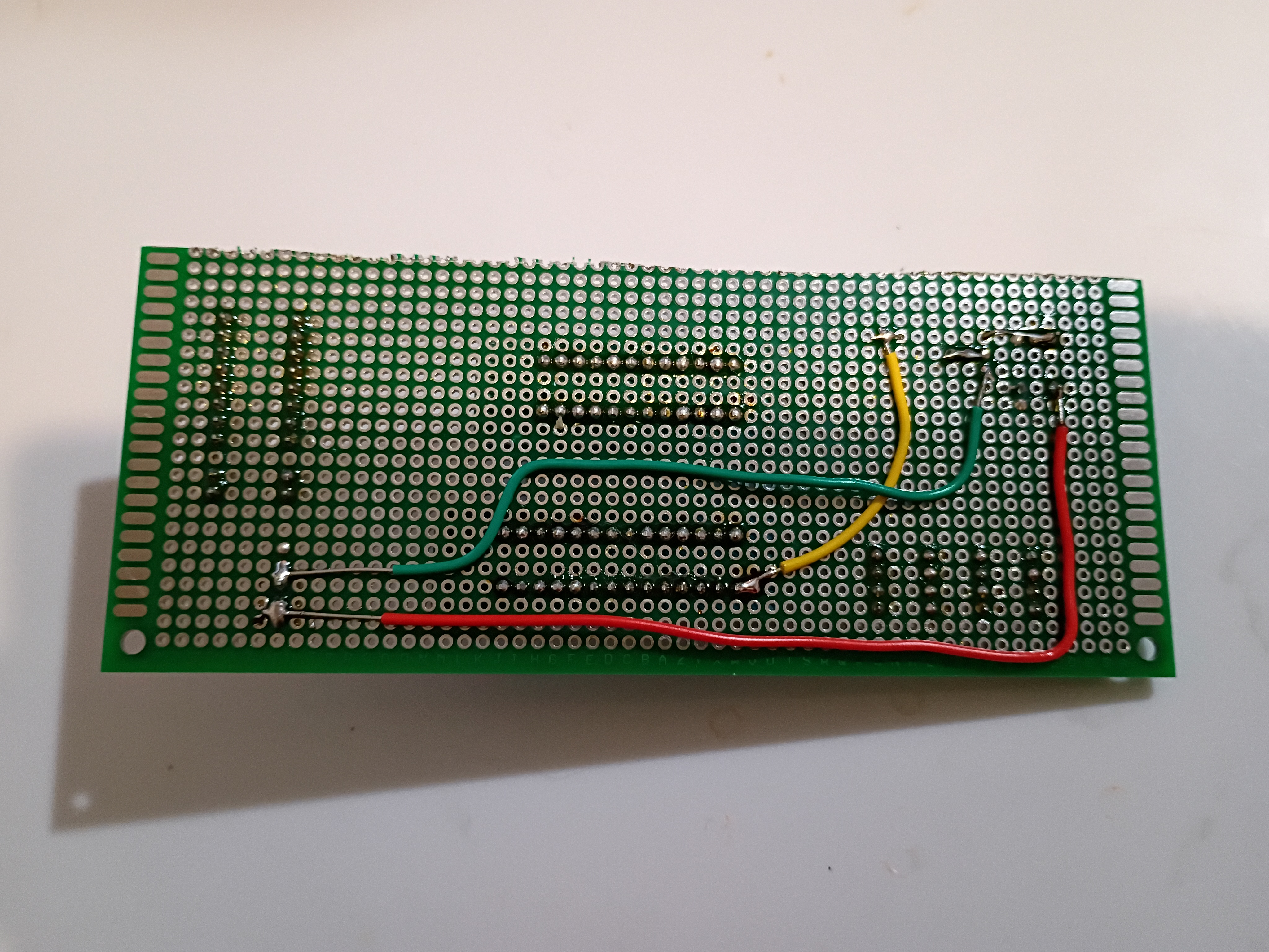
Got buzzer jingles and random integers working on Atmega328P using this C code to scare my cat.
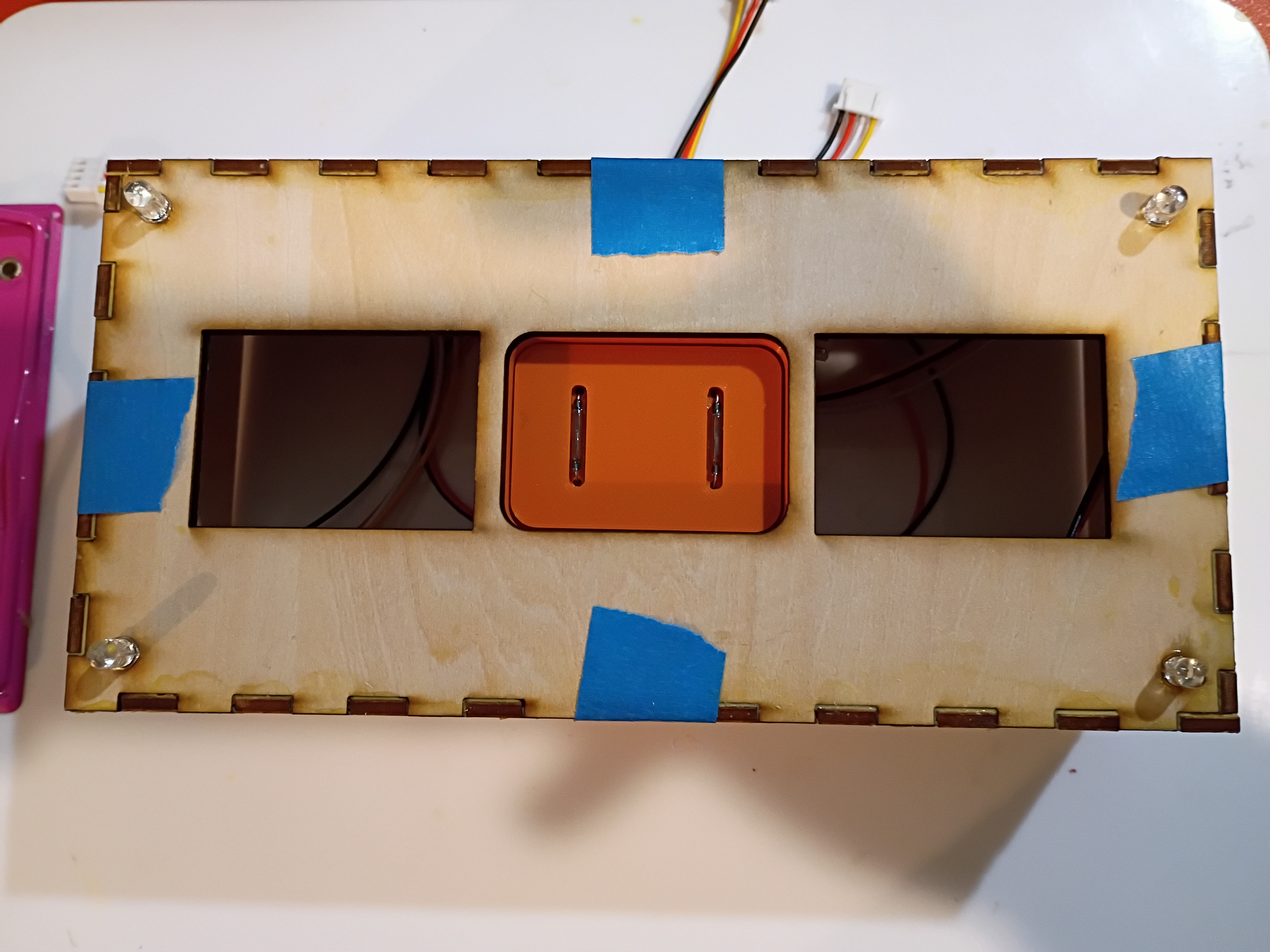
Printed additional mounting components and installed M3x4x5 heat-set inserts. One trick is to set them 75% in and then flip the part over and press it into the table; that gives the best surface finish. Installed reed switches and central chassis onto underside of box surface. Installed small magnet into plastic block for testing purposes only. 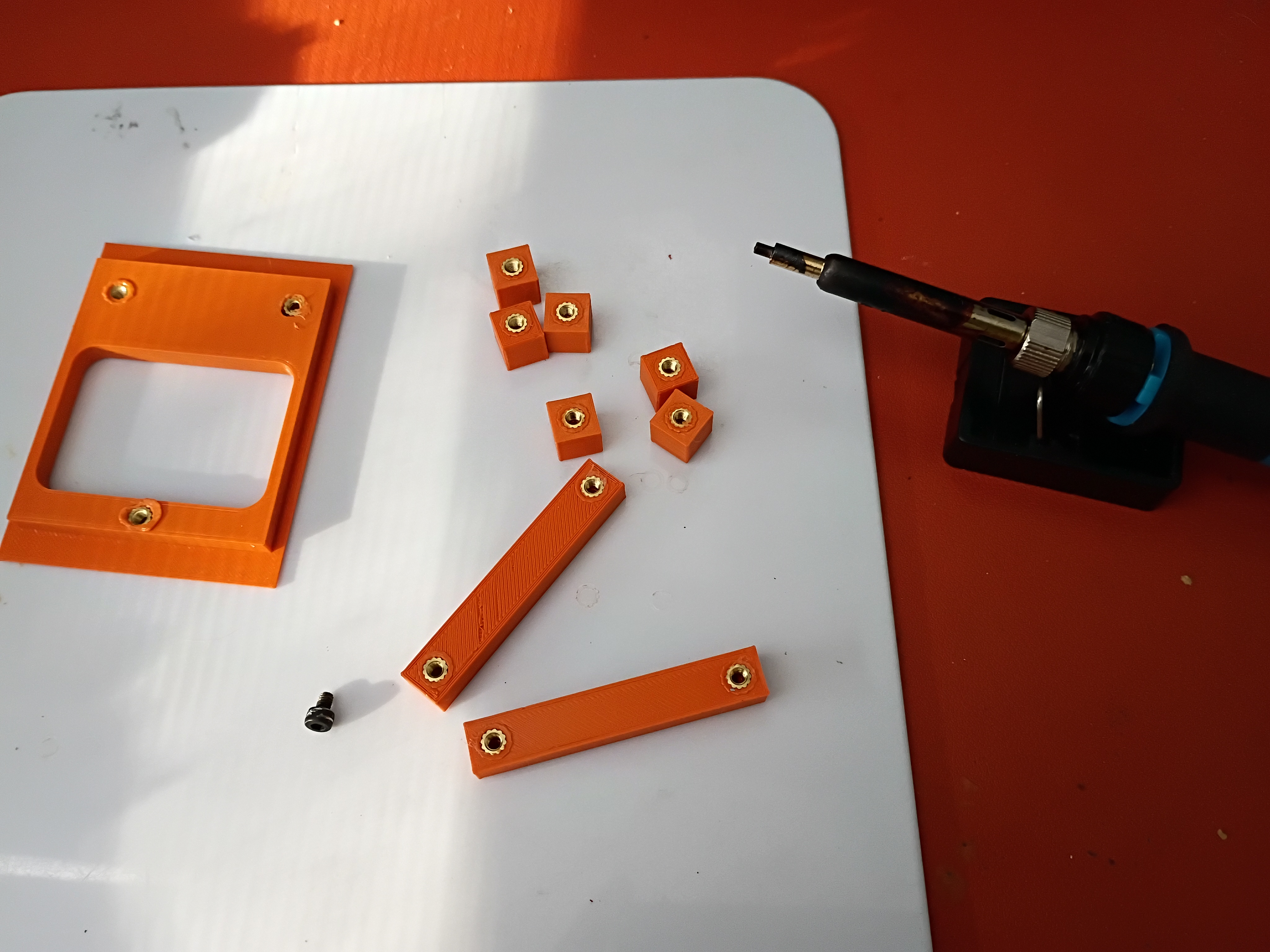
Continued to model assembly and began printing mounting components. 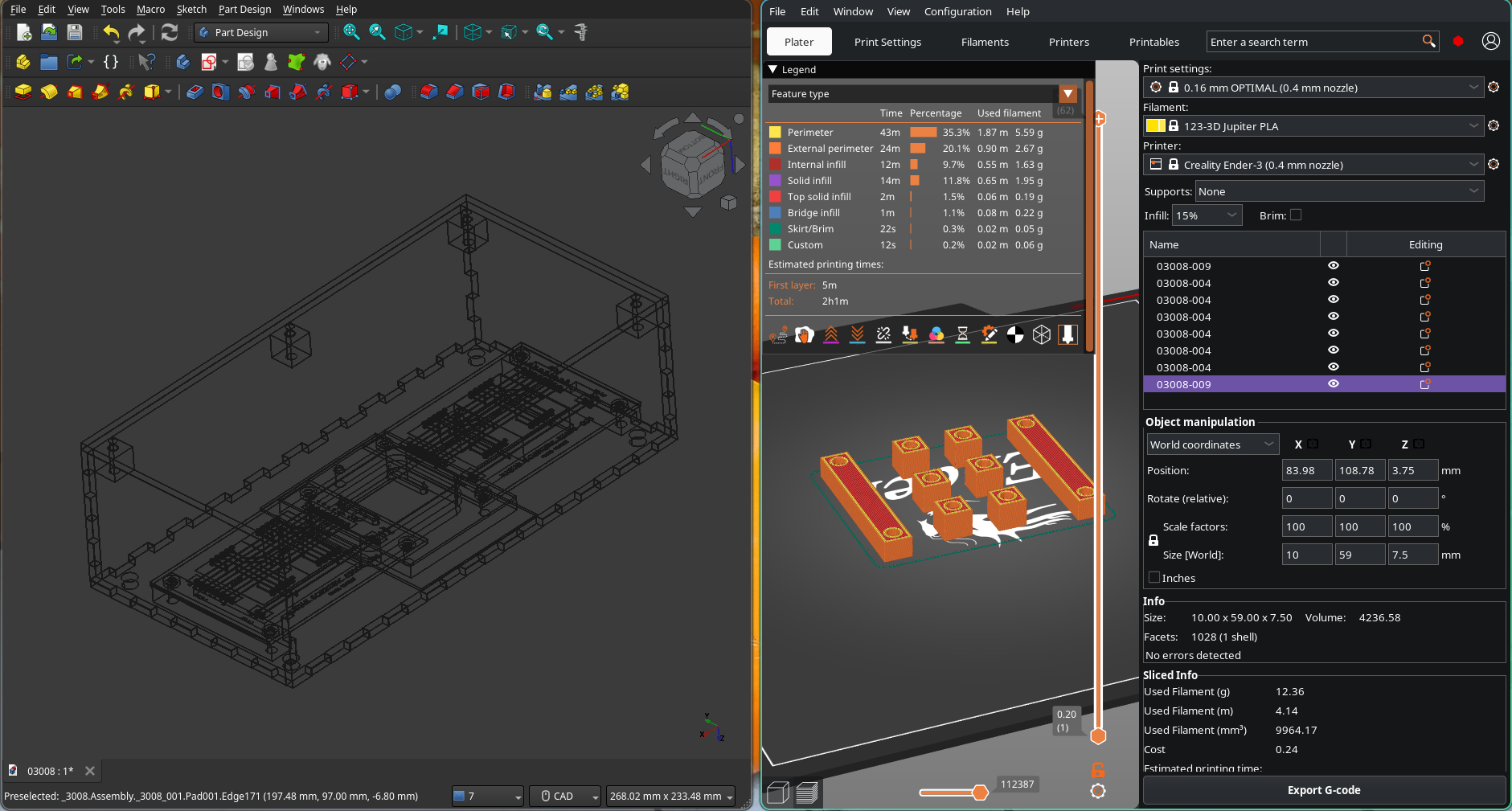
Mocked up removable reed switch holder and partial PCB support assembly. 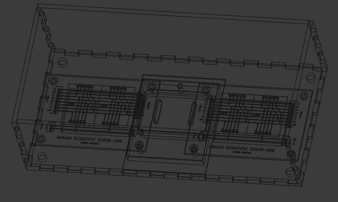
Designed (KiCad) and ordered PCBs (DKRed) to break out sets of 2x 7-segment displays to JST connectors. Cost per board was 11 dollars shipped, made in USA, to arrive in 10 days. Price seems mostly to do with board size. Decided not to expedite the shipping. 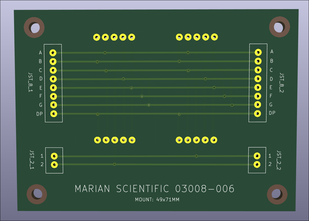
I conducted a preliminary fitment test of most of the electronic components in the box. I determined that getting small custom PCBs produced will drastically simplify the wiring and keep the box contents neat and robust. 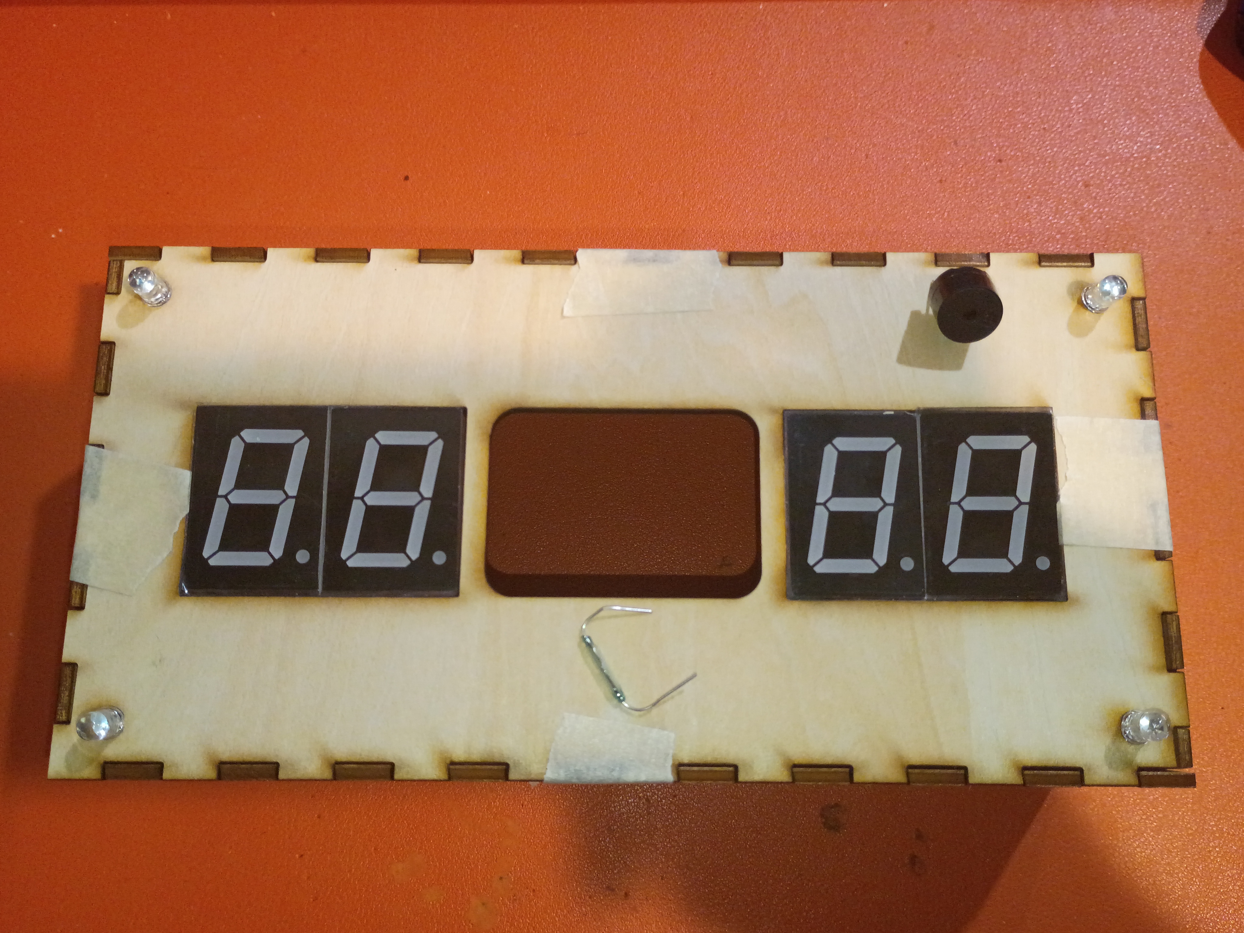
Most of draft box laser cut from 1/8-inch plywood with 3x10mm rectangular jagged edges. 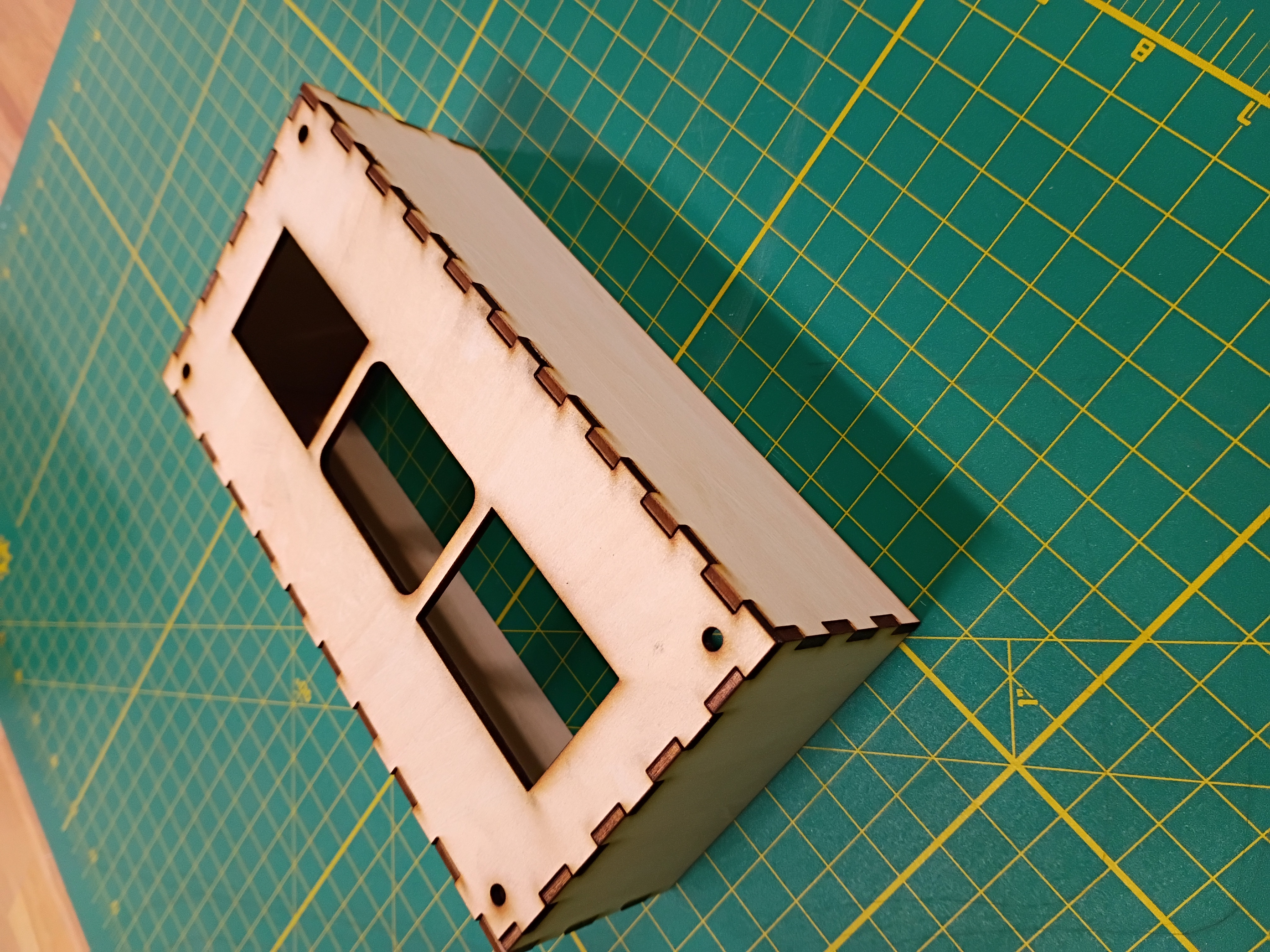
I wrapped up the 3D and laser cut definition for the box sides. 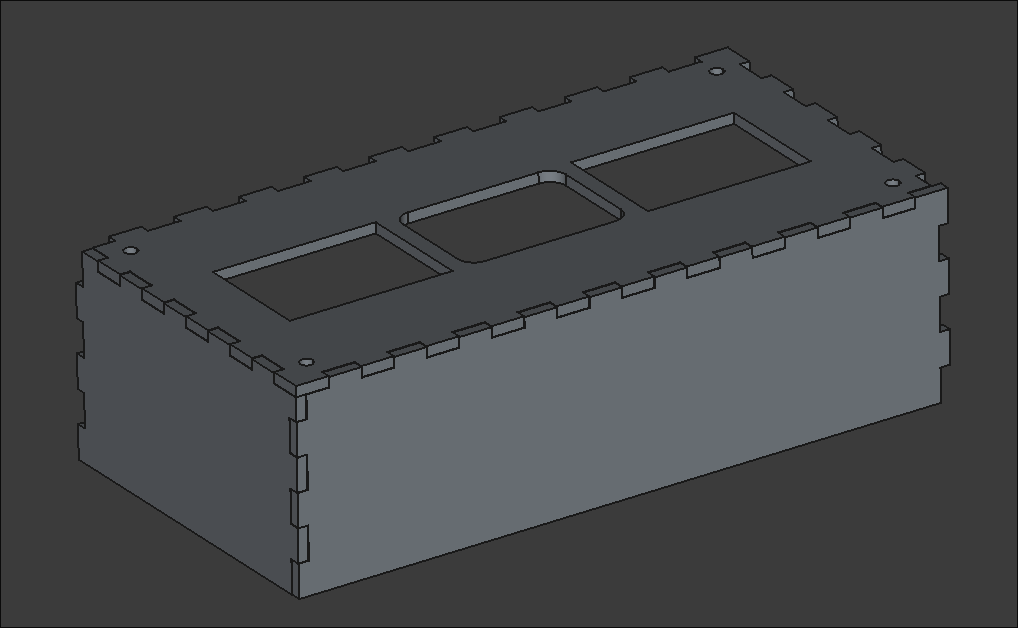
I mocked up a preliminary faceplate SVG to be laser cut. It has holes for the 7-segments, RGB LEDs & central block. 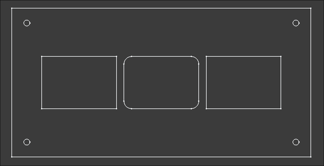
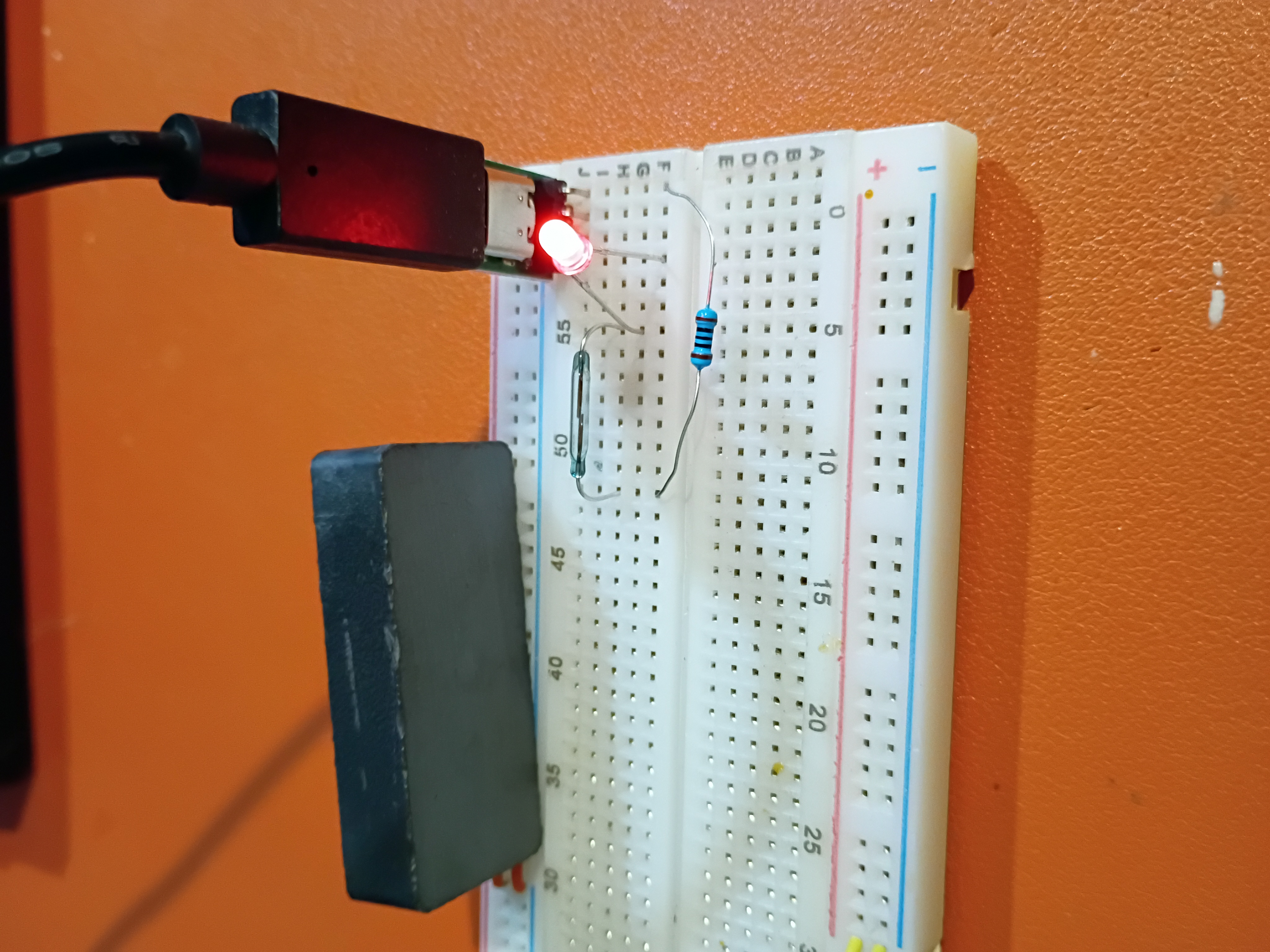
I also tested a USB-C power supply and a Reed switch as an alternative to the Hall effect sensor. It is extremely sensitive.
I adapted the Atmega328P C code to control the 4x separate 7-segment displays.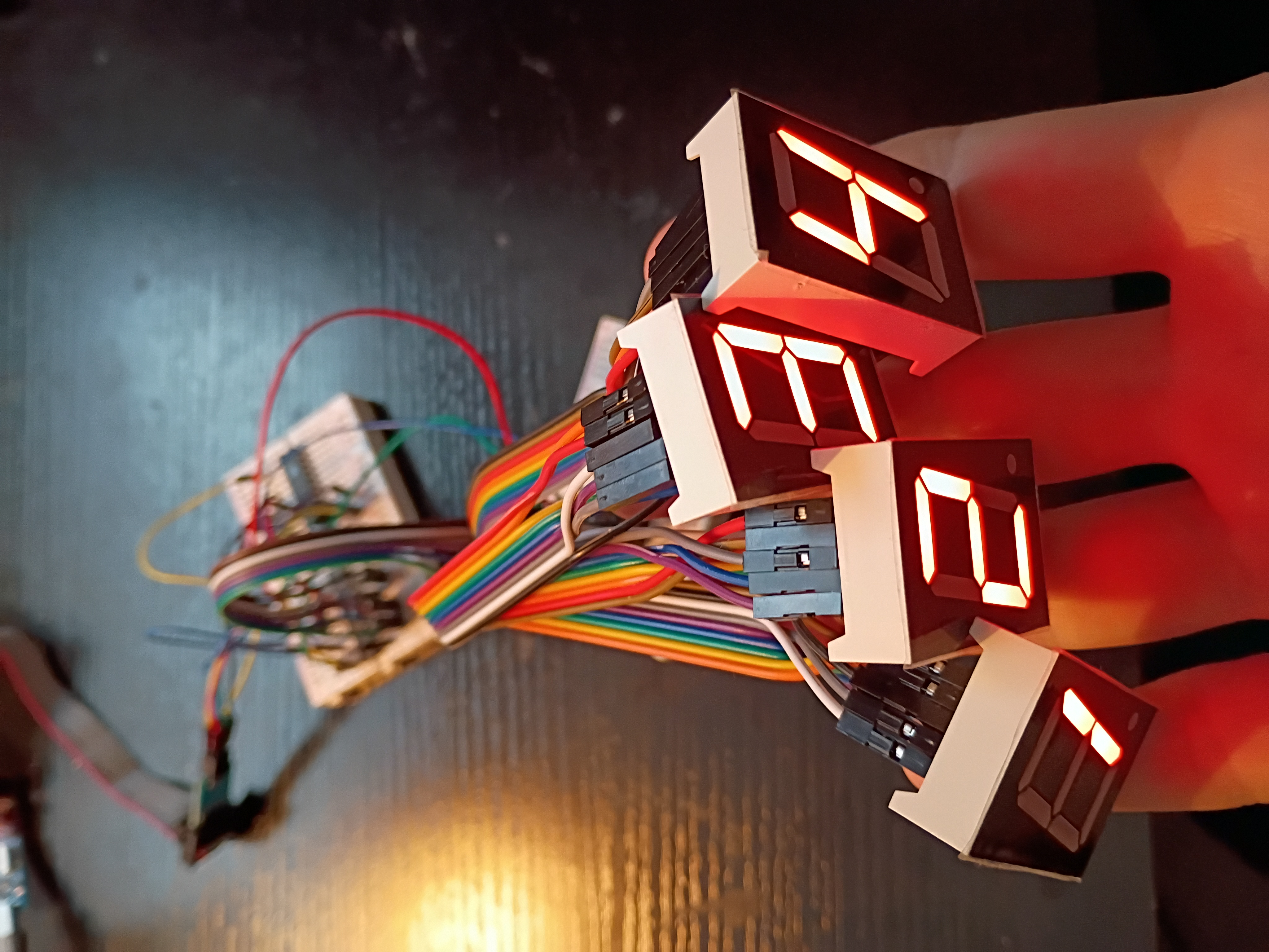
I hooked up 4x 7-segment displays to the MAX7219 IC for testing tomorrow.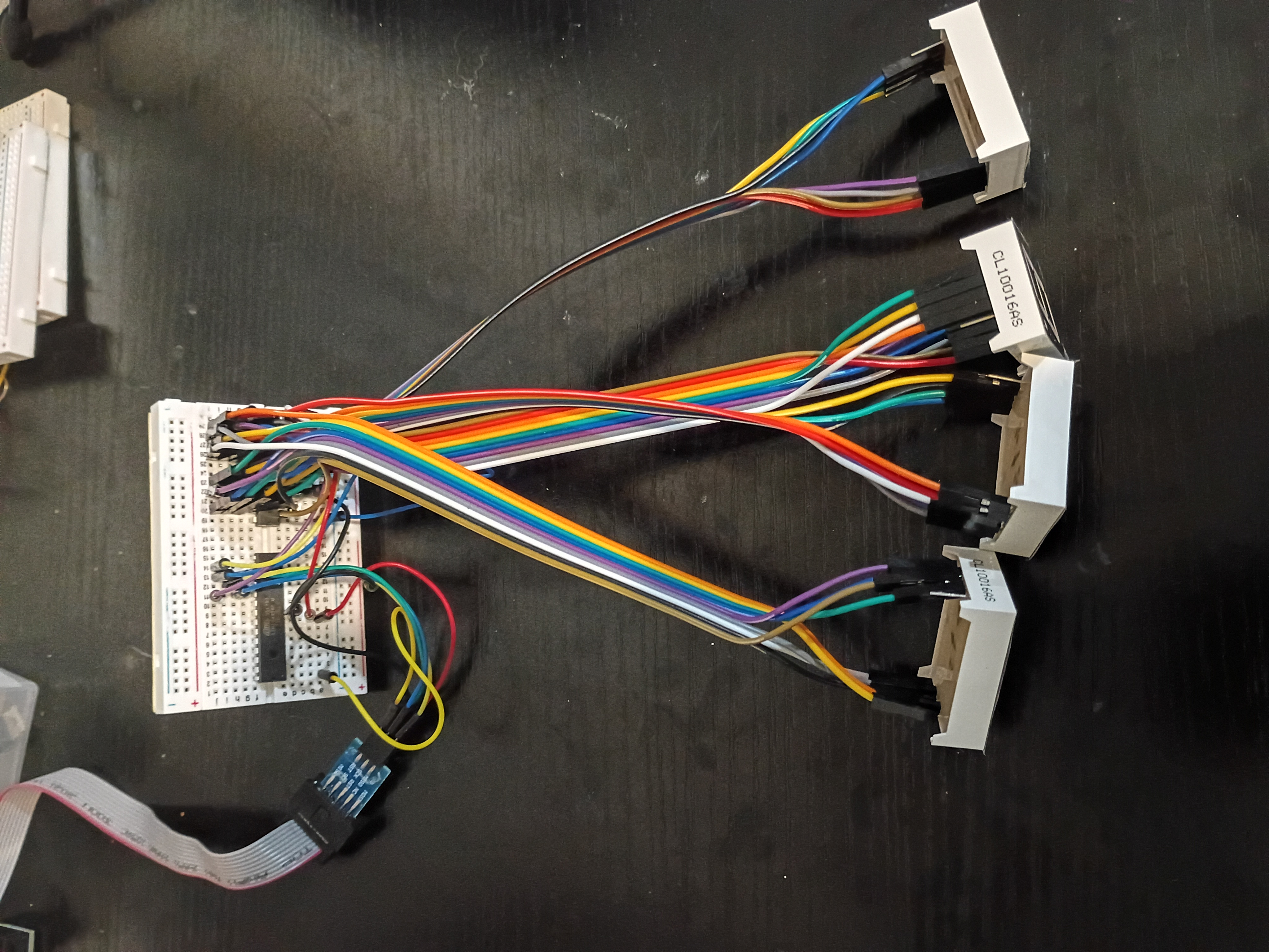
After much debugging (2 days), I realized I had the Rset resistor on the MAX7219 jumping to GND instead of 5V. I thought for sure it was supposed to go to GND. Either way, we have this Atmega328P C code to control a 7-segment display over what is essentially SPI.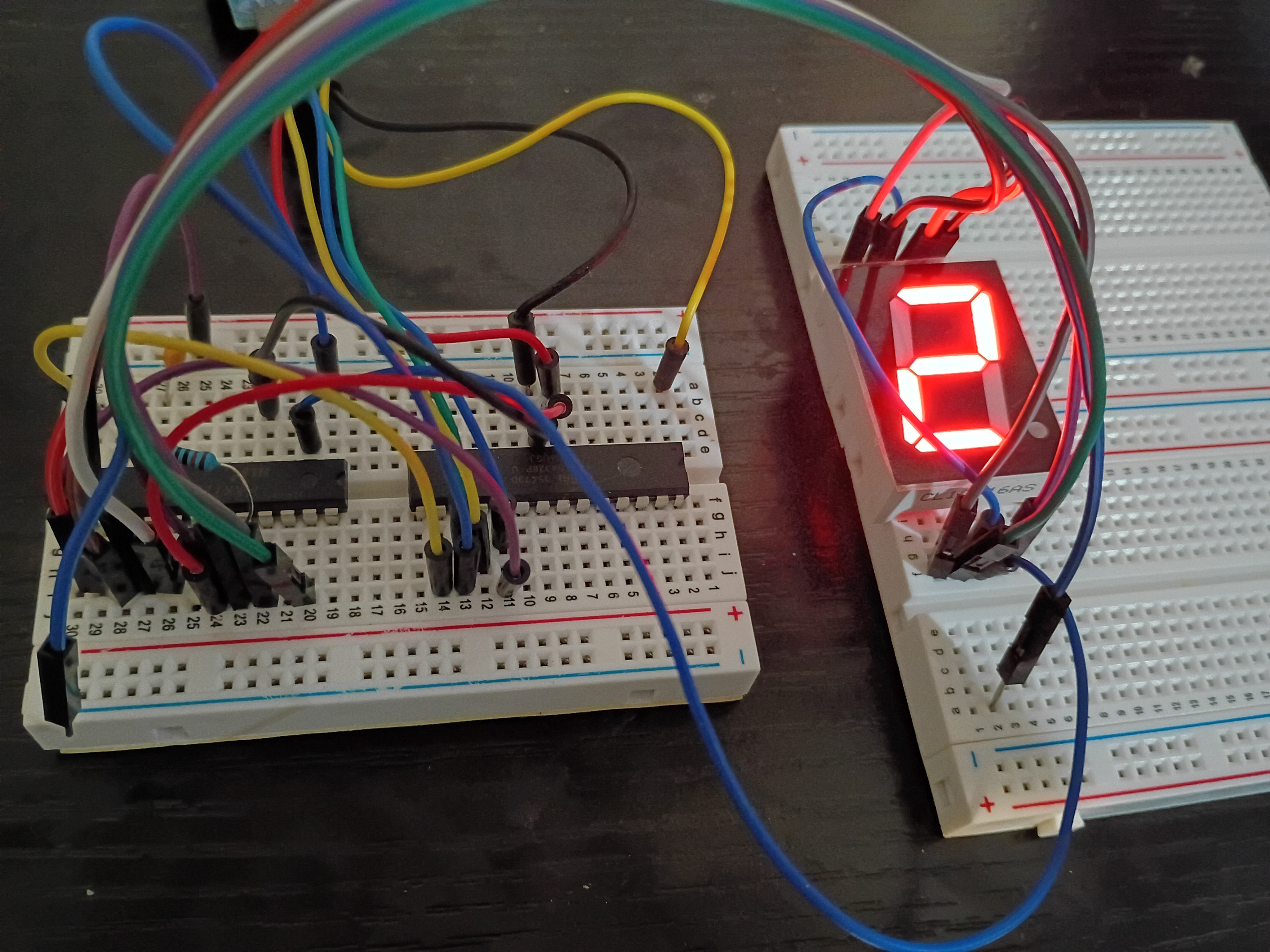
I attempted to implement a circuit to control a 7-segment display using the MAX7219 driver IC, but unfortunately my 7-segment displays are all common-anode, so they are not trivially compatible. While I source common-cathode ones, I tested a basic digit Hall-effect circuit using an LED.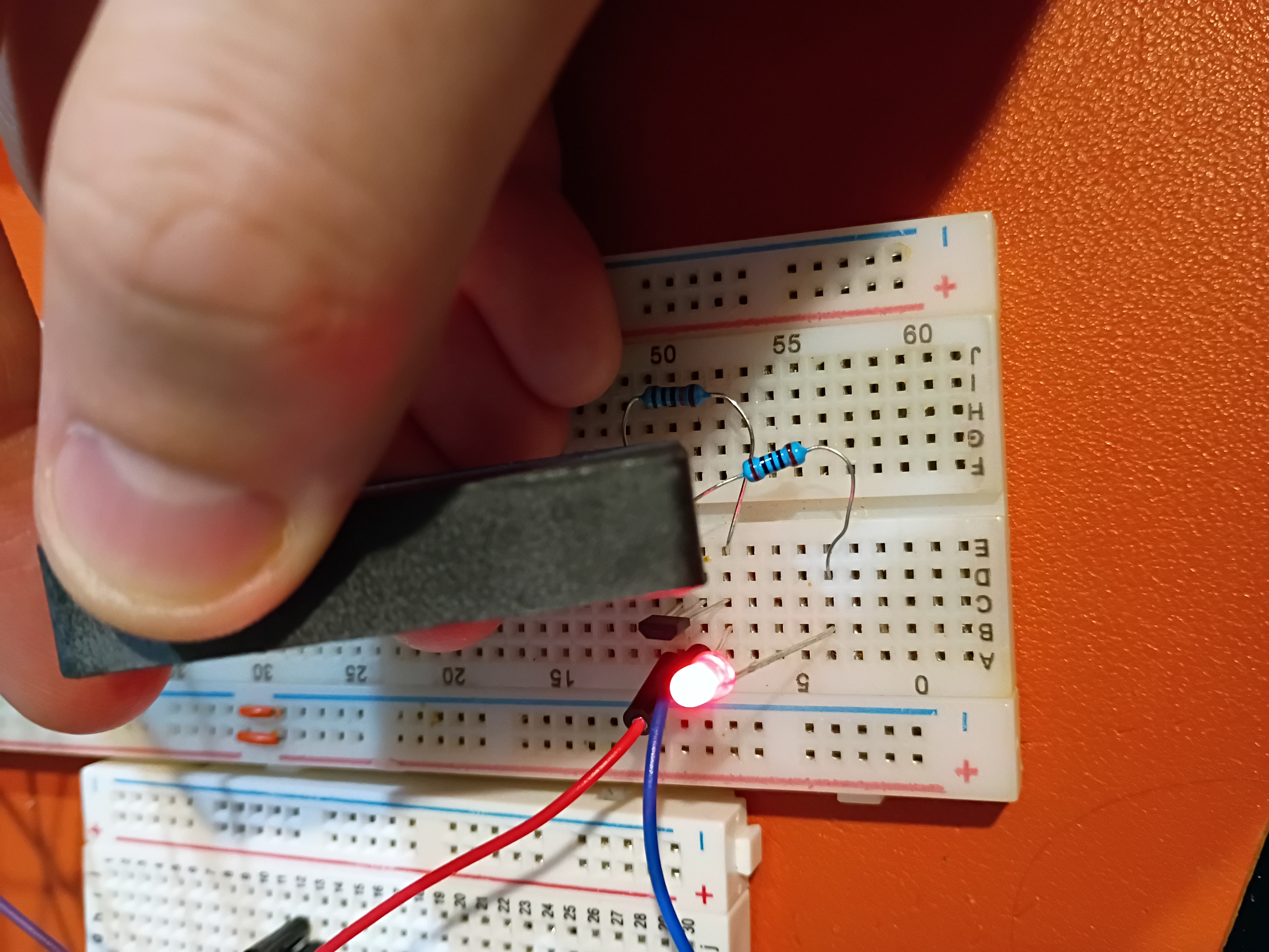
I tested control of an RGB LED with an Atmega328P here.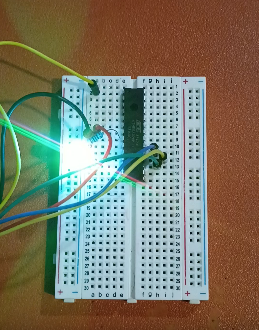
In response to RFP004 - MM1, two candidate 'microcontroller experiences' were proposed in submission xMM1.