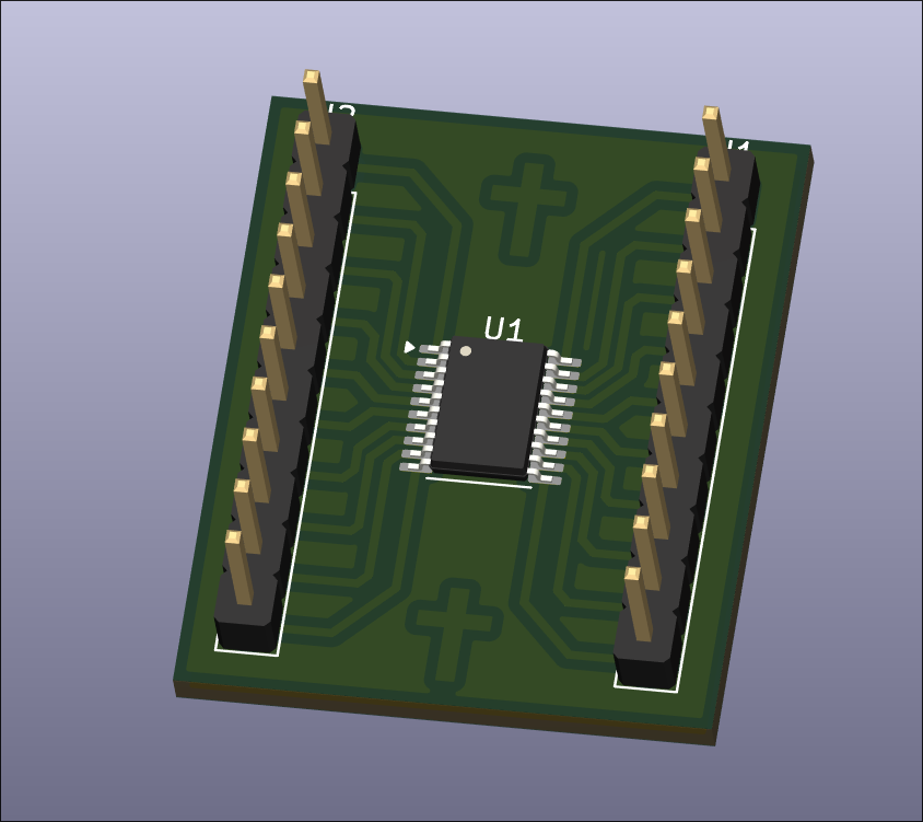
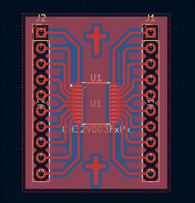
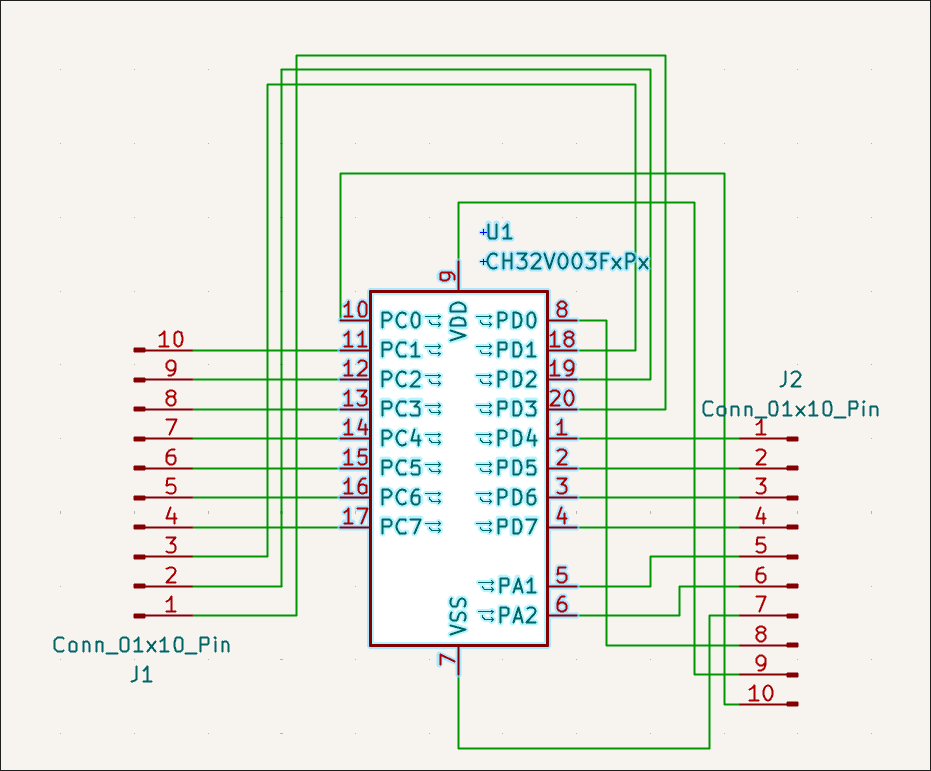
Designed CH32V003F4P6 (TSSOP-20) breakout board.
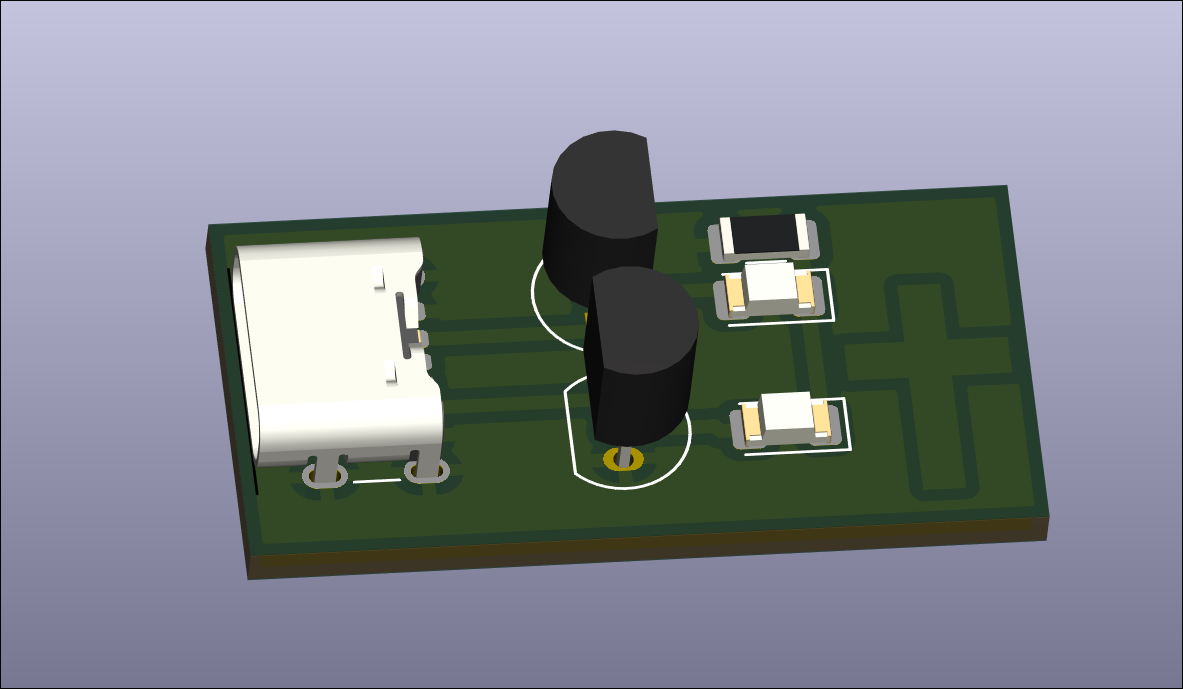
Designed Hall Effect magnetic switch test circuit for future magnet-controlled input sensitivity evaluations. 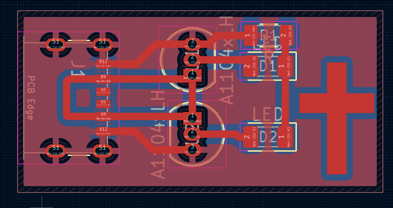
Designed reed switch test circuit for future magnet-controlled input sensitivity evaluations. 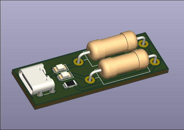
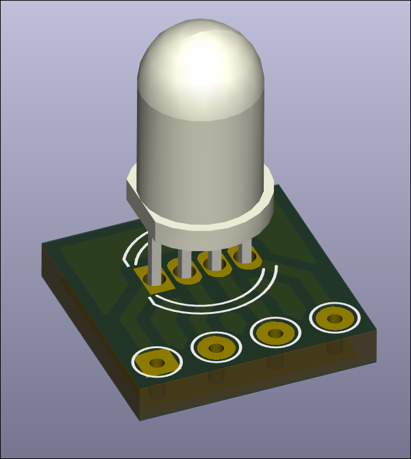
Designed RGB LED mount and breakout board for in-house fabrication. Board size is 10x10mm. 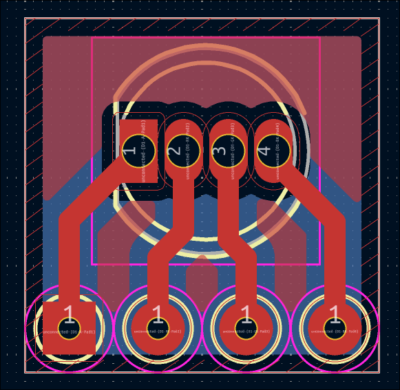
Painstakingly filed the circuit board to size to fit into the box assembly. I really need to stop being so 'conservative' on the board snapping. Or just put a lot of extra clearance in these boxes. 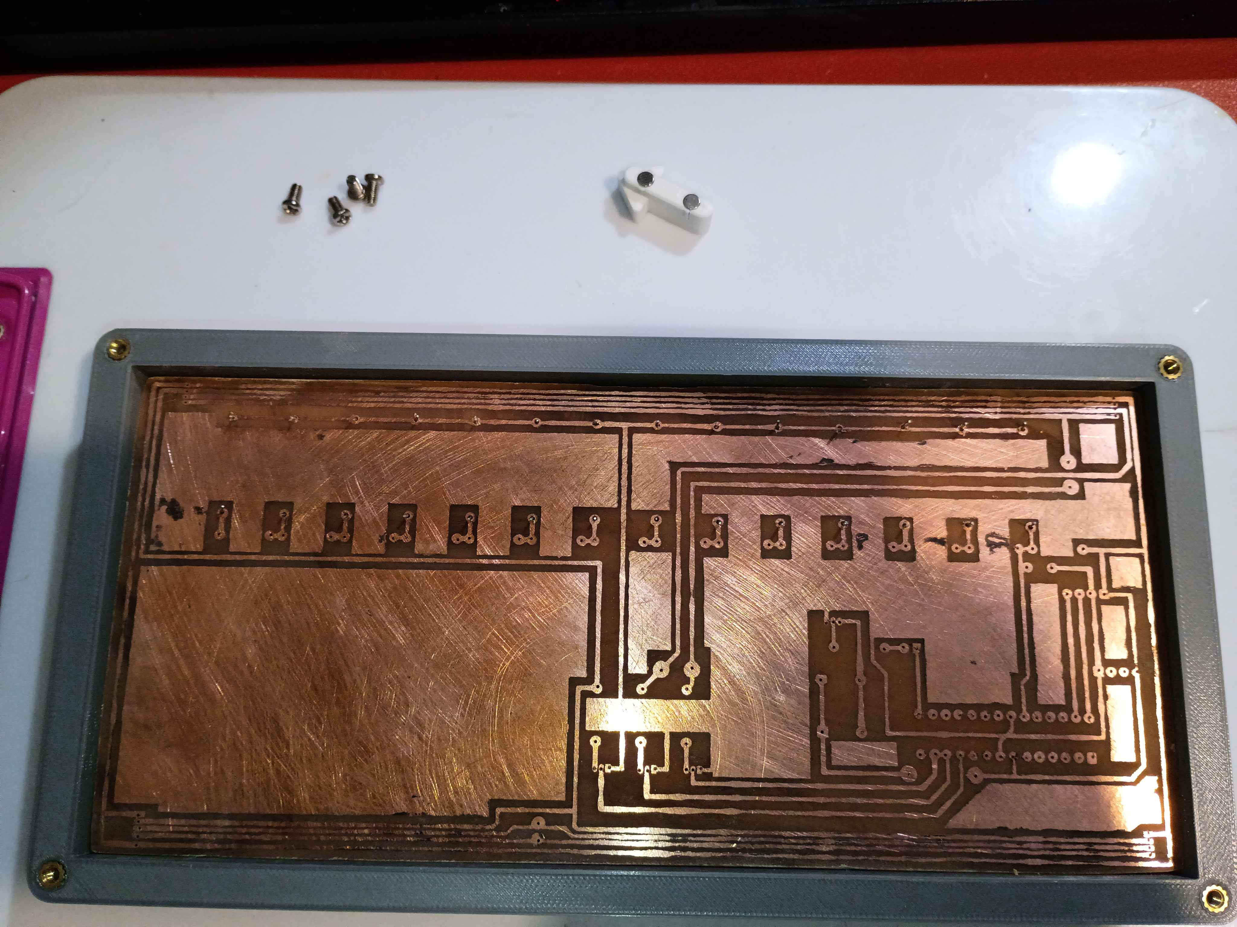
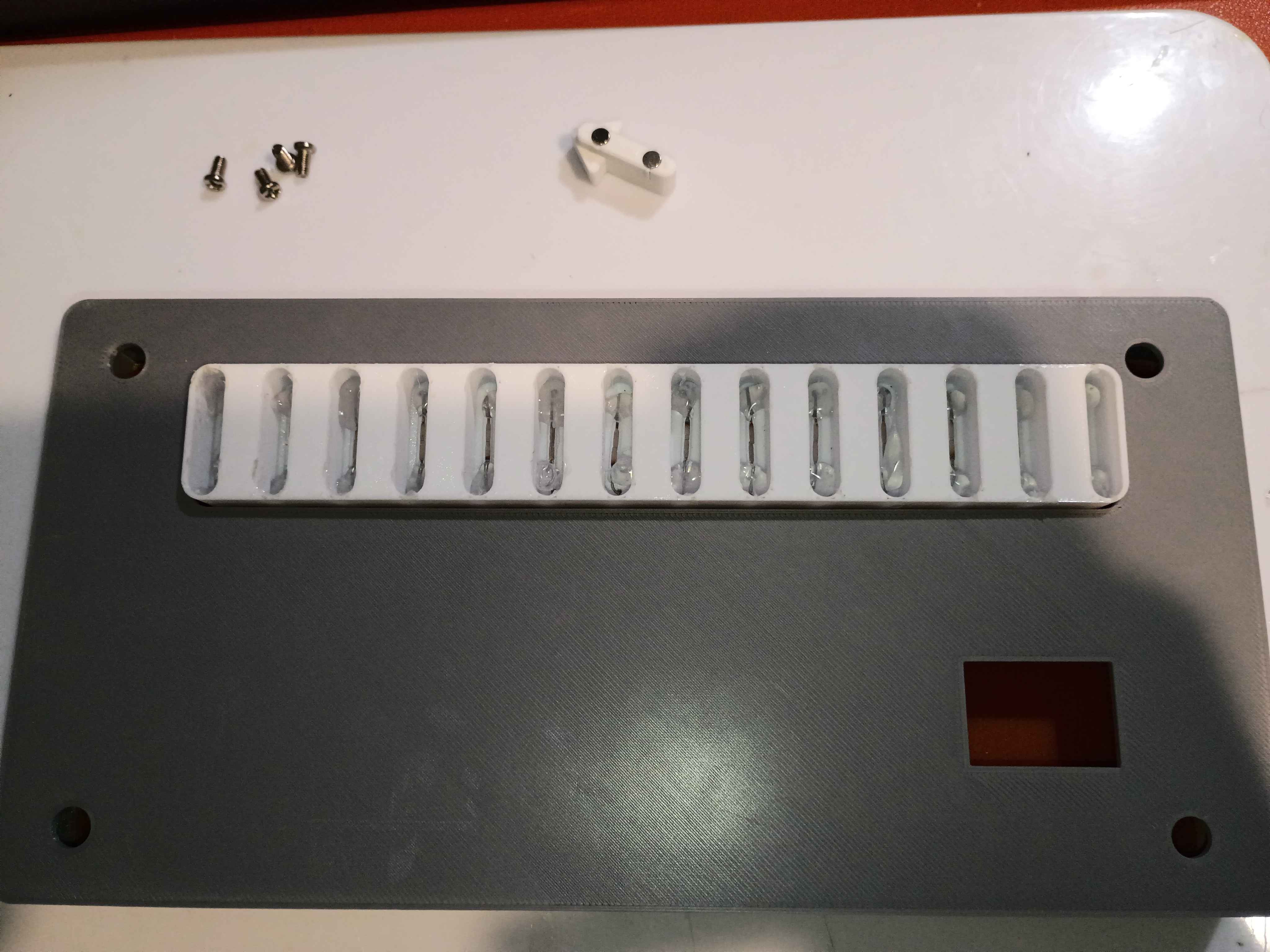
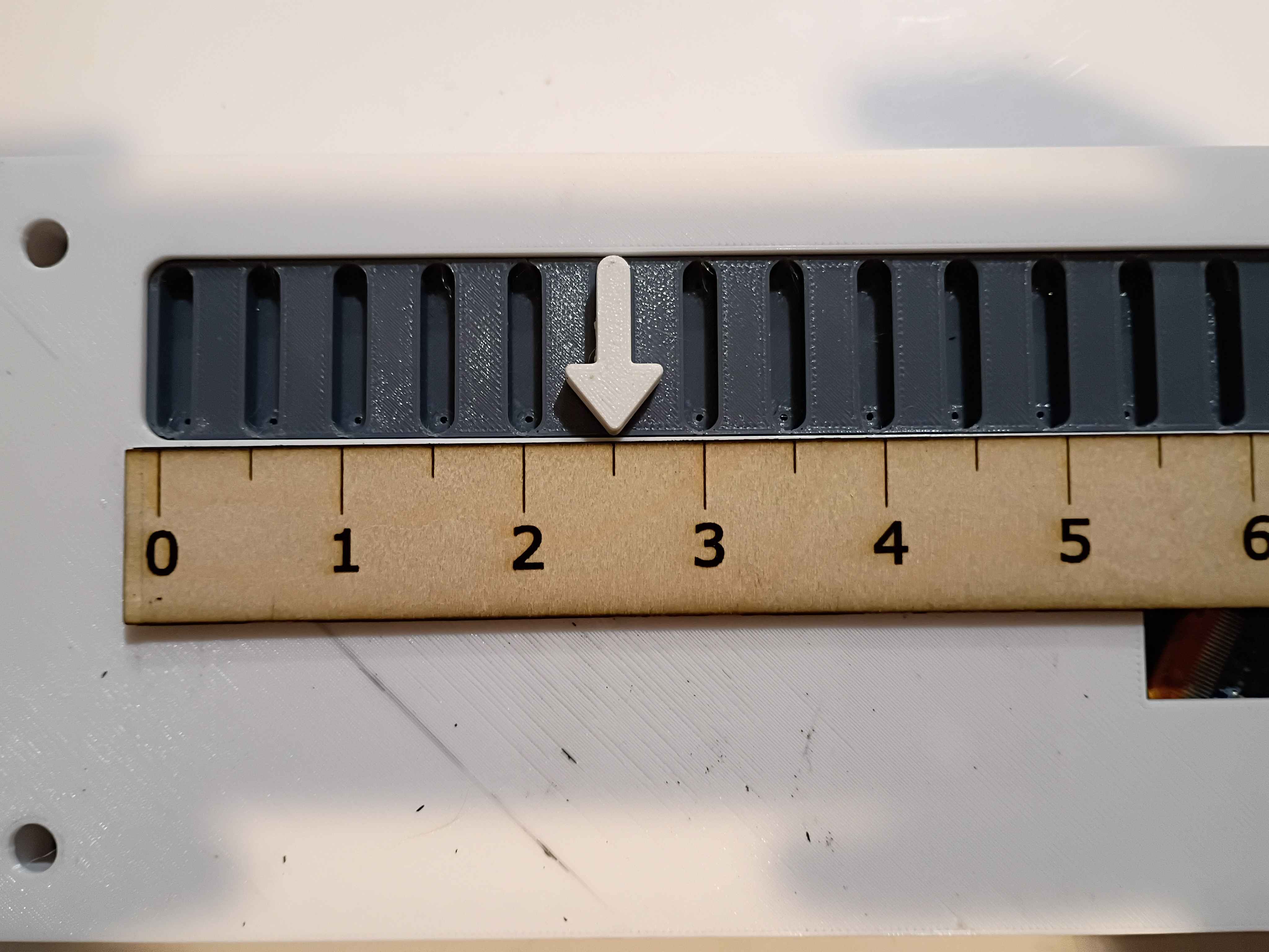
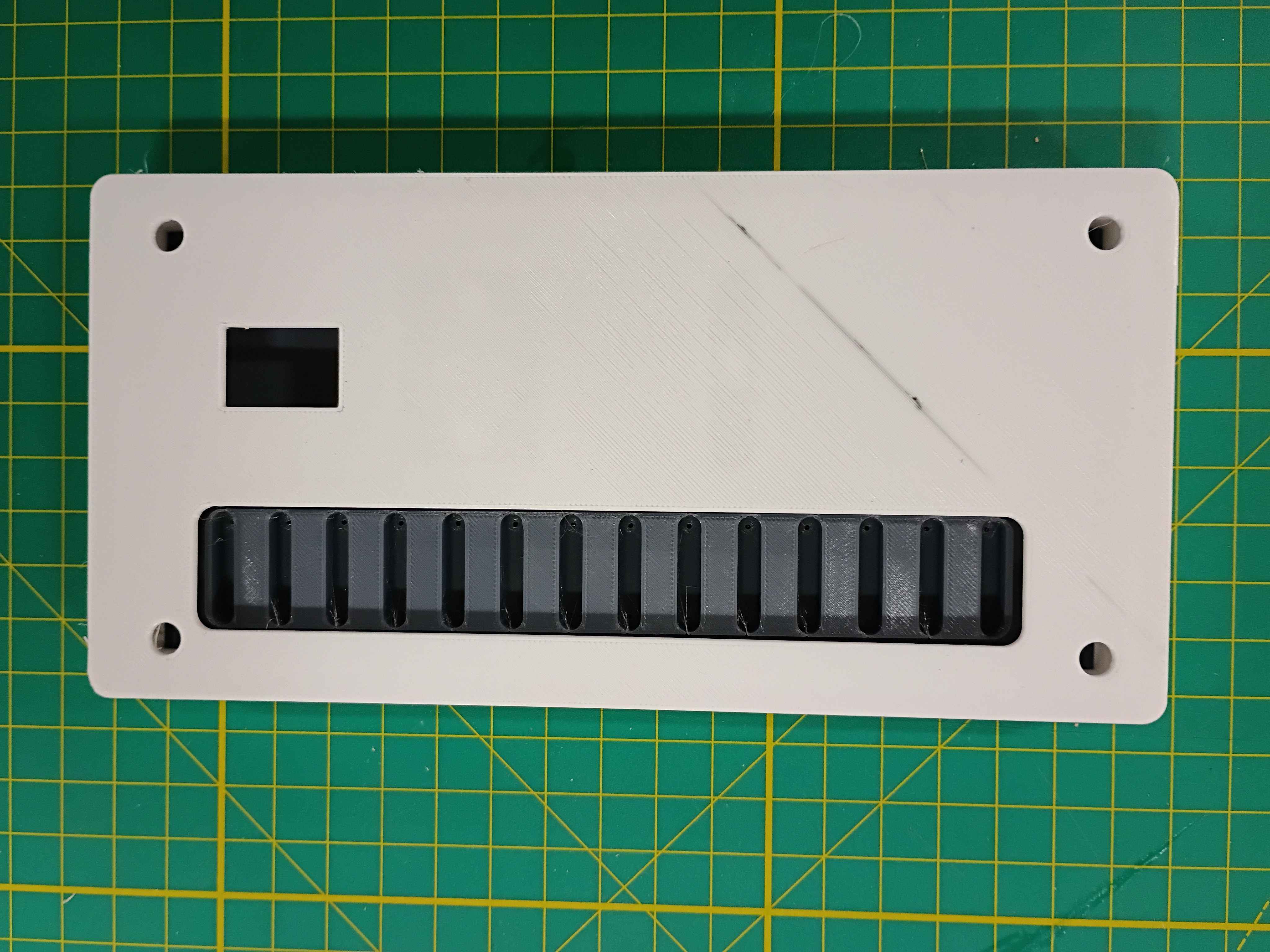
Reprinted slotted component with deeper slots. Bent and installed reed switches, put a dab of glue on each lead to keep them in place, and then installed the entire slot assembly onto the PCB. After testing with the magnetic input device, the slots are the perfect depth to prevent all false positive readings. 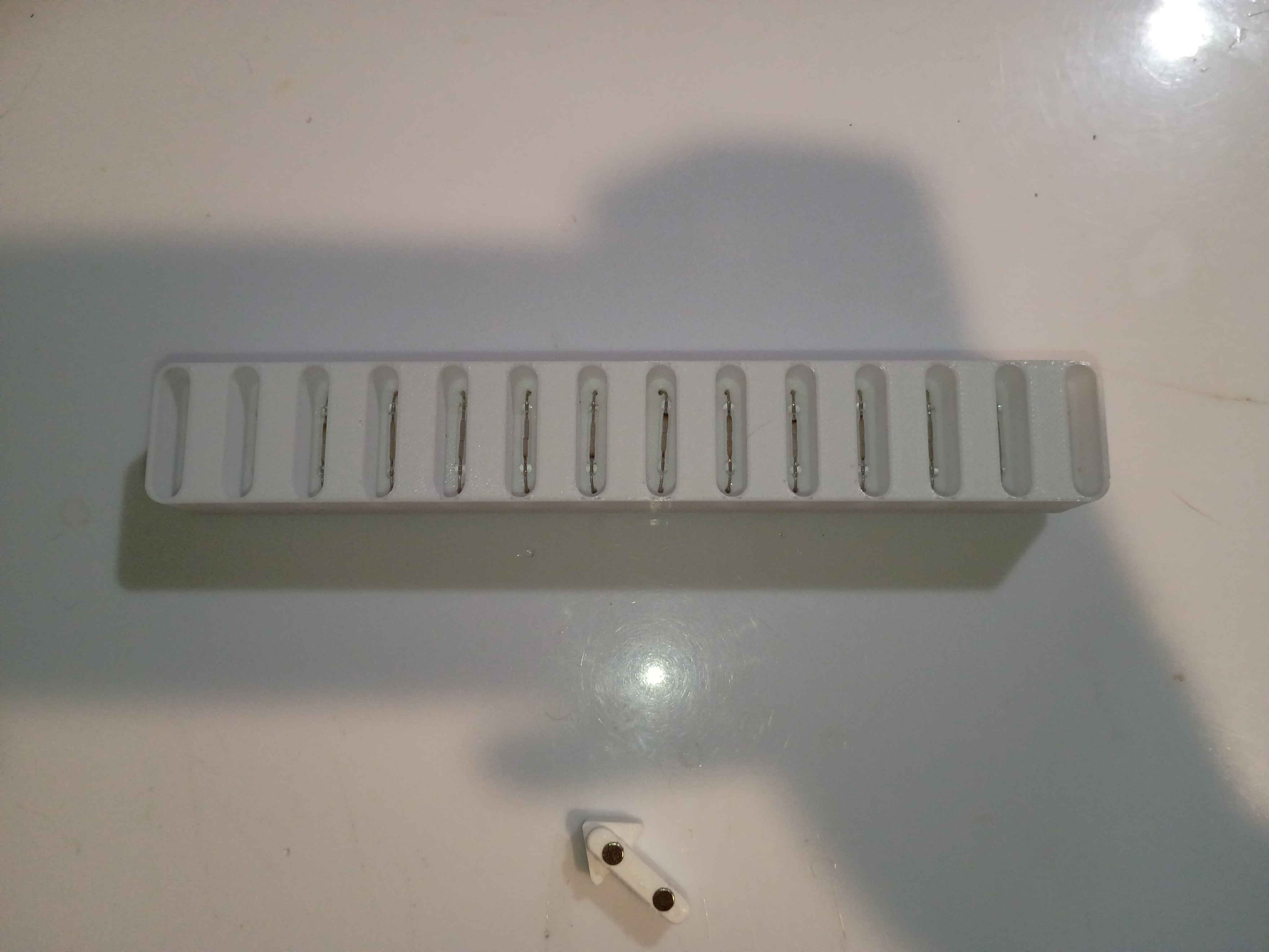
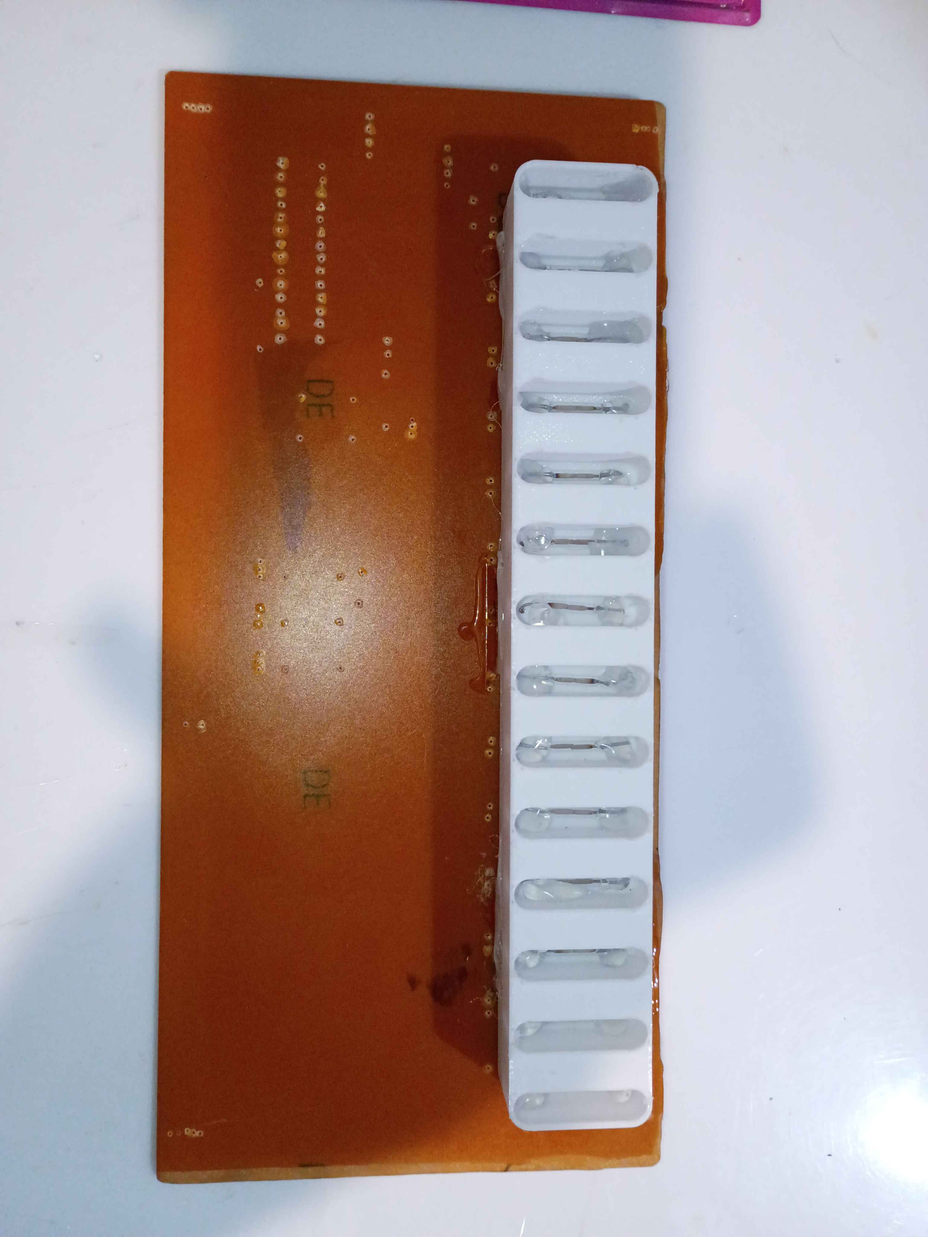
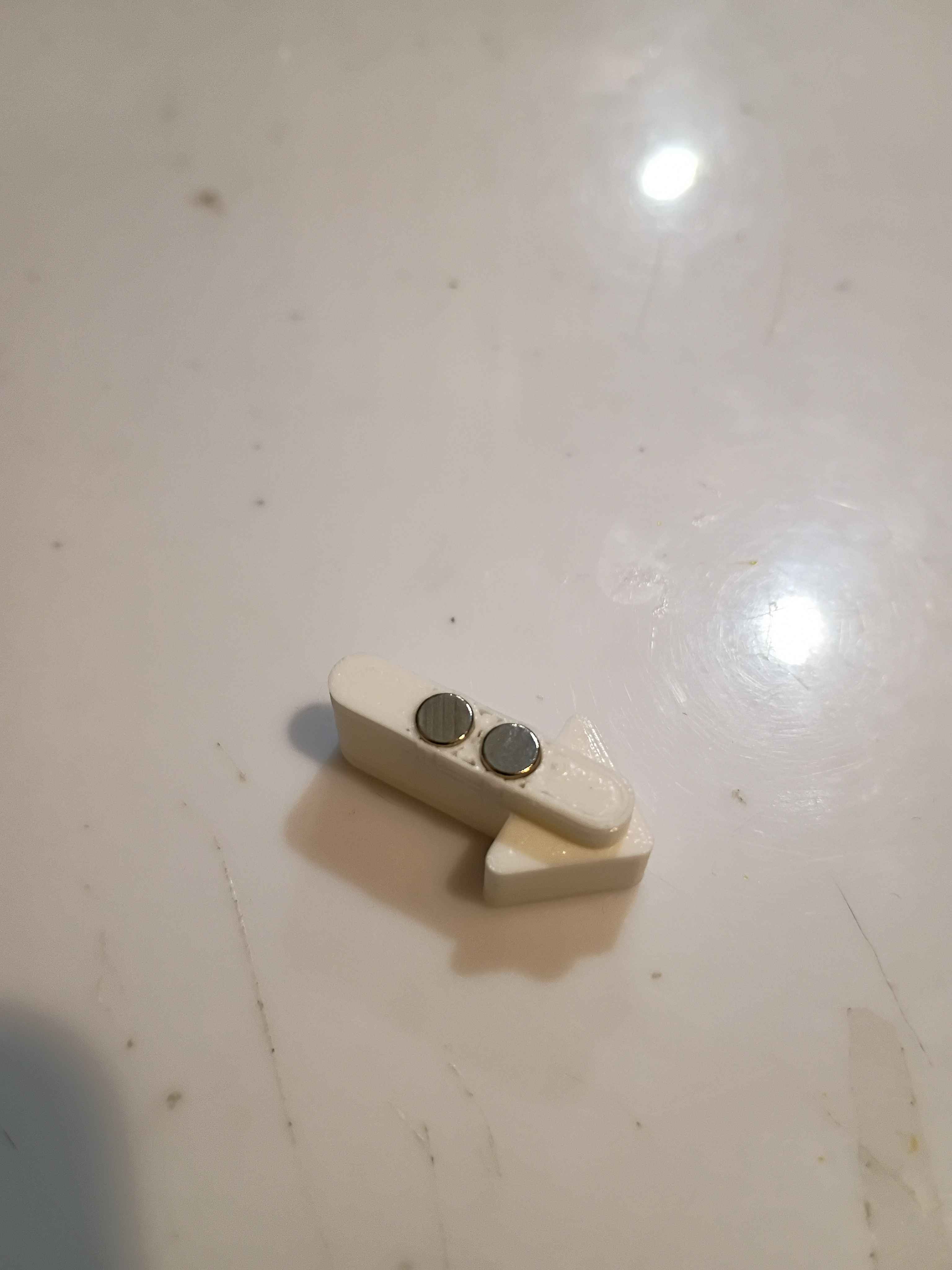
Tested enough configurations of the reed switch to understand the ideal part orientation. Ideally two opposite magnets should be oriented into the ends of the glass tube, perpendicularly, and the flat faces of the reeds should also be facing the magnets. Updated the 03010-006 input device to handle this new spacing and printed for a successful test. Also because this configuration is so sensitive, to prevent false positives, I updated the 03010-003 input slot component to recess the reed switches 5mm lower down. That updated CAD file is uploaded for printing tomorrow.
Reprinted box components and reinstalled heat set inserts. Drilled 0.6mm holes in etched PCB. Tested some configurations for the reed switches. 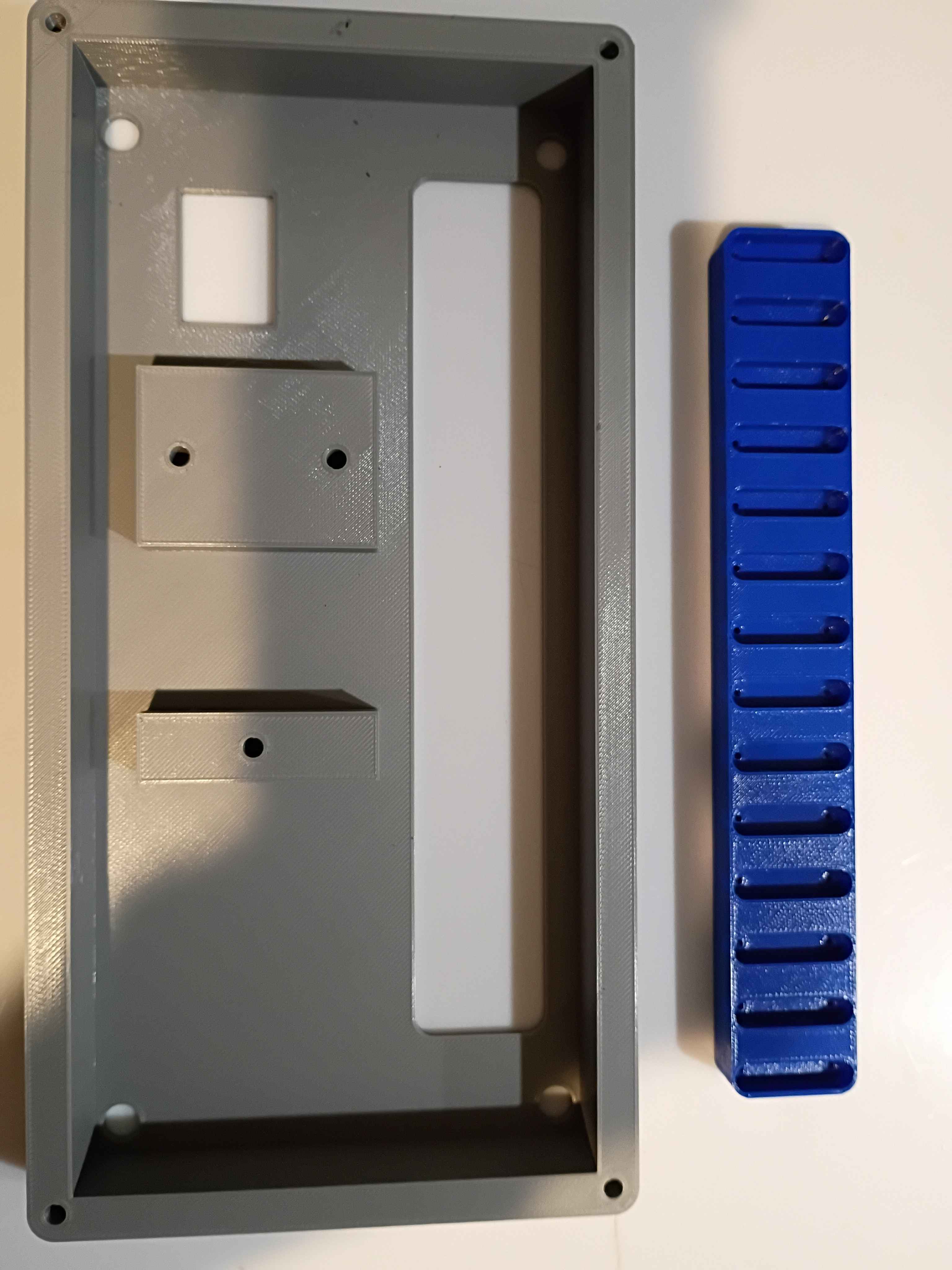
Updated .3mf files in GitHub repo for printing at work tomorrow on the large format printers. Updated and printed the input device to accept an 1/8-inch dowel for a handle, among other slight adjustments. 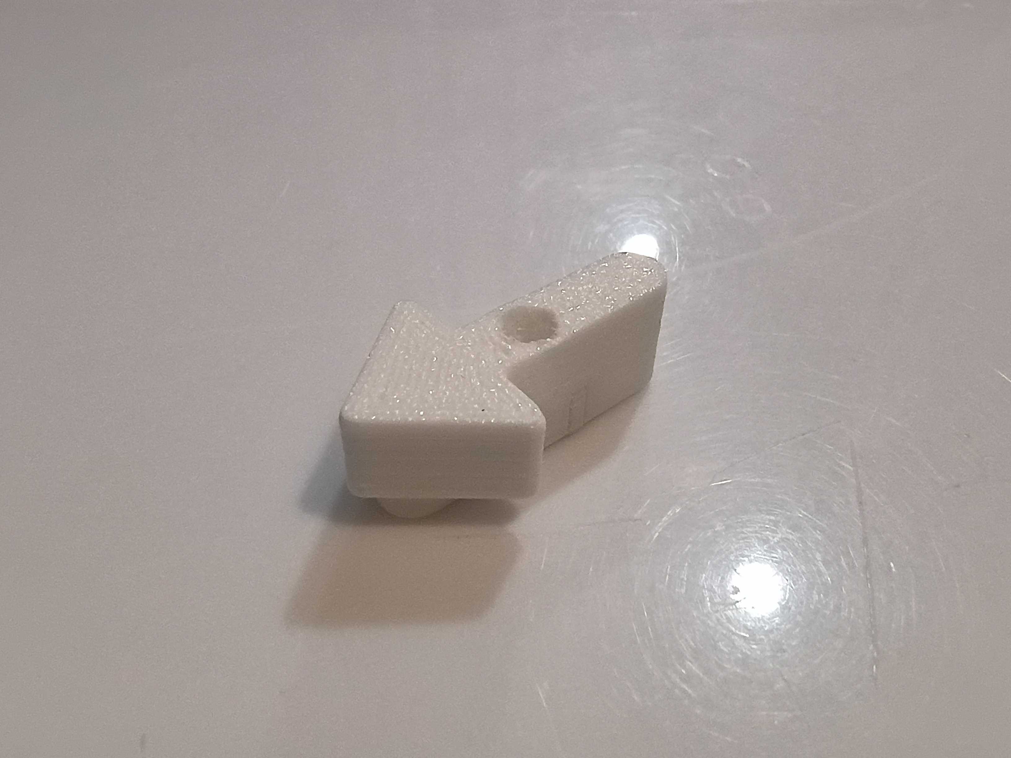
Designed and printed a (very small) magnetic input device. After some preliminary test fits, I decided that the slots in the slotted reed switch assembly needed to be slightly wider, so the entire assembly was redesigned and will be printed at work this week. 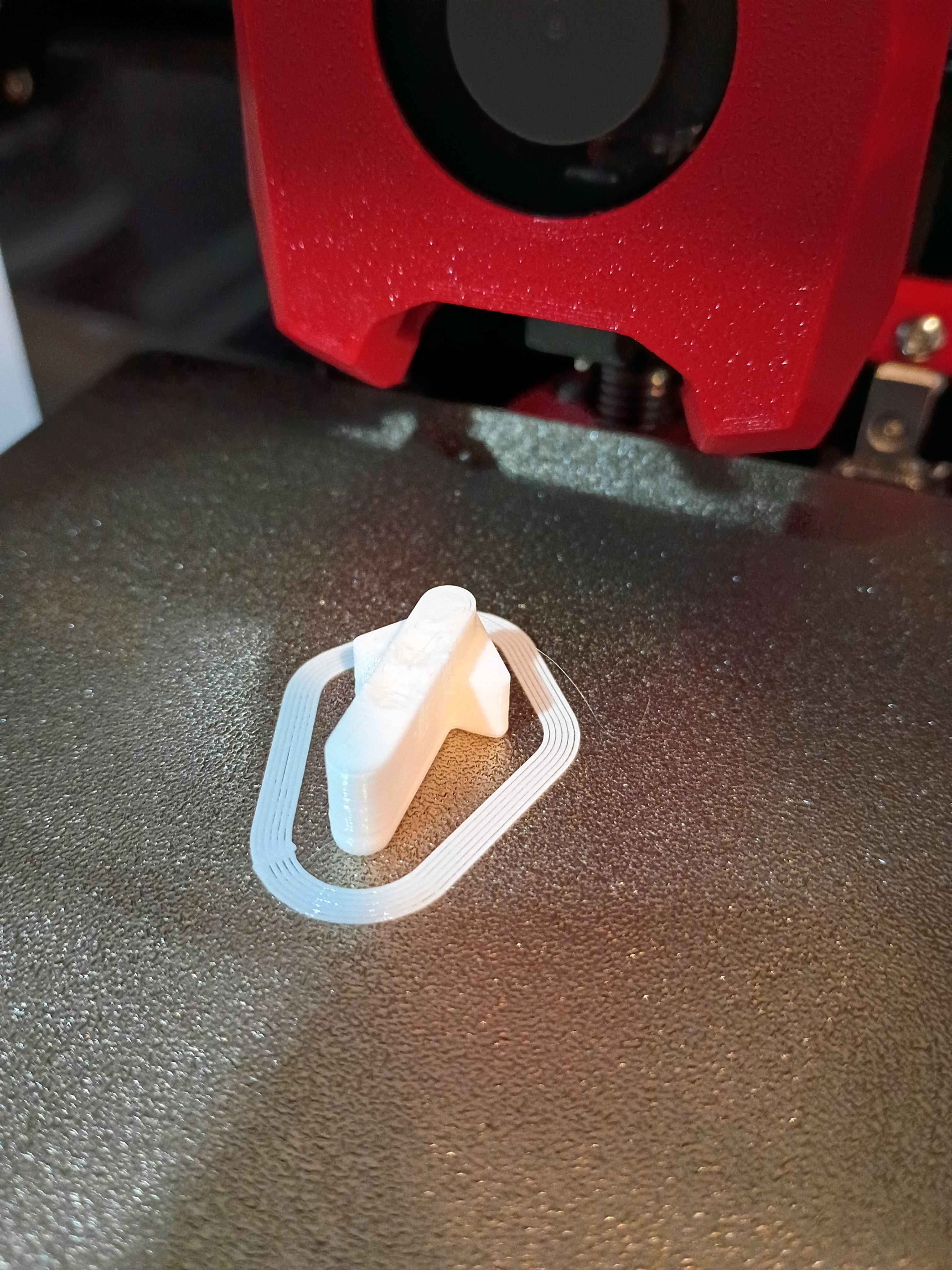
Laser cut some 03010-001 rulers. 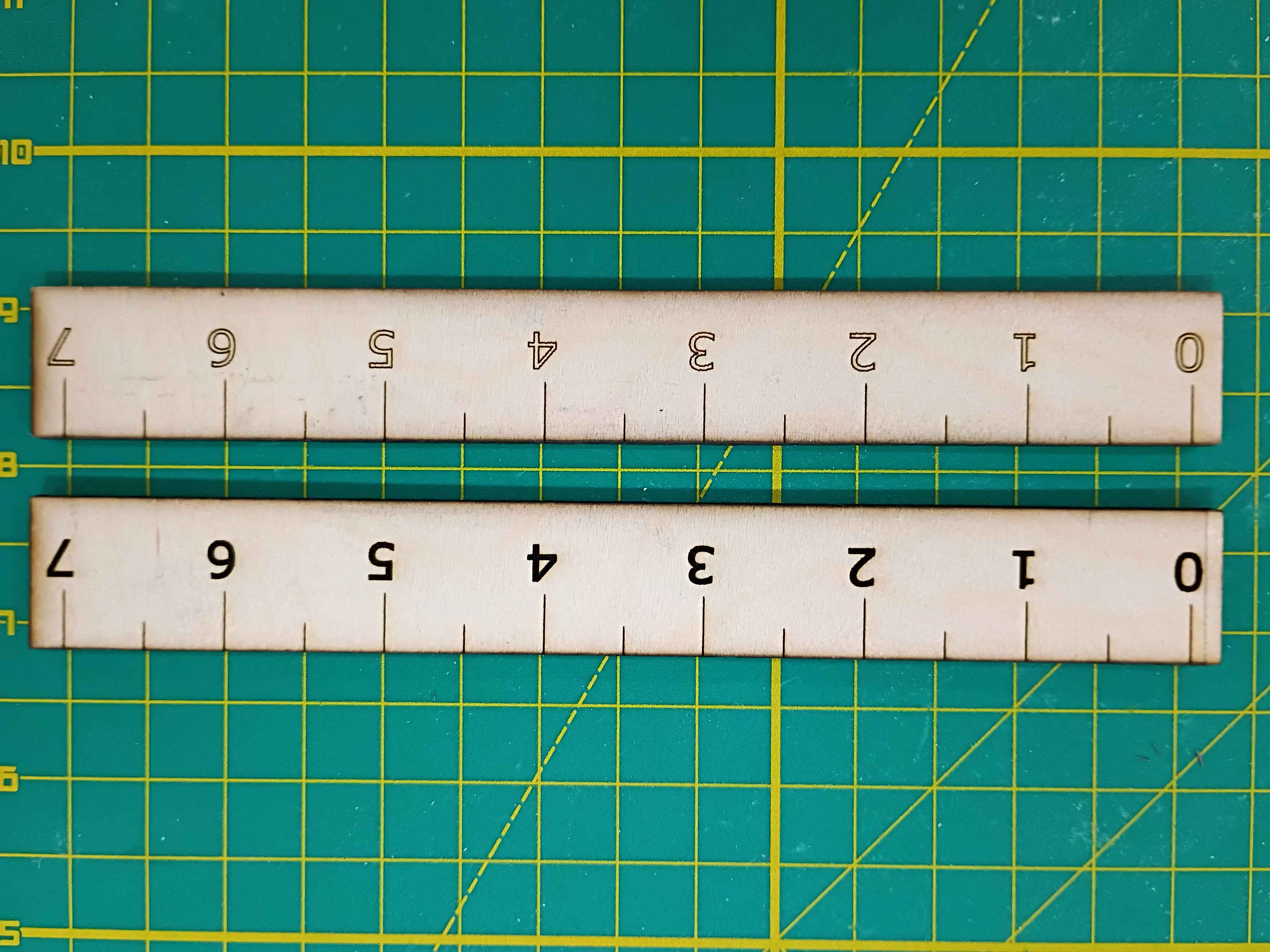
Tested box layout. May need to reprint the white body piece with the OLED cutout slightly lower. 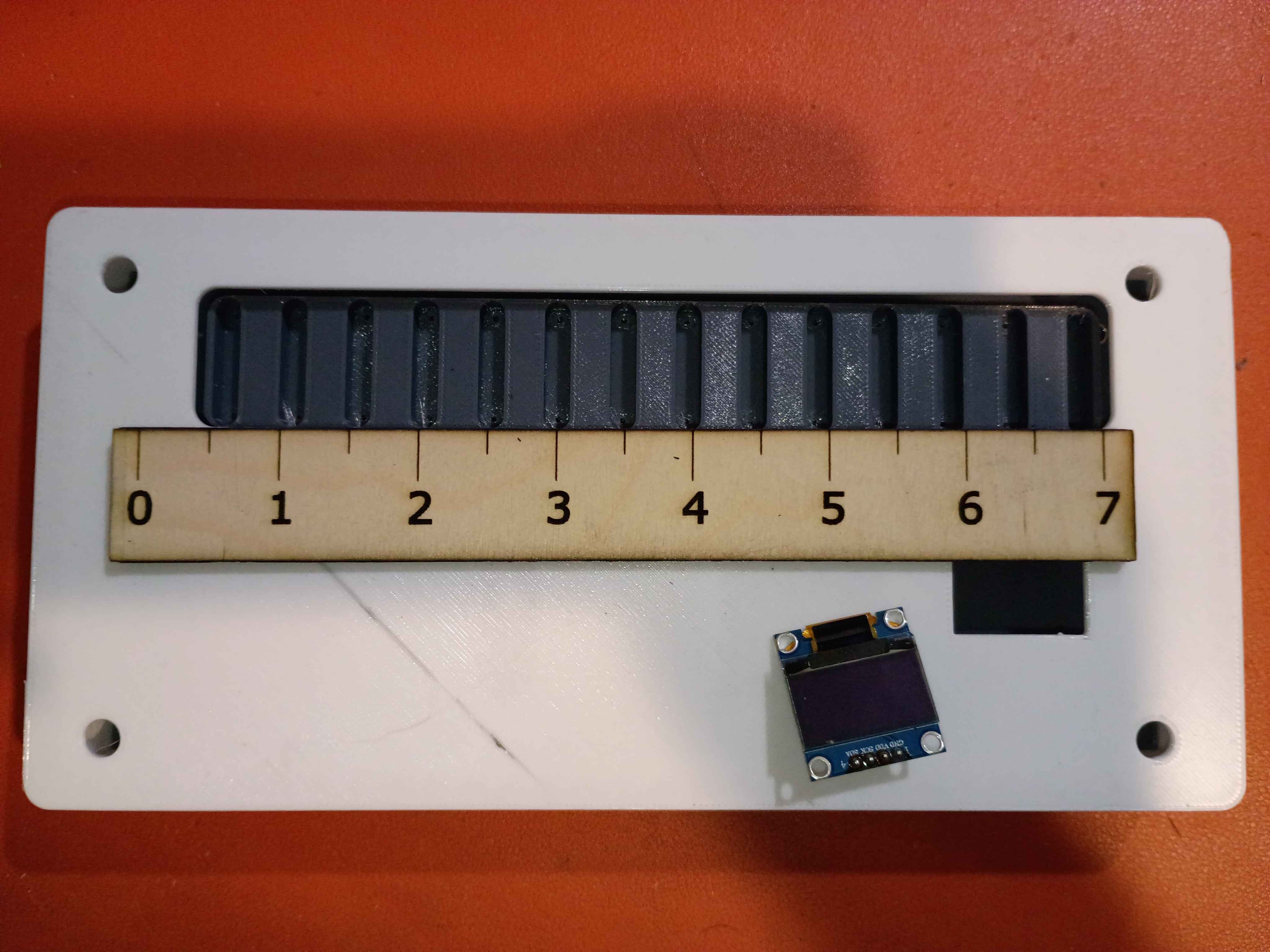
Attached rubber feet to bottom. 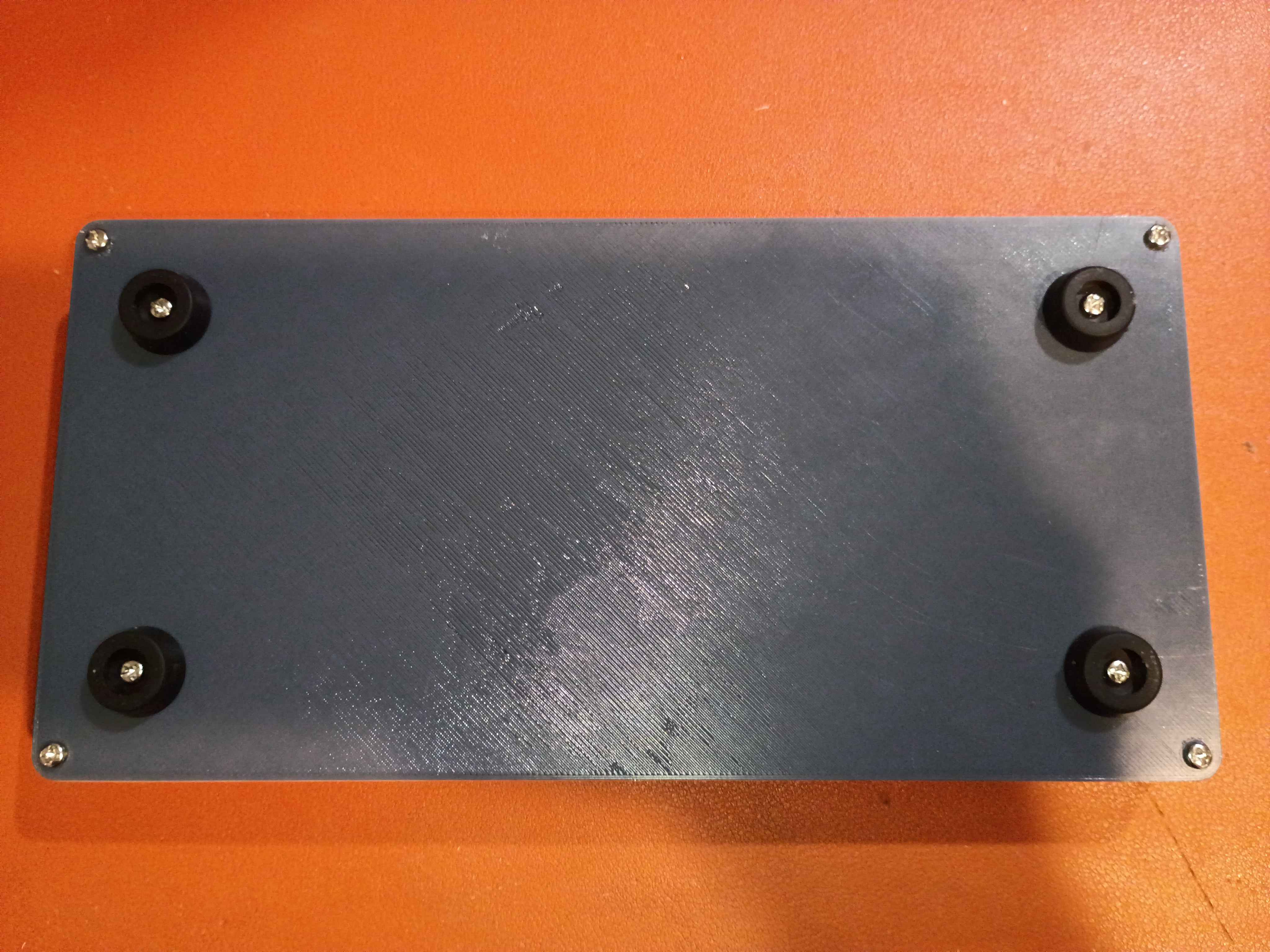
Tested various Ferric Chloride etch-resist options on a scrap piece of copper clad. 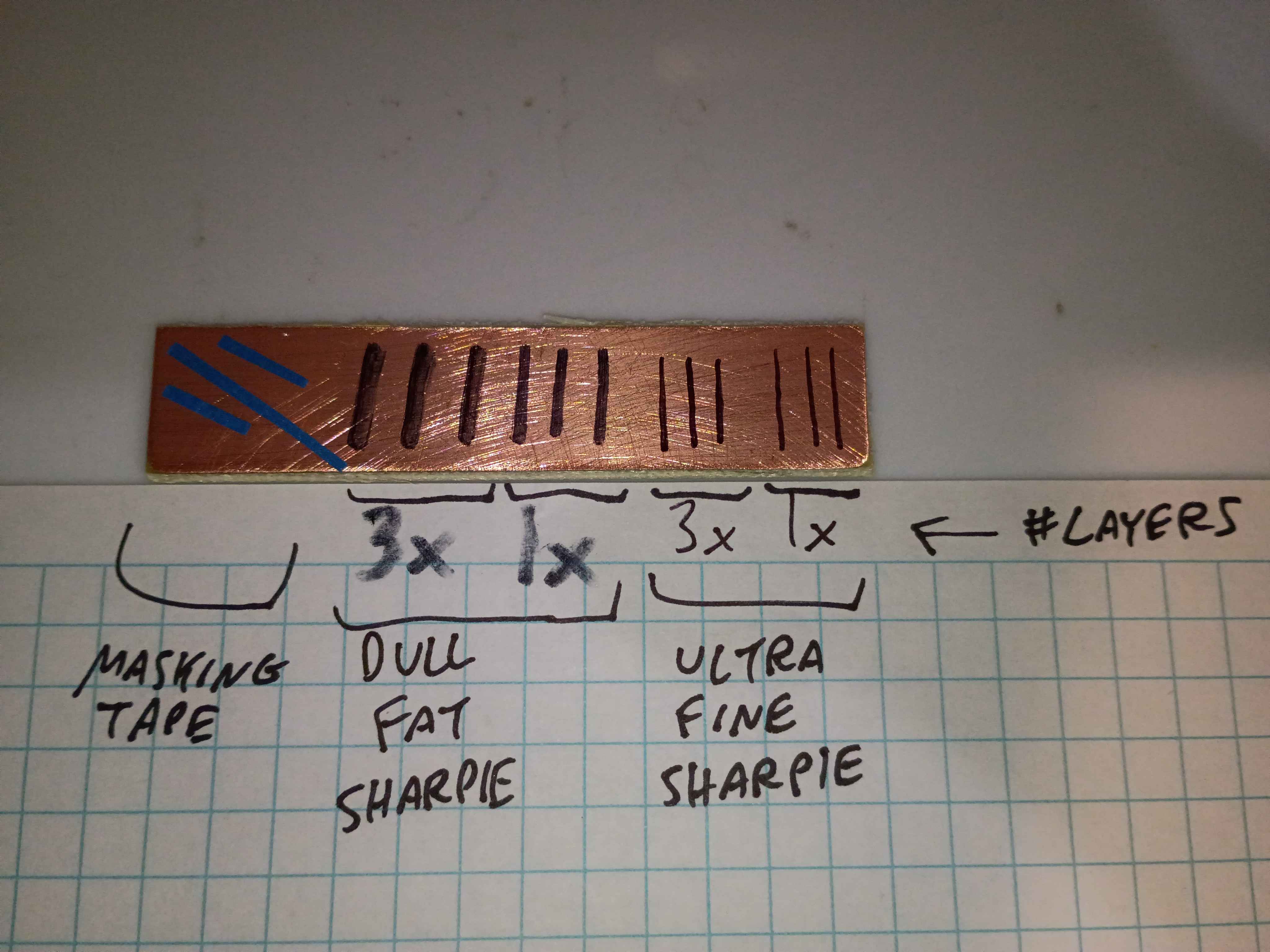
The finest and best solution is multiple coats/layers of the Ultra Fine Sharpie, or masking tape for large rectangular areas. 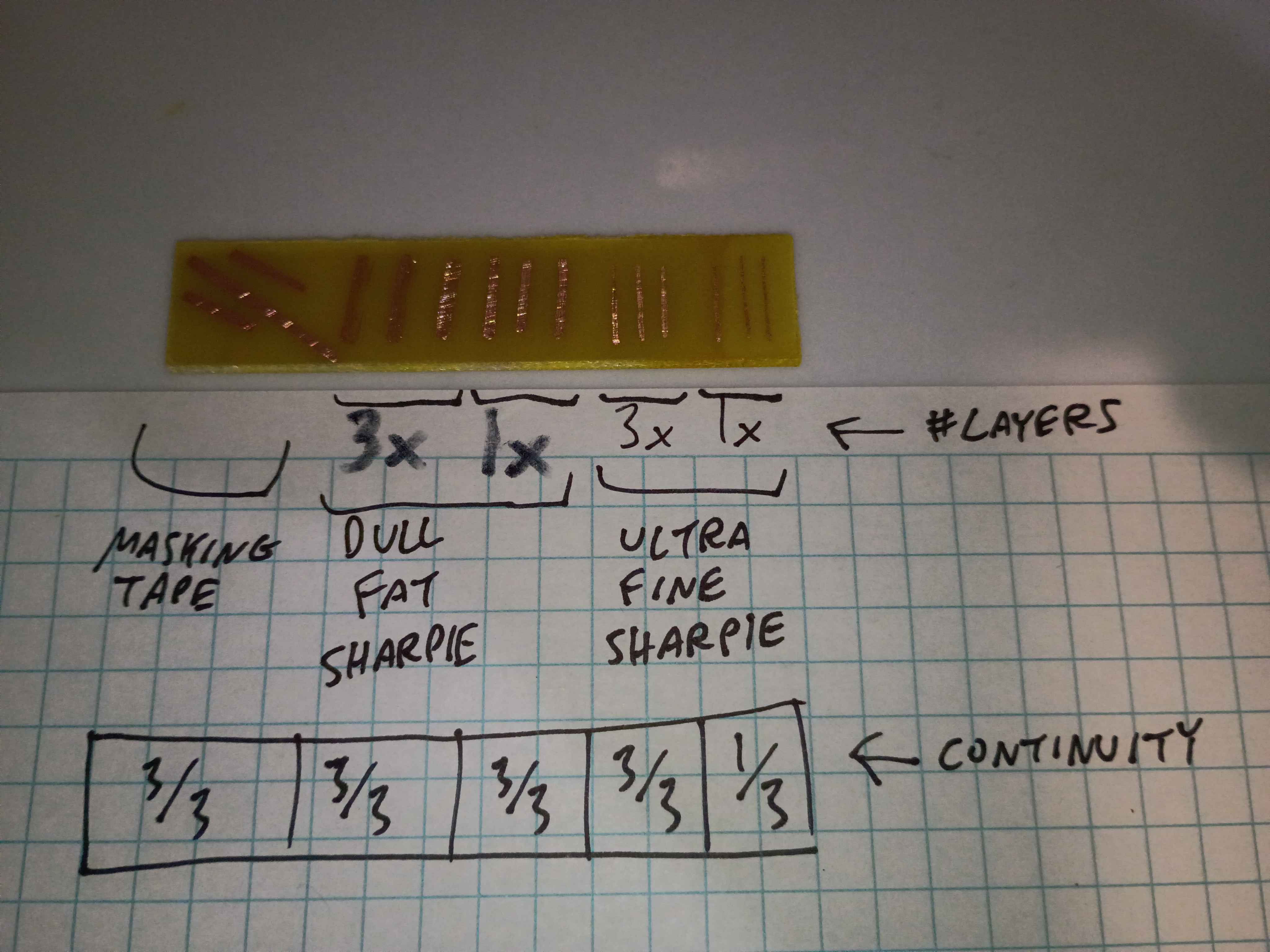
Used these solutions to repair minor issues in the toner-transferred copper mask. 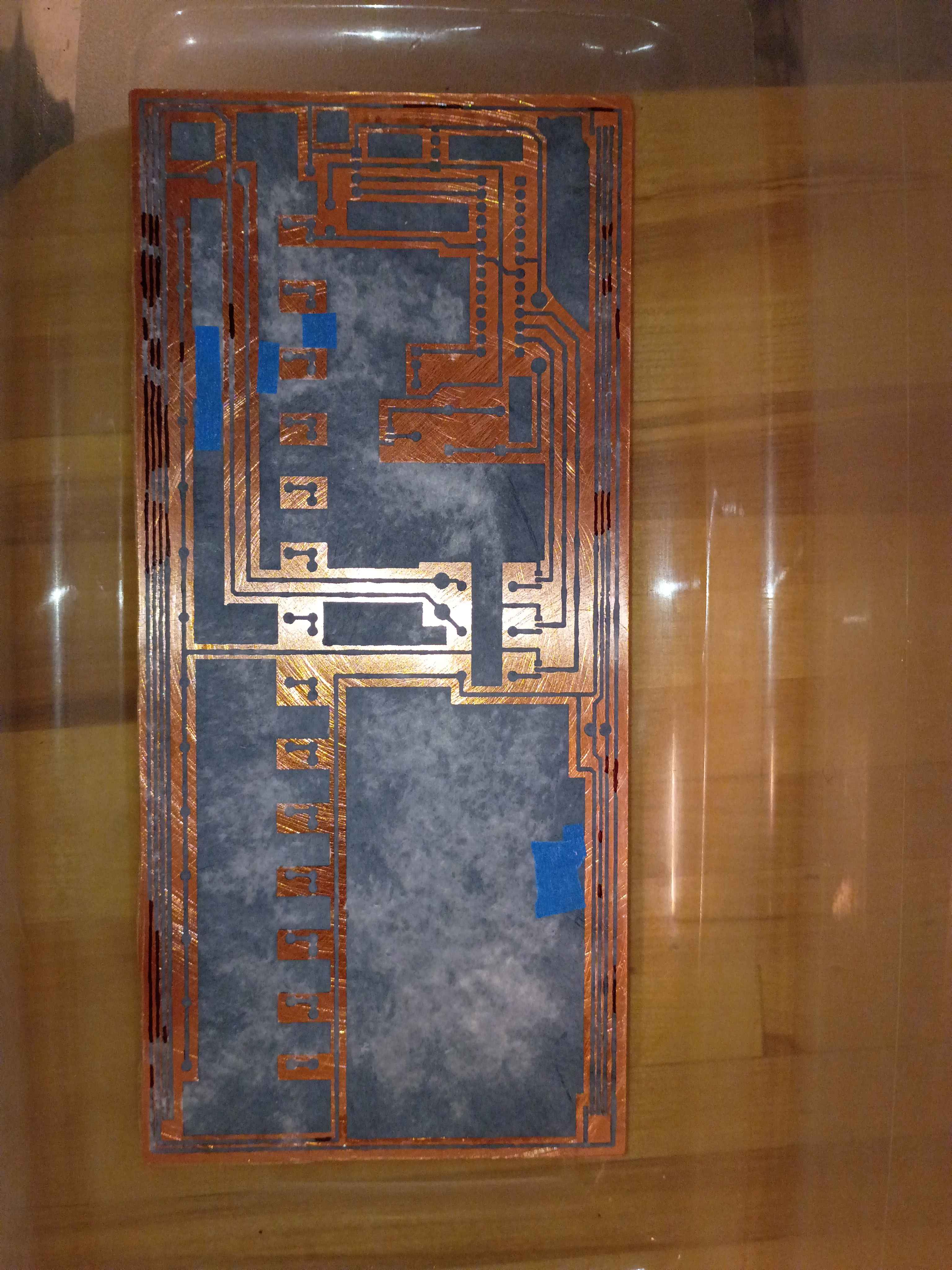
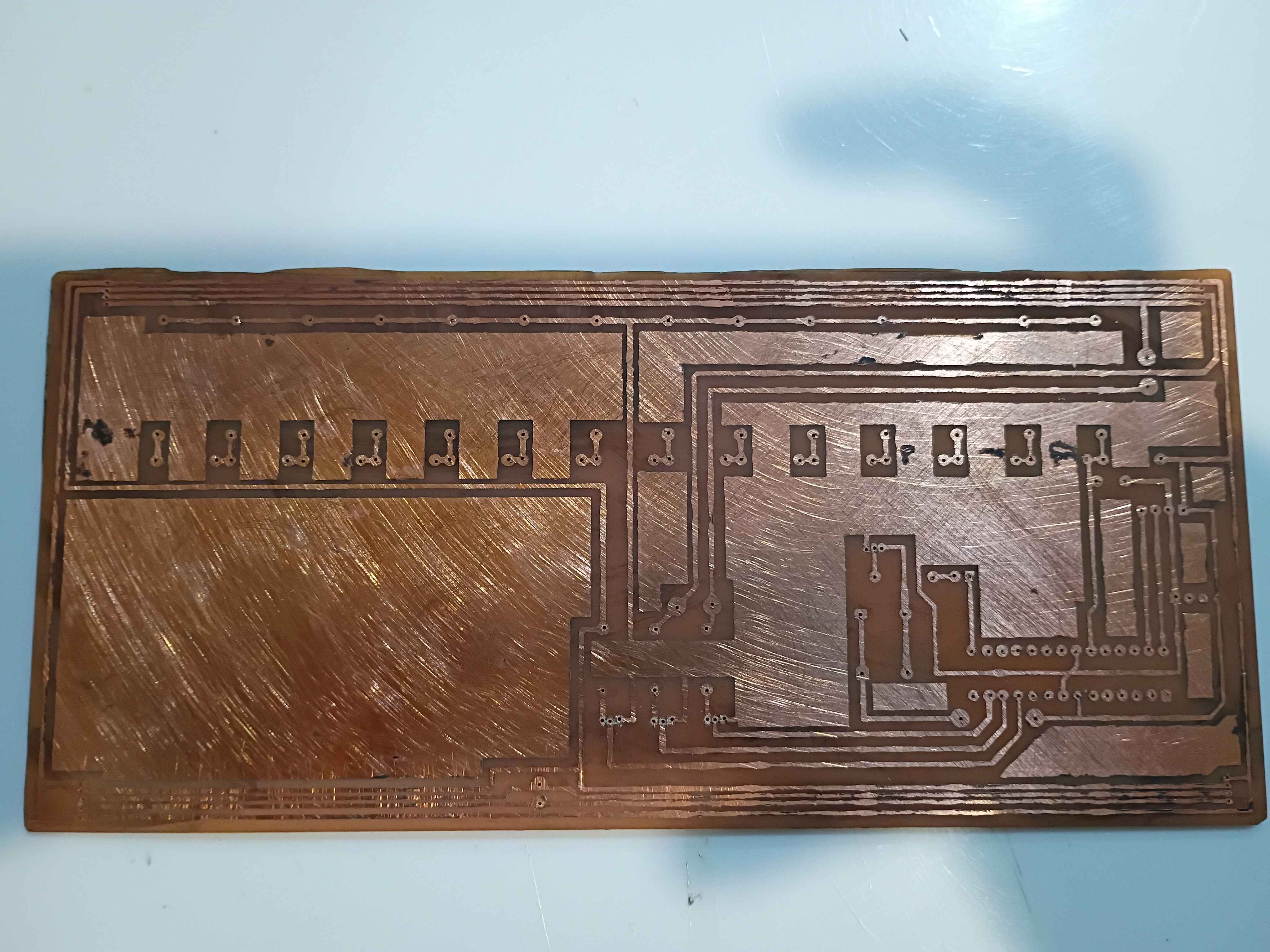
Etched away the copper to reveal the traces. 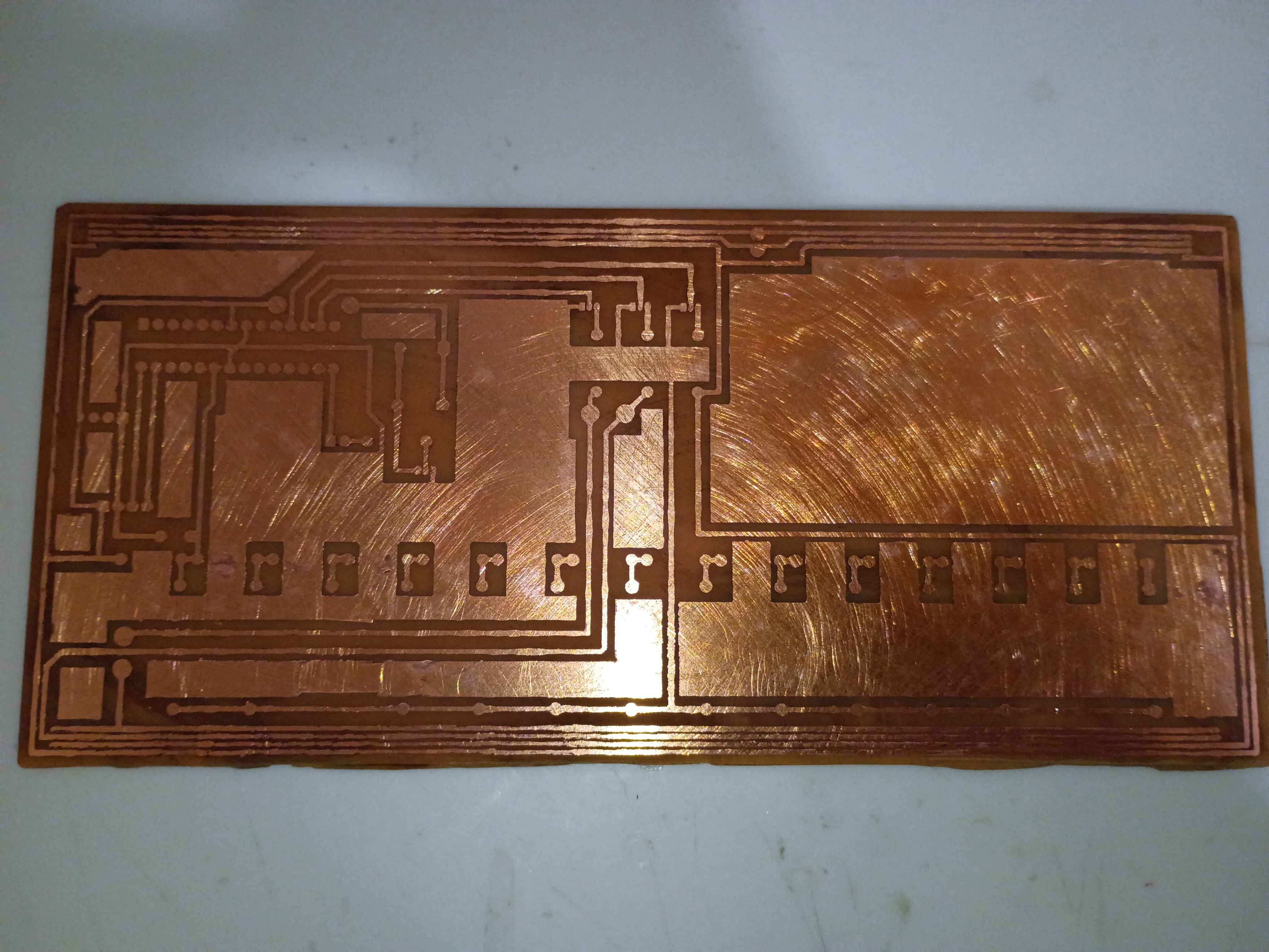
Toner-transferred the copper trace mask on the copper clad board. It actually turned out decently for the size and relative complexity. The edges peeled off a bit, but that always happens for me; I will redraw those areas with Sharpie or masking tape. I also scraped off the lingering bits of paper with a knife. For future reference, I used the iron on max heat, let the board cool briefly before setting it in the water, and let it sit in the water for ~20 minutes before rubbing off most of the paper backing, and 20 more minutes before rubbing off any remaining paper residue. 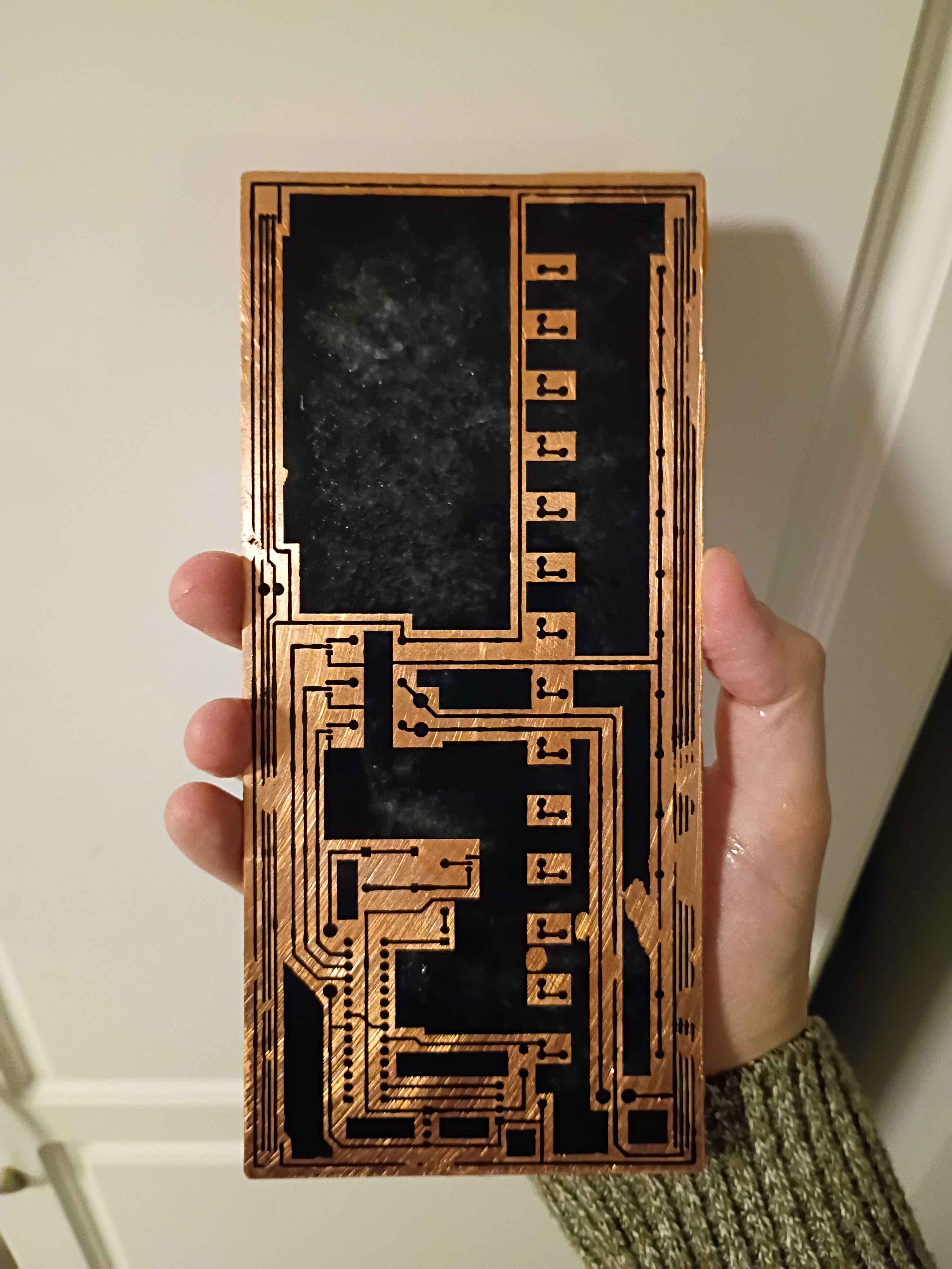
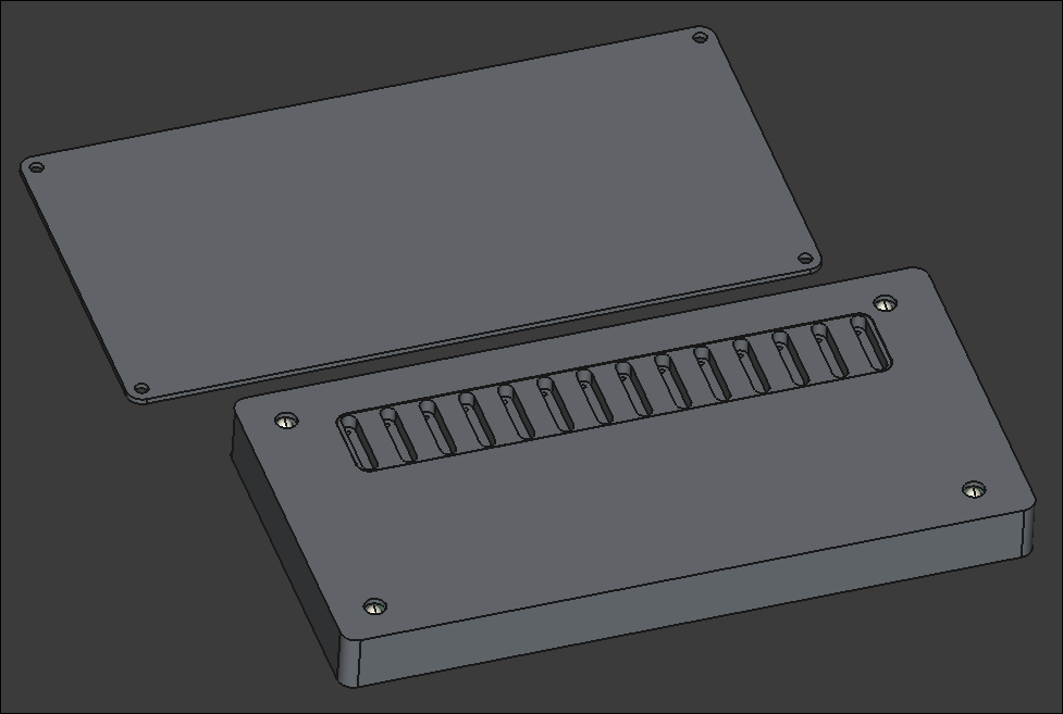
Successfully printed the box assembly from PETG. A little bit of warping on the large flat cover piece, though the screws should hold that in place, and a bit of discoloration streak on the top of the main box component, so I may need to sand/paint or cover with a sticker. Everything fits together well. 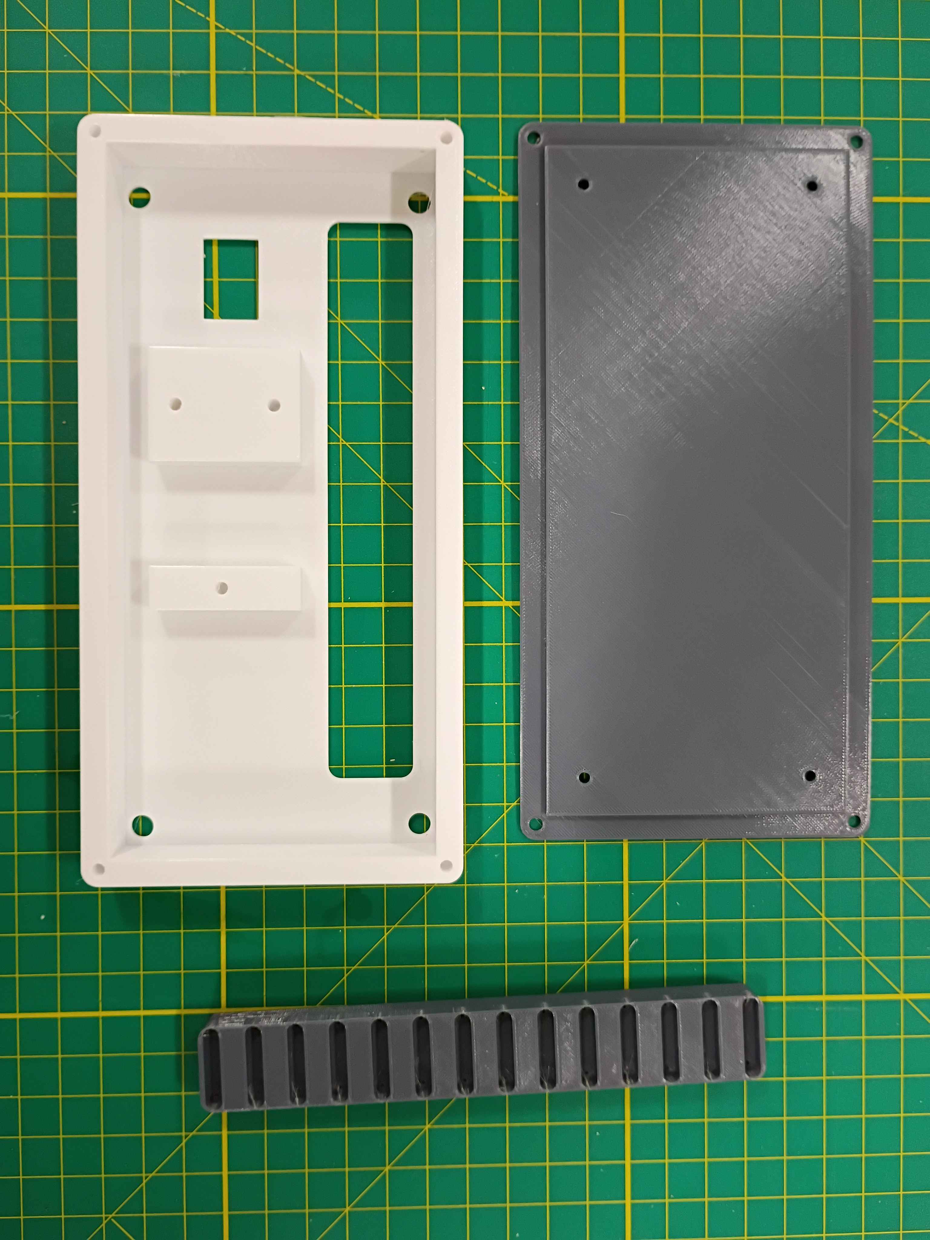
Completed design for a prototype box assembly that should support all the components and the rubber feet I already sourced. Since the part is quite large, it will need to be printed on the machine at work. I will try that tomorrow. I might need to iterate on the main support body at least once to get the depth correct. 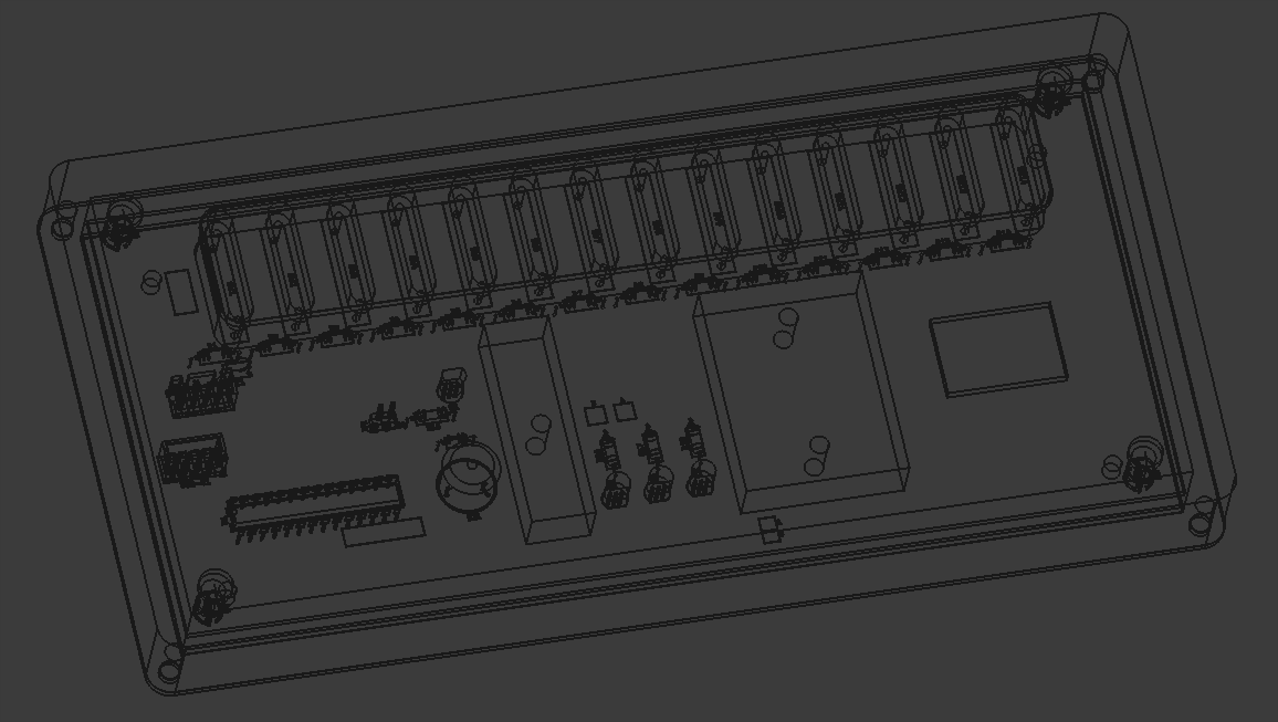
Designed a 3-piece 3D-printed assembly for the project. One component to support the reed switches on the PCB, one box to mount the PCB assembly, and a lid. I still need to add a hole in the top face for the OLED screen. Everything is removably mounted with M3 screws. 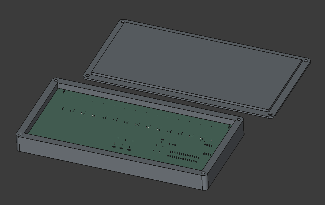
Looking into possibly pivoting away from laser-cut plywood box to a 2-piece 3D-printed box. It would be more robust, reproducible, and suitable for this container, though it will be roughly 230mm wide, which is approaching the maximum for the Prusa MK3S that I will print it on, which may pose problems.
Finalized design of top and front/back of manipulative box. Still considering options for the bottom that are easy to remove for access to repair and replace components.
Continued design of box lid, following the same ridged perimeter profile that worked so well on 03008.
Began the CAD for the box. Imported the PCB STEP file from Kicad to ensure a proper fit.
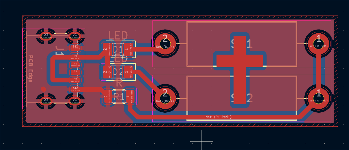
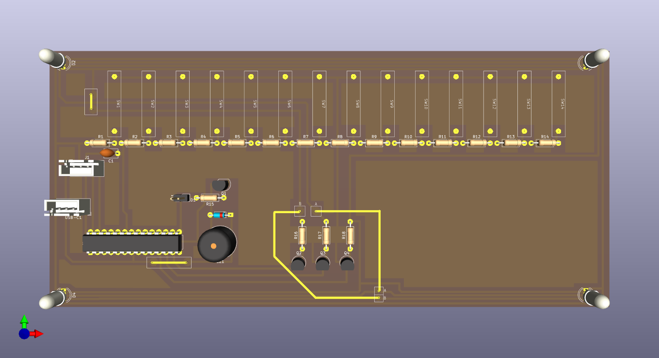
Updated draft schematic and created PCB design for the main control board using the latest PCB-etching lessons learned. This board will be fabricated in-house. See 03010-002 Kicad project. 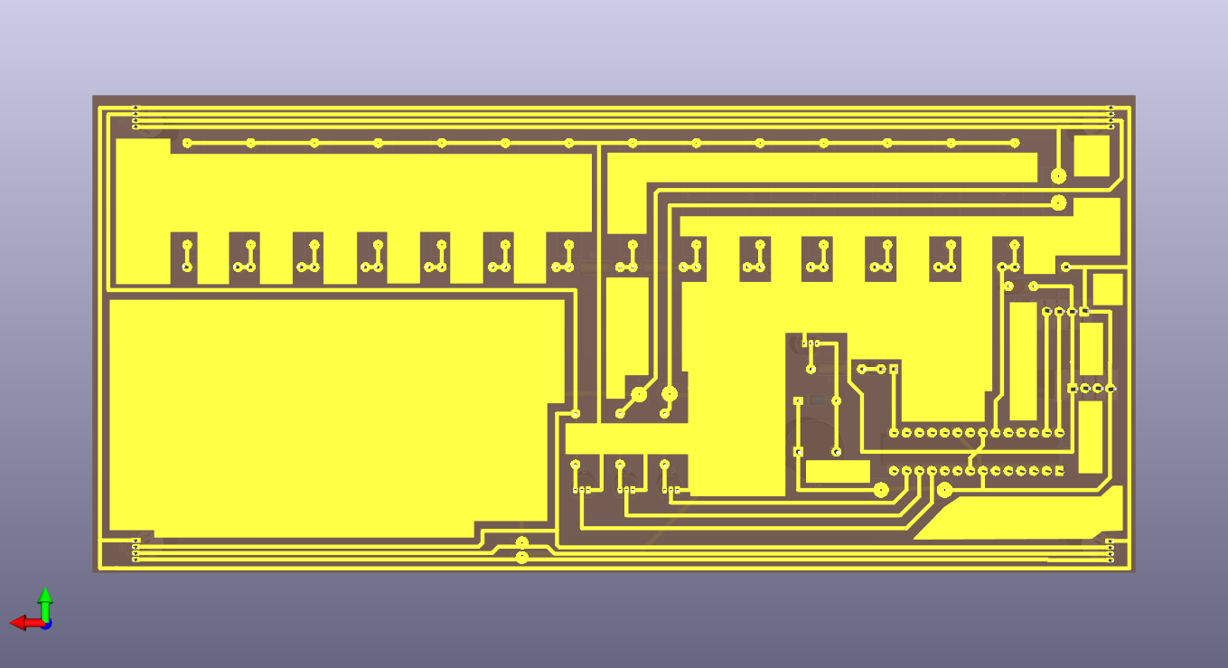
Created draft schematic for the main control board. See 03010-002 Kicad project. 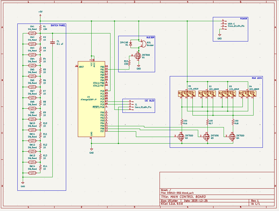
Created SVG for laser cutting & engraving simplified ruler. See project CAD directory. 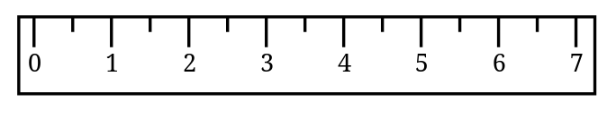
After brainstorming follow-on math manipulatives with the client, we are launching a prototype effort for a manipulative involving ruler measurements. As was learned on xMM1, moving parts and a tactile input device make the manipulative very engaging for the children. This manipulative will consist of a box with an exposed sliding piece of plastic that the children will need to measure. The plastic slide will be connected to a rack and pinion so it can be driven by a servo to expose different lengths of plastic to be measured. The children will need to place a ruler against the box, and to make sure they line up the ruler correctly with the start of the plastic slide, there will be a reed switch that detects that and shows a green status LED. When the measurement is made, the child will be able to select the value (in half-inch increments) using a pegboard, by putting a peg with a magnet into the corresponding marked circular slot. The different values can be connected to a series of resistors to be able to detect the voltage value with a single ADC pin, versus having to waste a lot of GPIO pins. If the rack and pinion approach does not work due to space limitations, a servo-controlled paper scroll can be used instead.