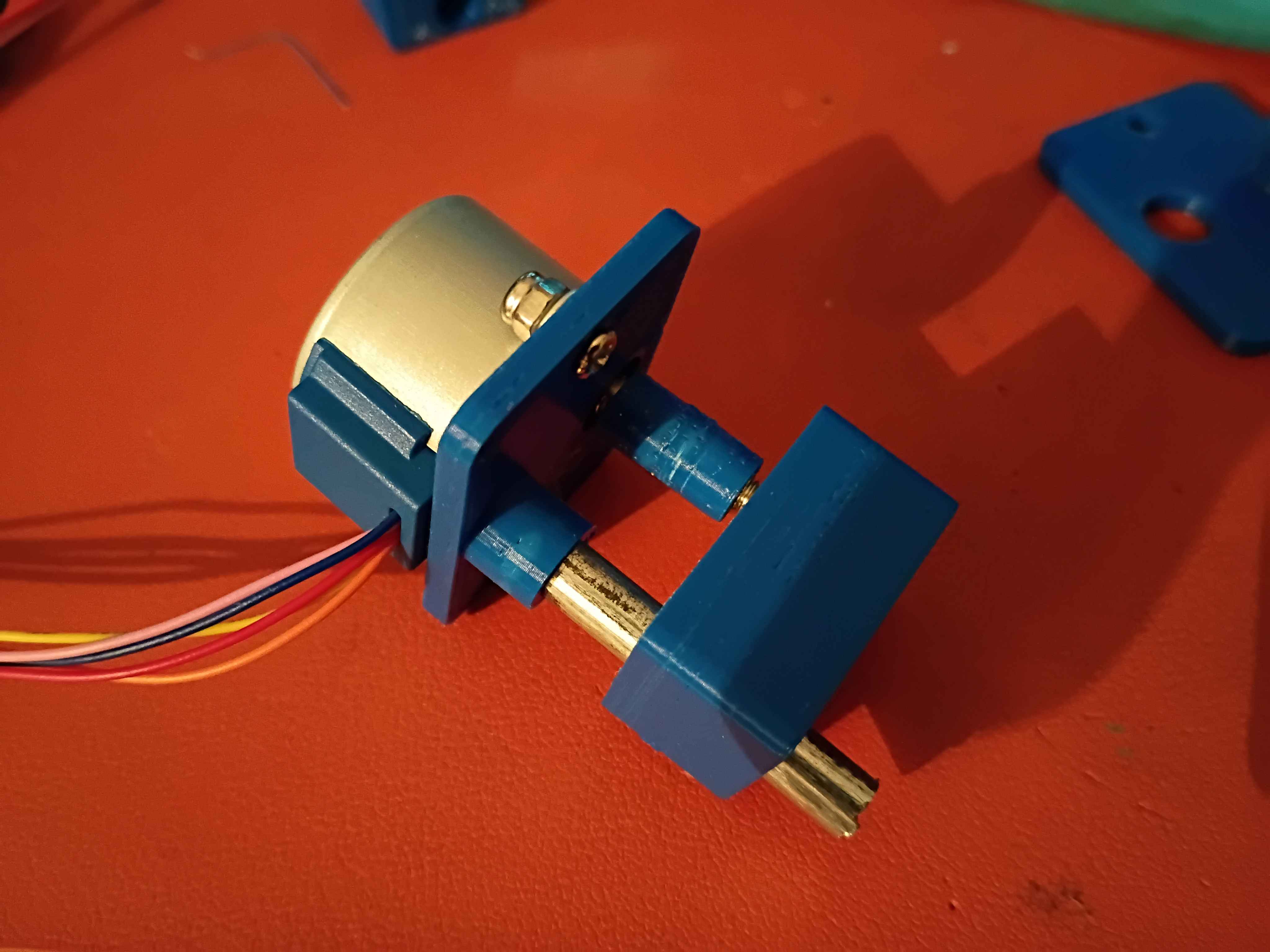
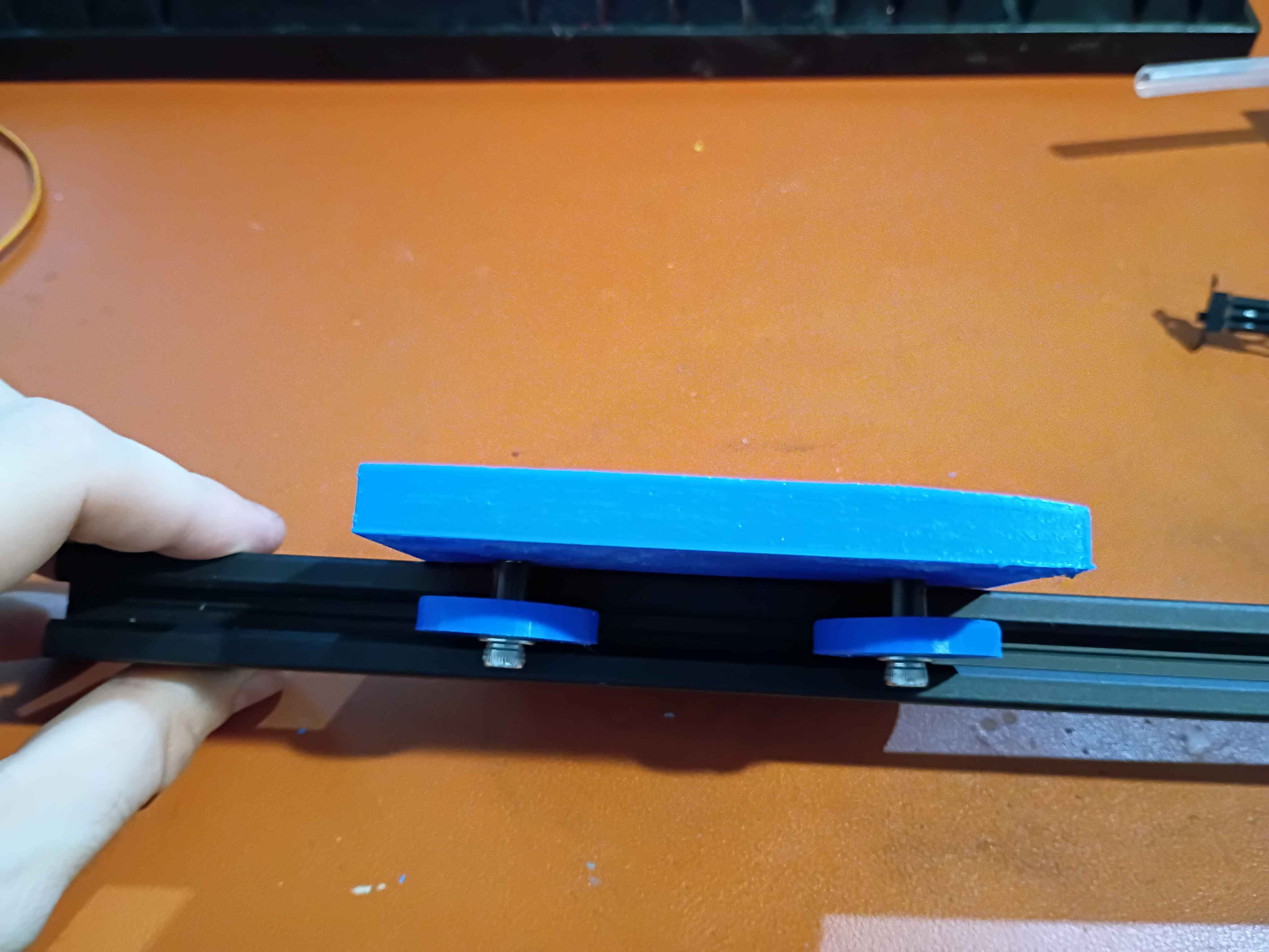
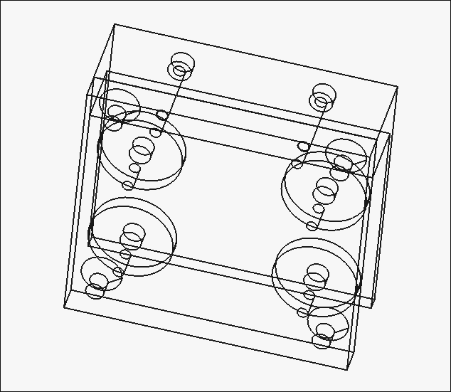
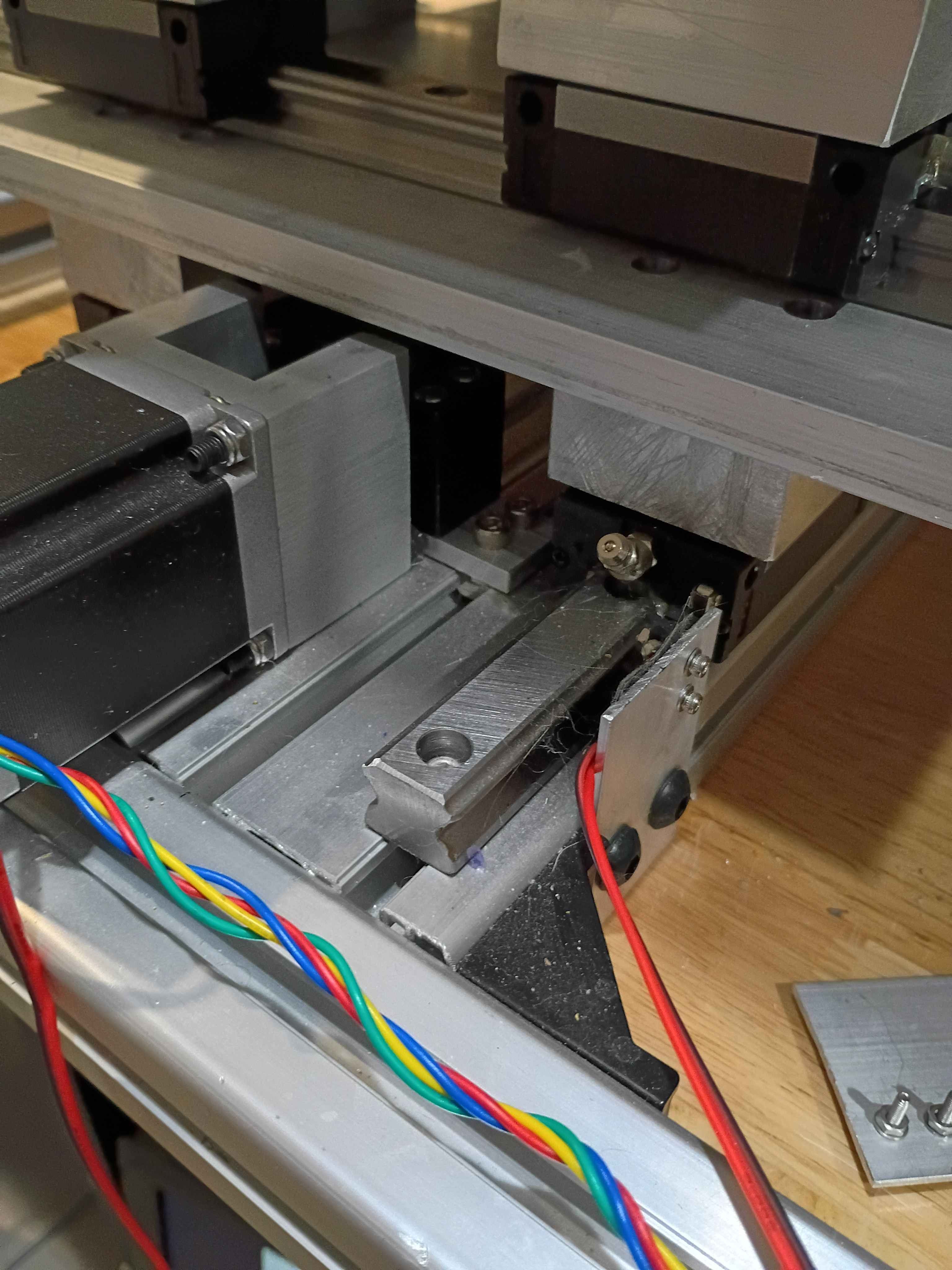
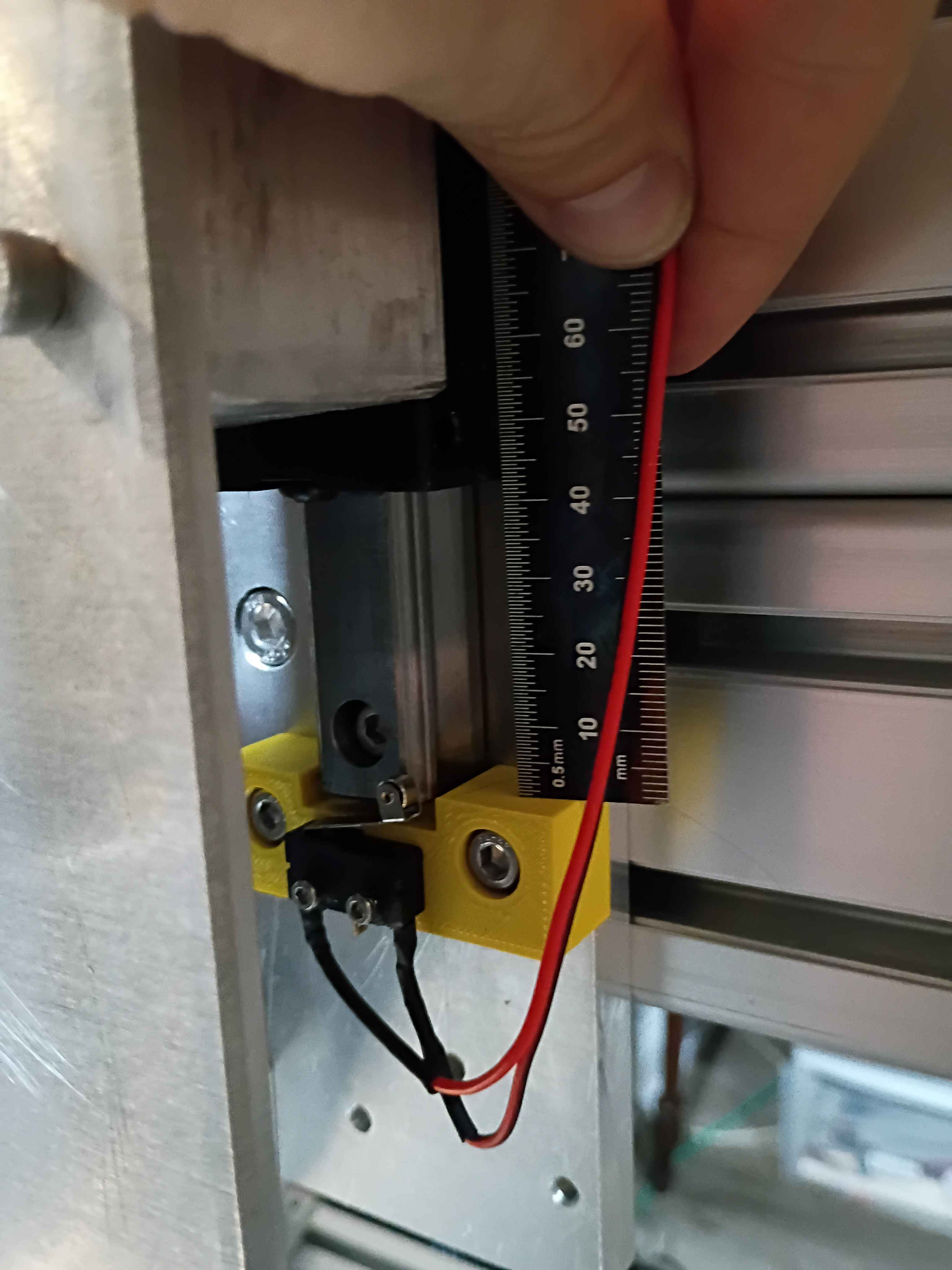
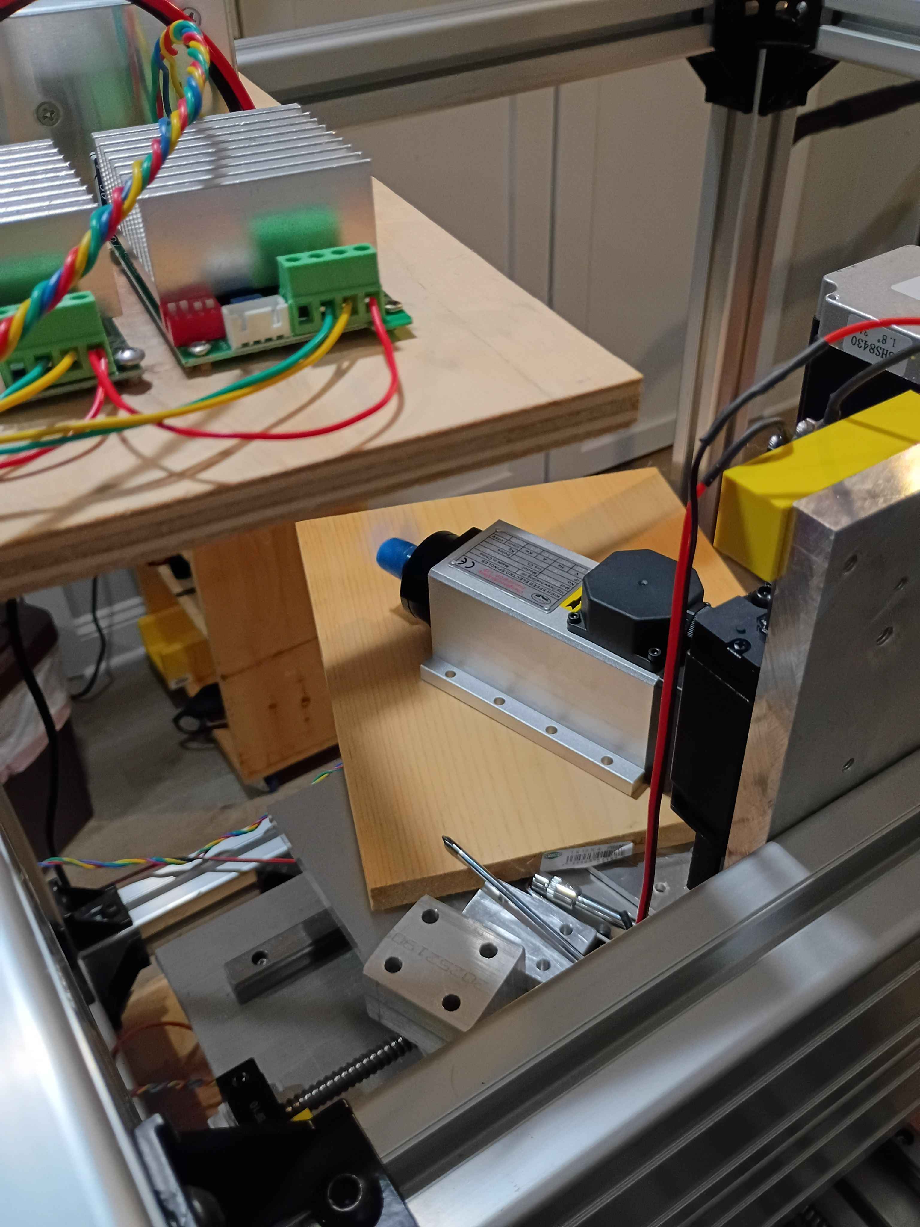
Designed and printed 2 iterations of this short stroke linear actuator that uses an M4 screw, a T slot nut and a stepper motor, but the stroke on this is currently only 2mm, which is not enough to pinch the silicone tubing, and it needs some chassis that contains the tubing as well.
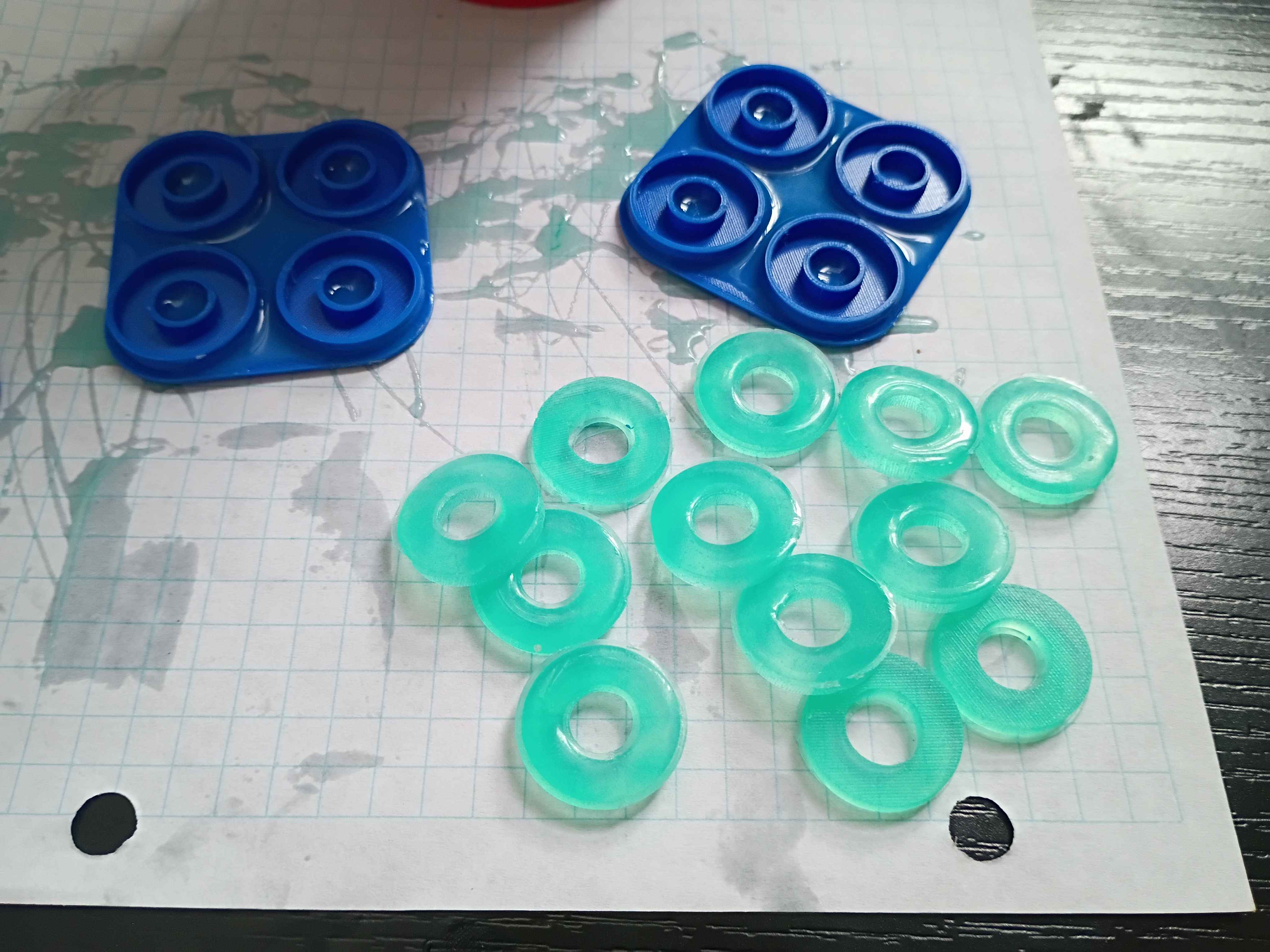
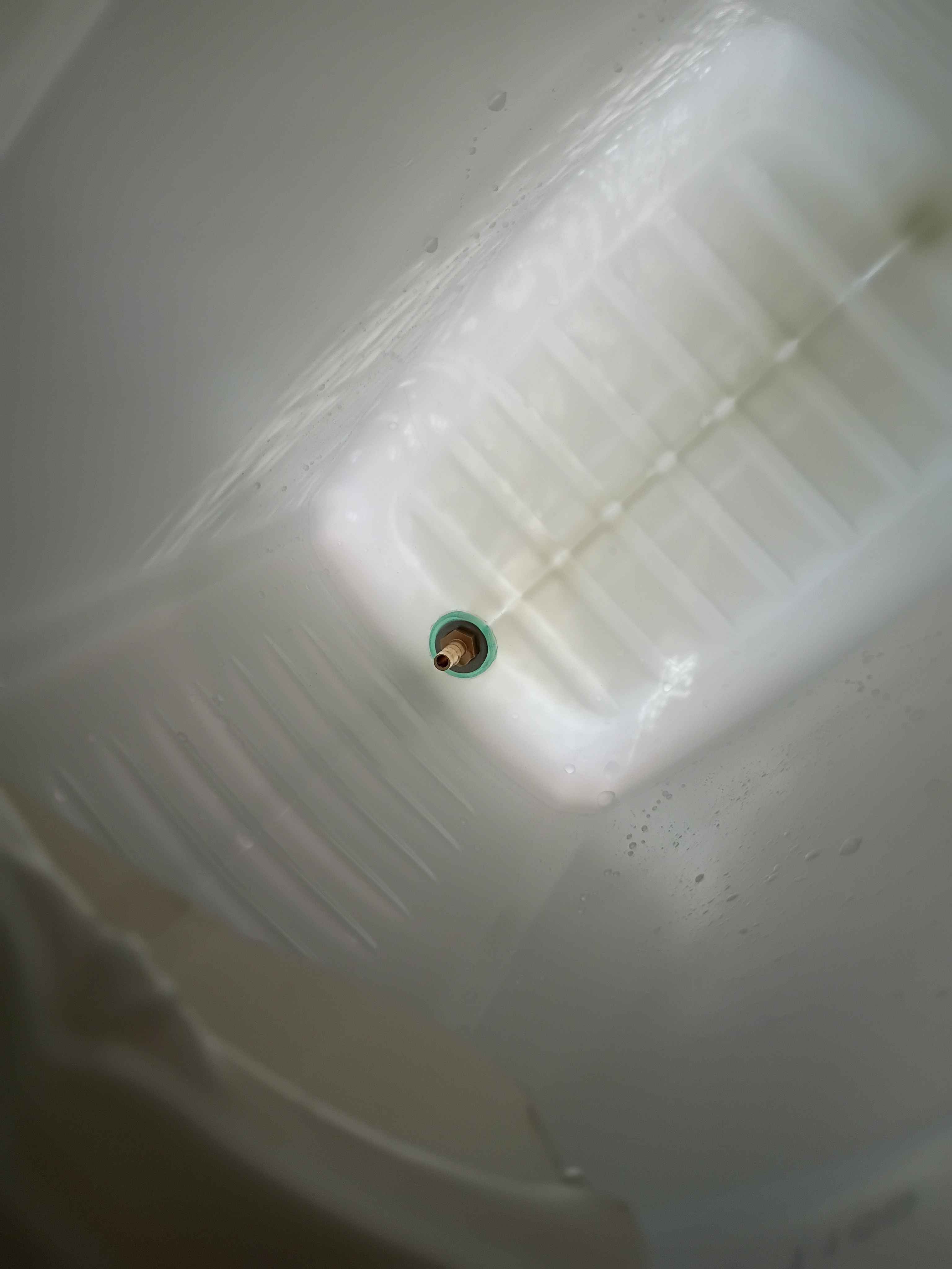
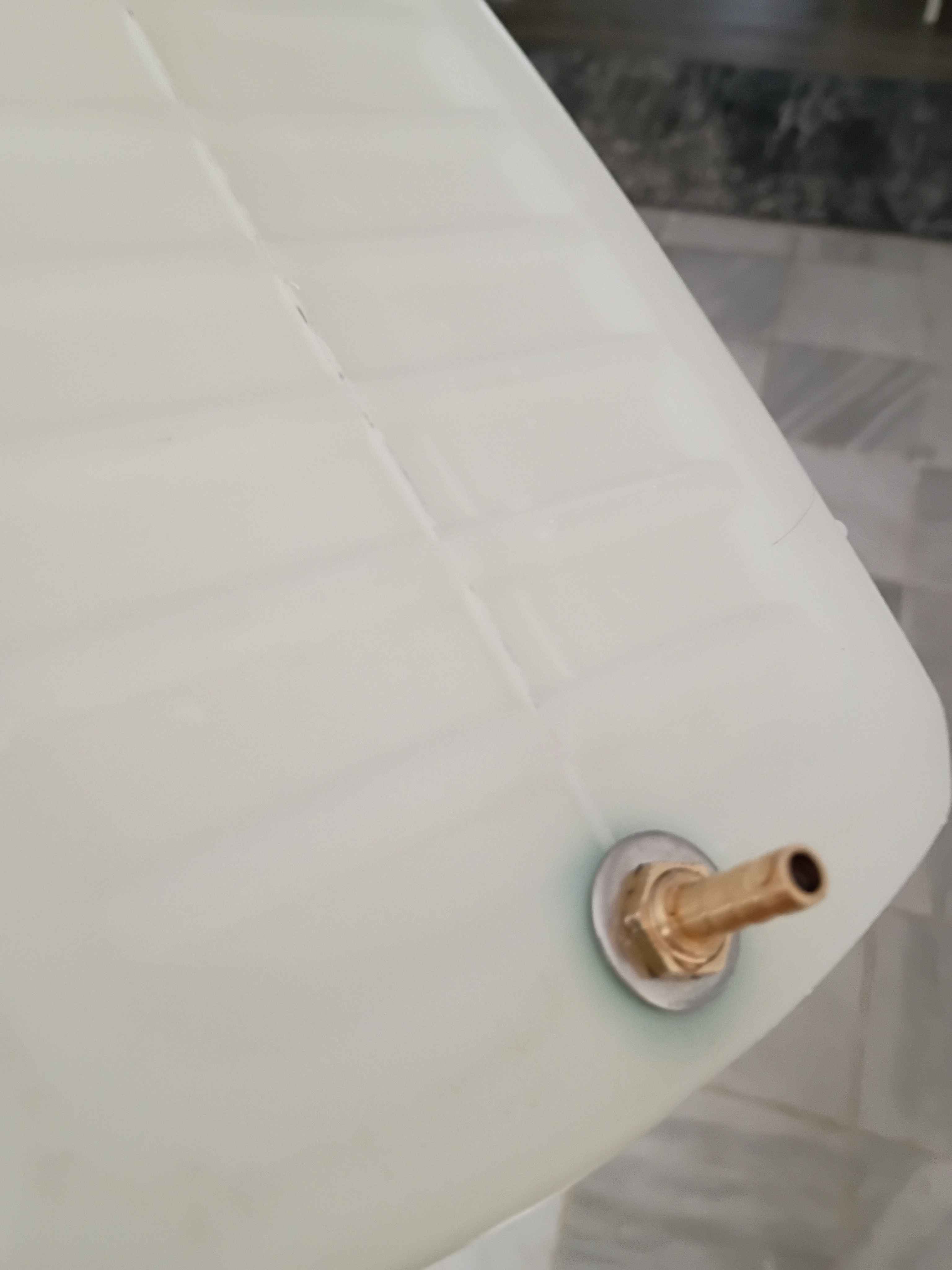
Printed molds and casted silicone gaskets for the water reservoir nipples. 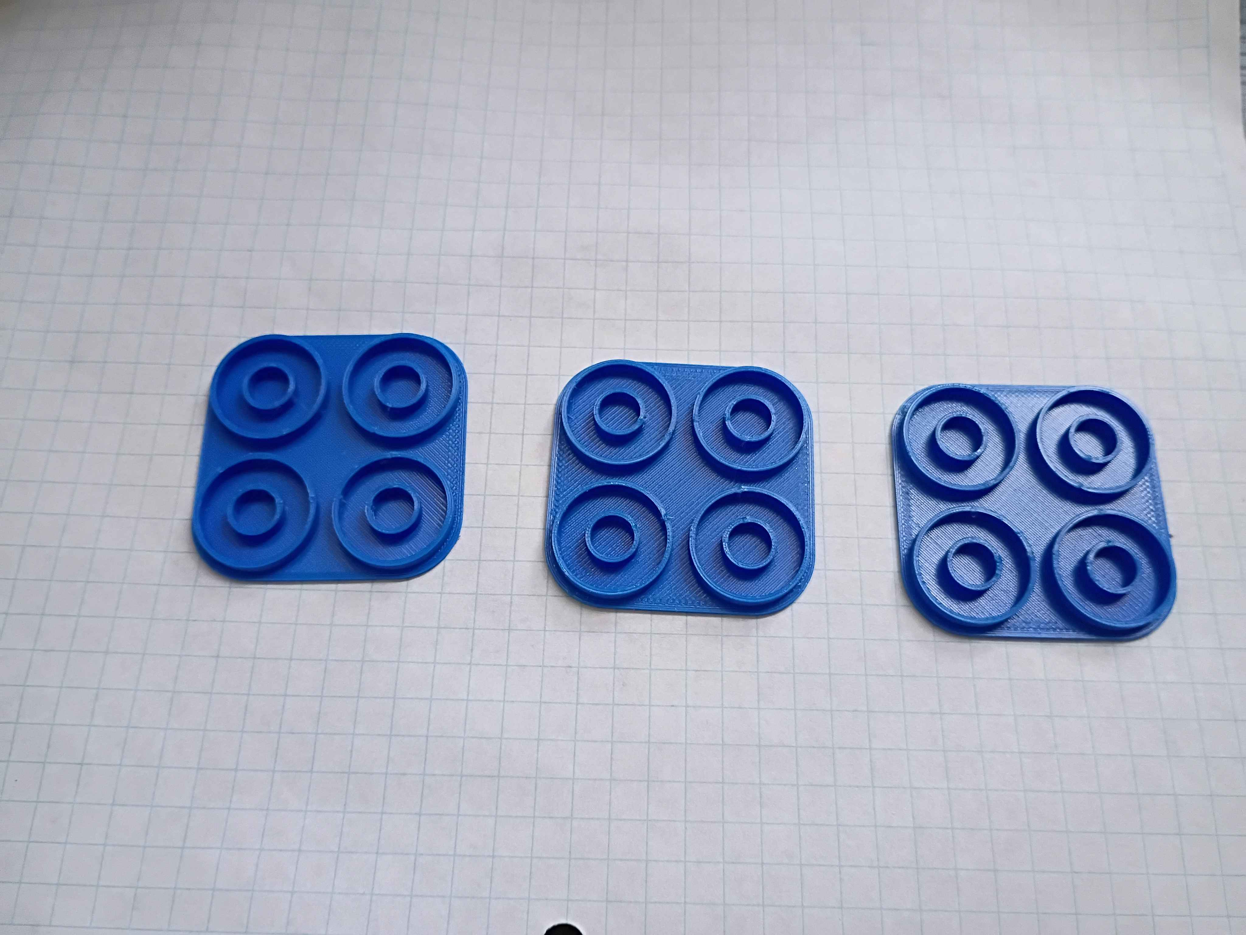
Wrote test code to sweep servo motion. See video.
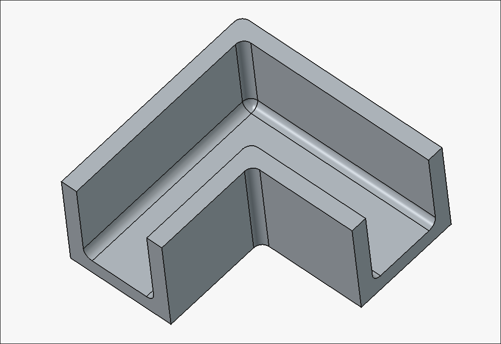
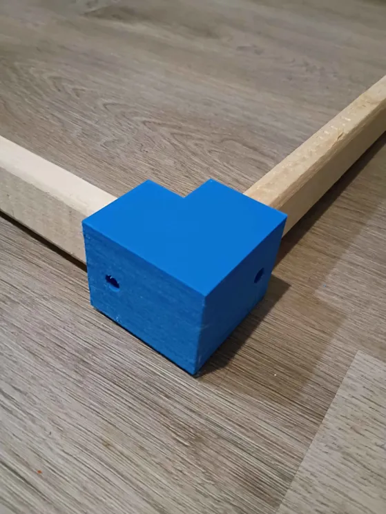
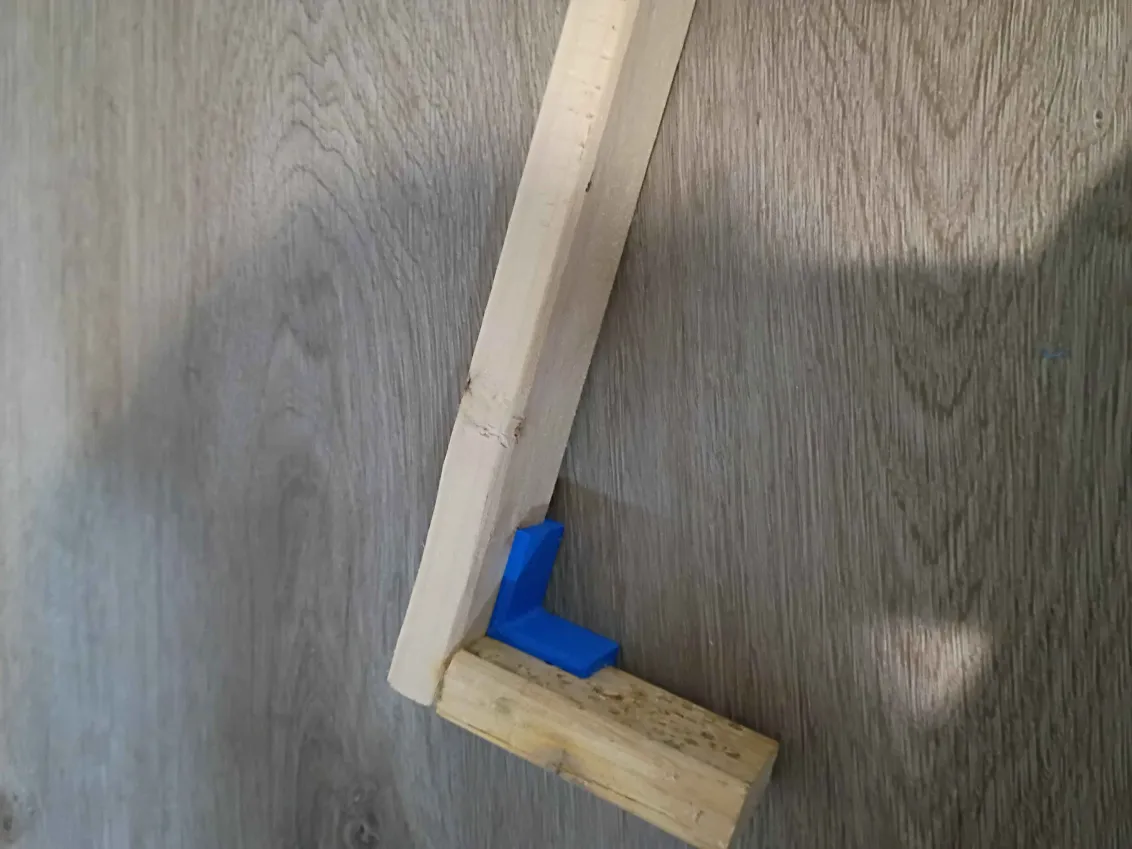
Designed and printed 2 joints for furring strips. These have several planned uses. 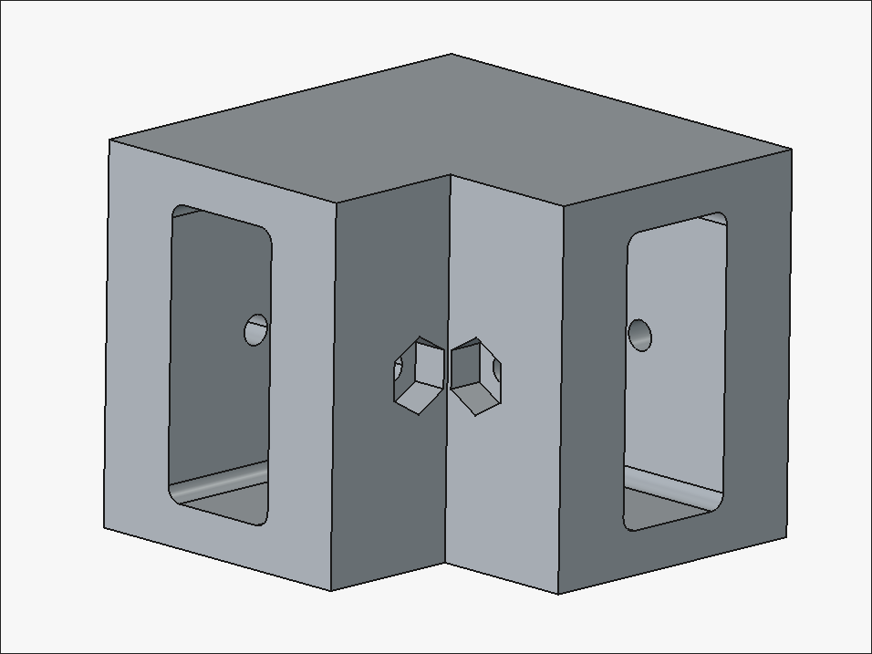
Designed a dock for an Apple Watch charging dongle. It mounts to the 1-inch thick headboard of a bedframe. 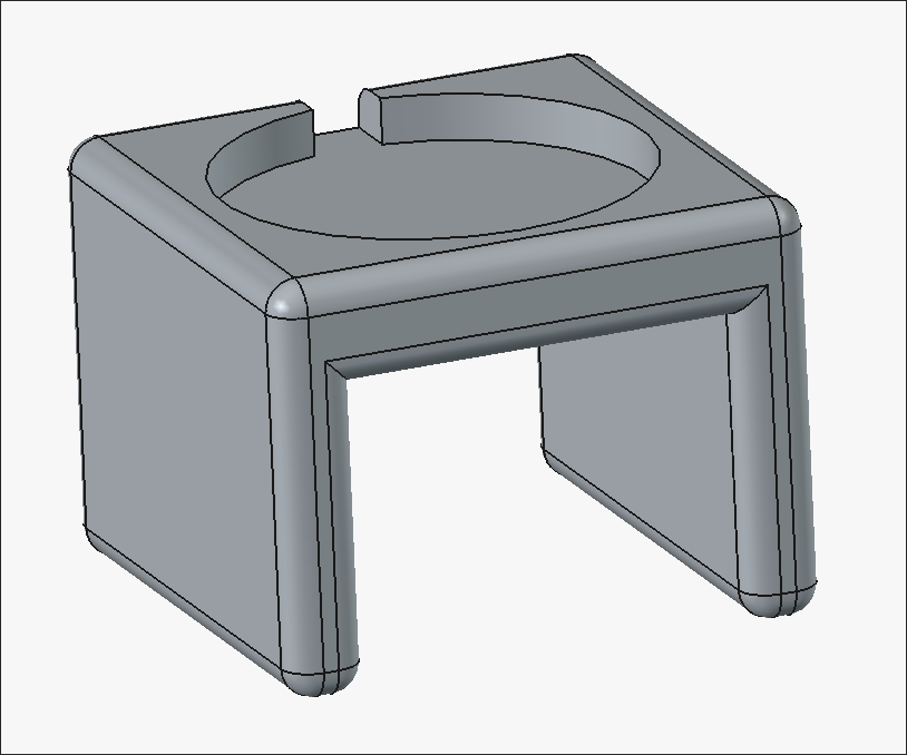
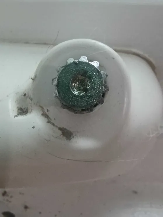
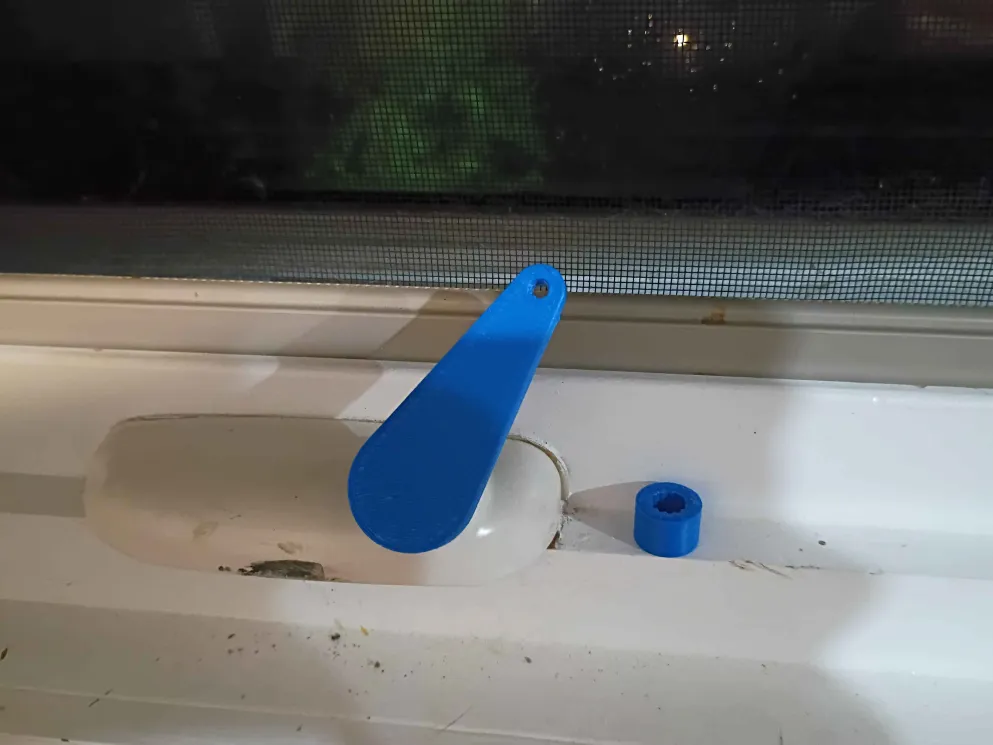
Designed and printed a window crank. It took 2 iterations of the adapter to get it correct. This sets the stage for an automated window control unit. 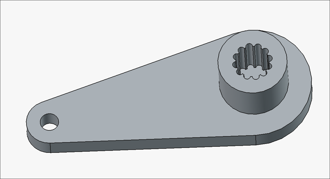
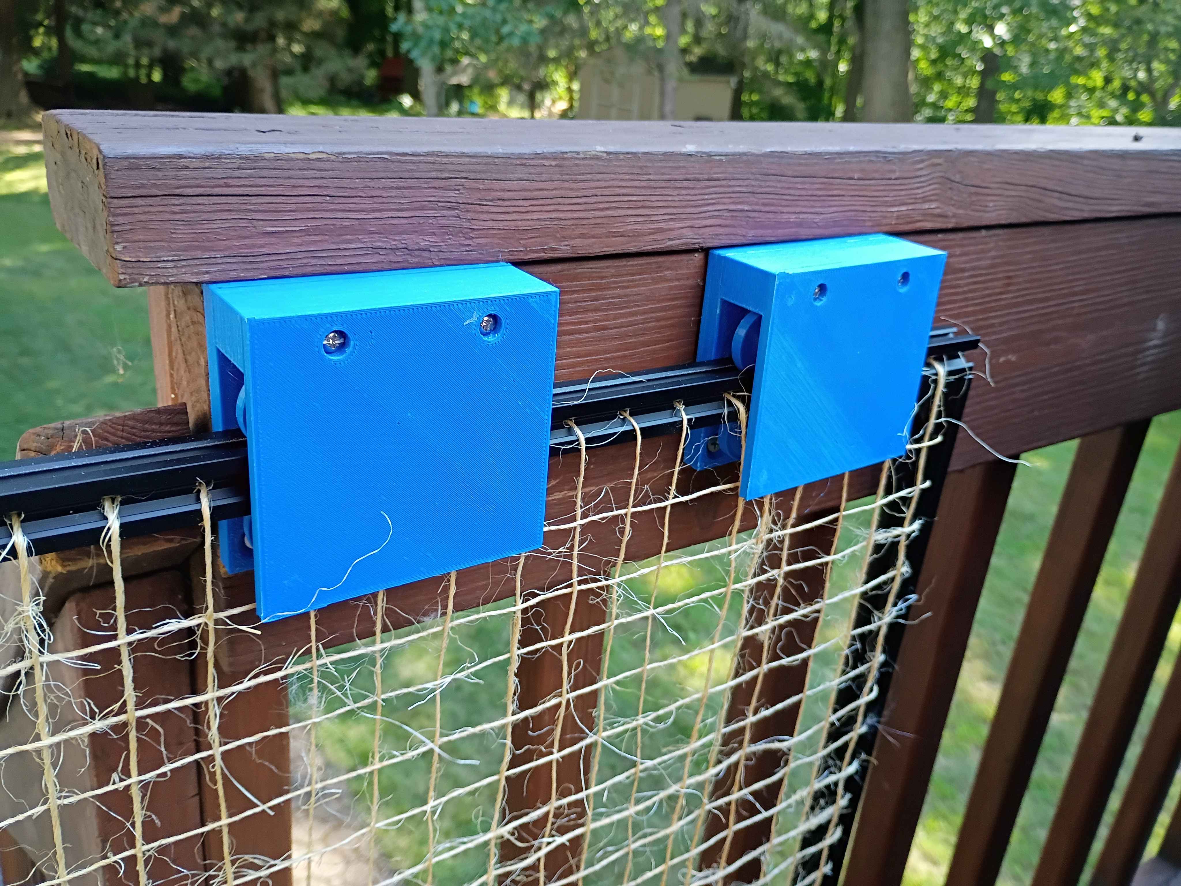
Installed handle. Overall system works very well and is quite smooth to operate. The lightweight nature of the gate is decent but the twine is not especially sturdy, though it would be enough to keep the cat in, which is the intended purpose. The fact that the bottom and cantilevered ends are wholly unsupported does make it seem somewhat fragile. Maybe something could be done to lock the gate in the closed position.
Installed new bracket assembly to raise the entire gate 4mm, which was enough for ground clearance. Also designed and printed this little knob handle that I will install tomorrow. 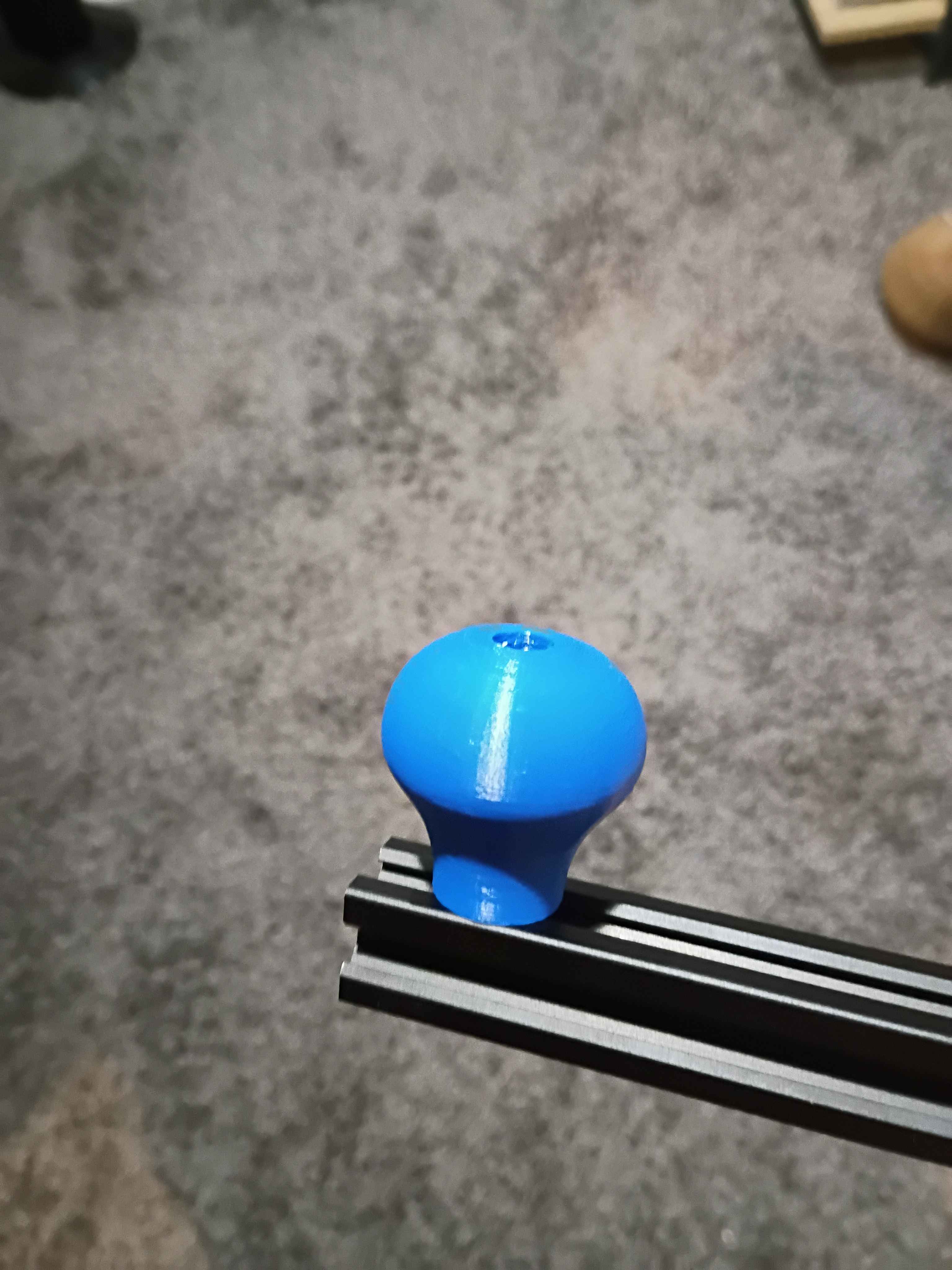
Weaved sisal twine into frame (took a long time) and installed it in on the client's deck. It rubs slightly against the floorboard so I designed and am reprinting the mounting brackets to raise it a few millimeters. In the limit I want to make a handle, some locking feature on the wall end, some soft end cap on the exposed extrusion edge, possibly convert away from 3D-printed ASA to metal components, and make the actual gate a bit more sturdy by running some reinforcement stringers (maybe steel cable). 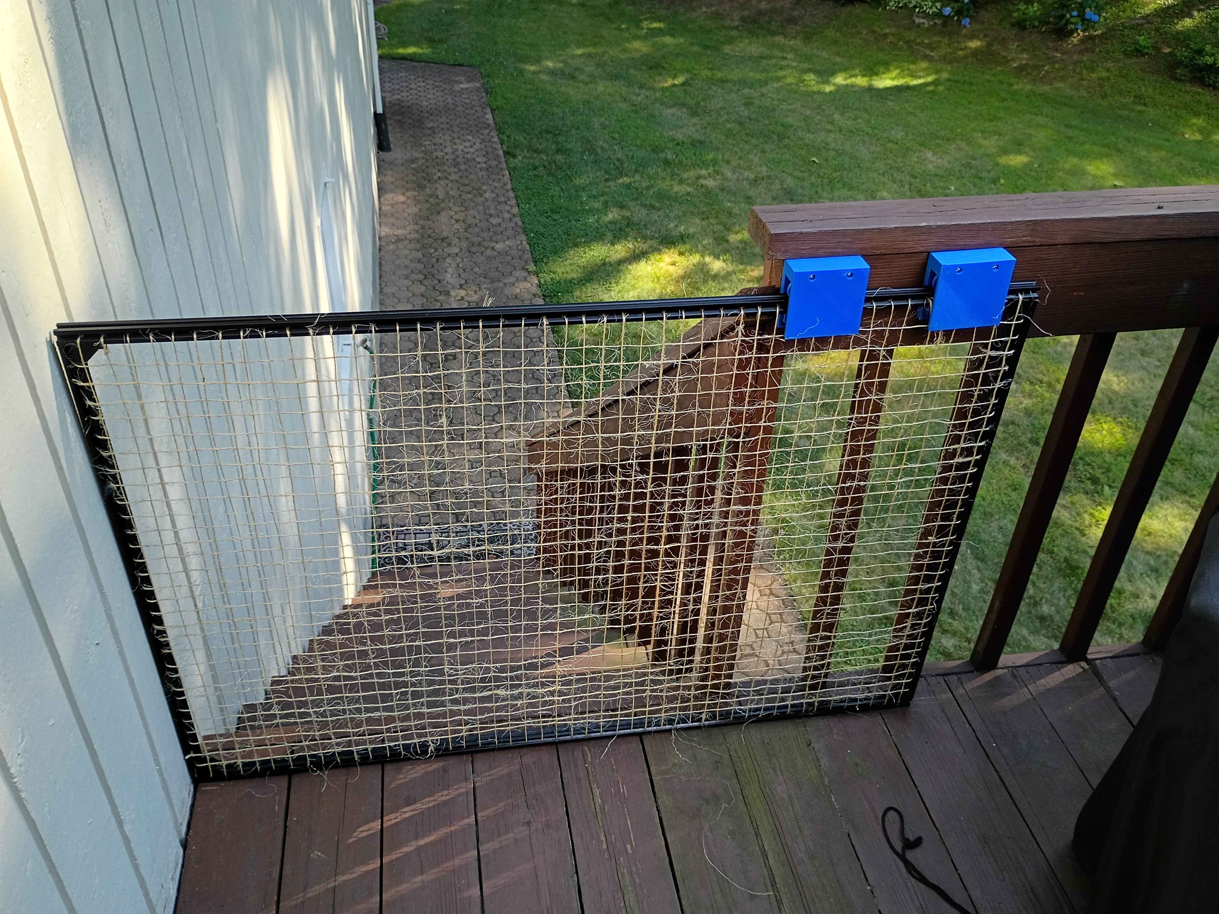
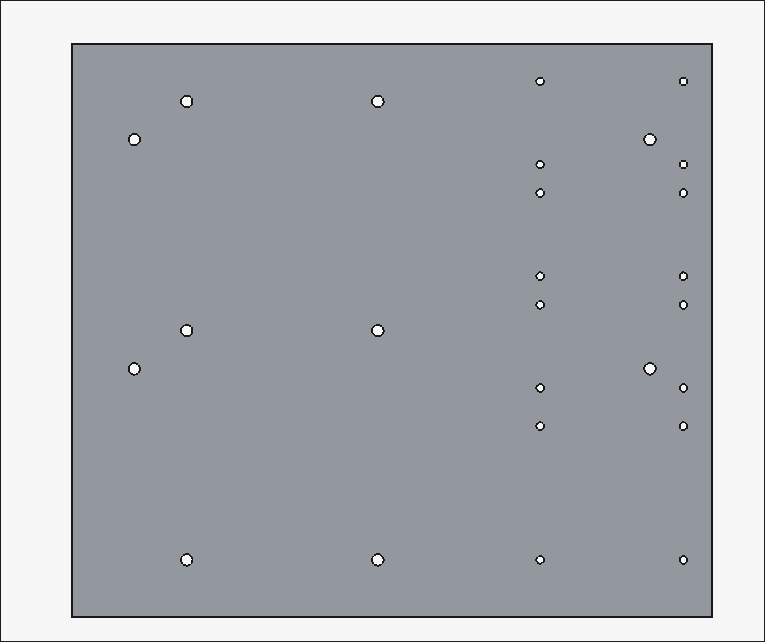
Cut 2020 aluminum extrusion for the gate. Drilled holes every inch along each bar for eventual threading of wire. Assembled the entire frame along with the carriage assemblies. 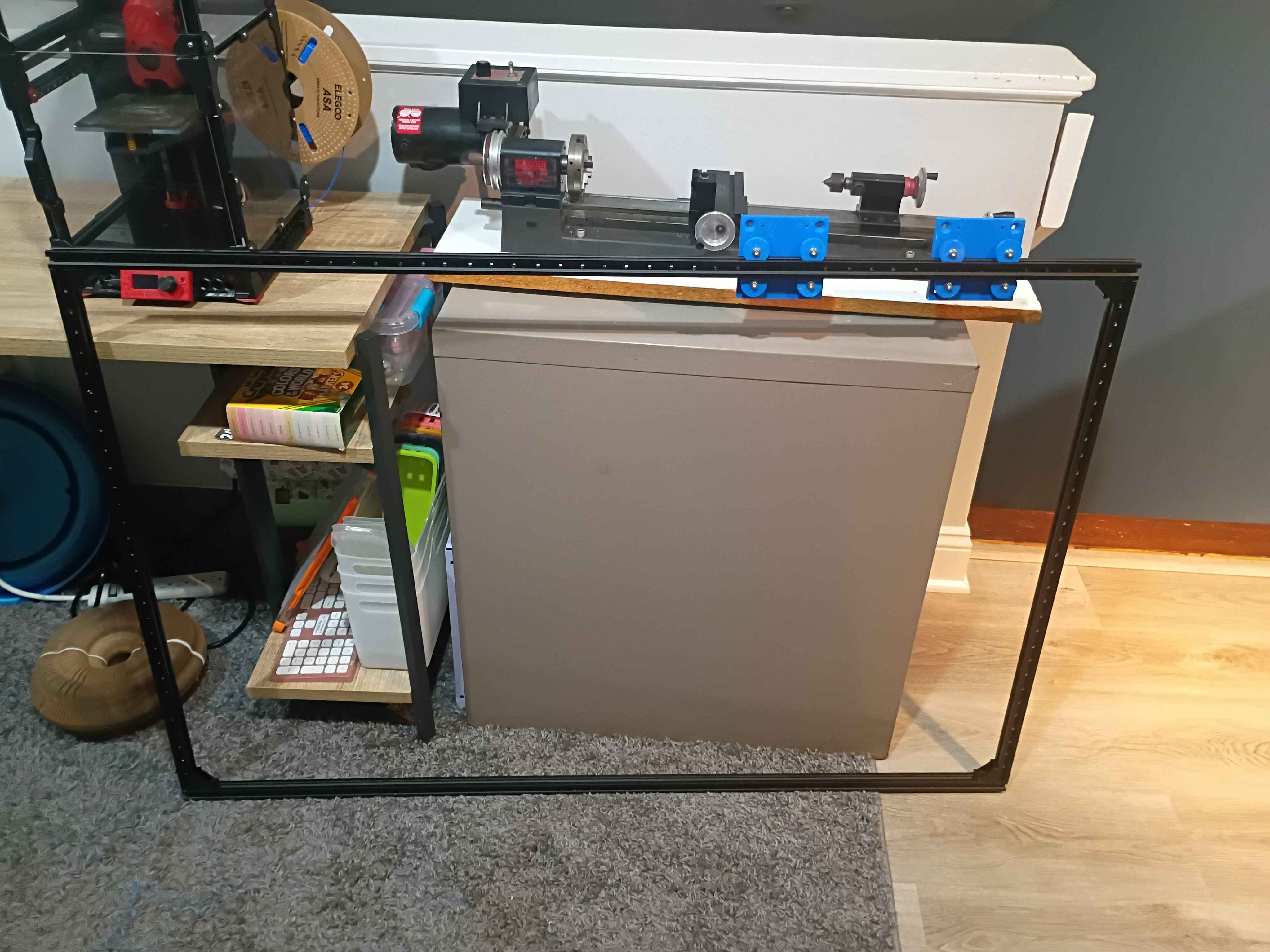
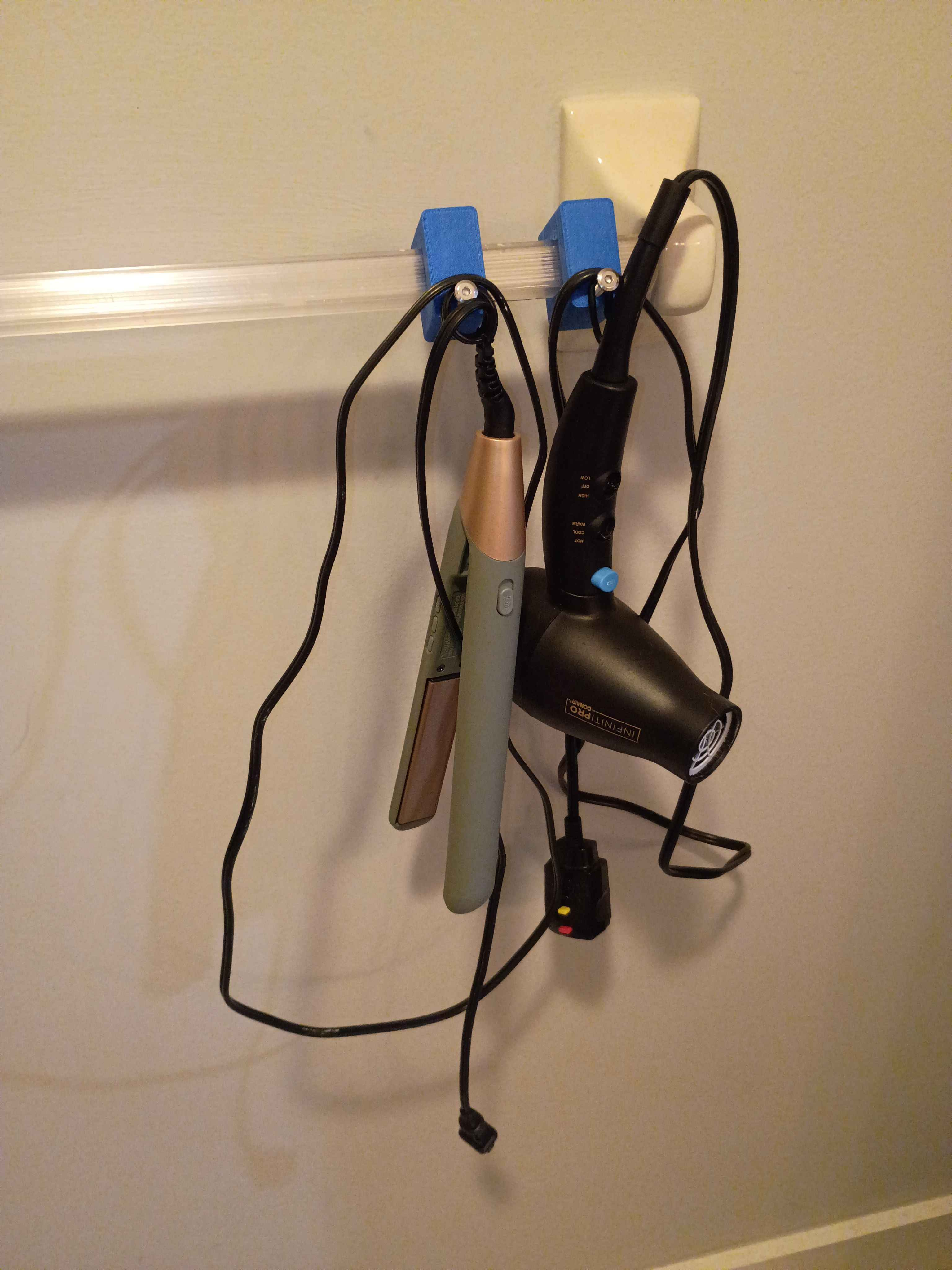
Designed and printed some bathroom organization hooks. 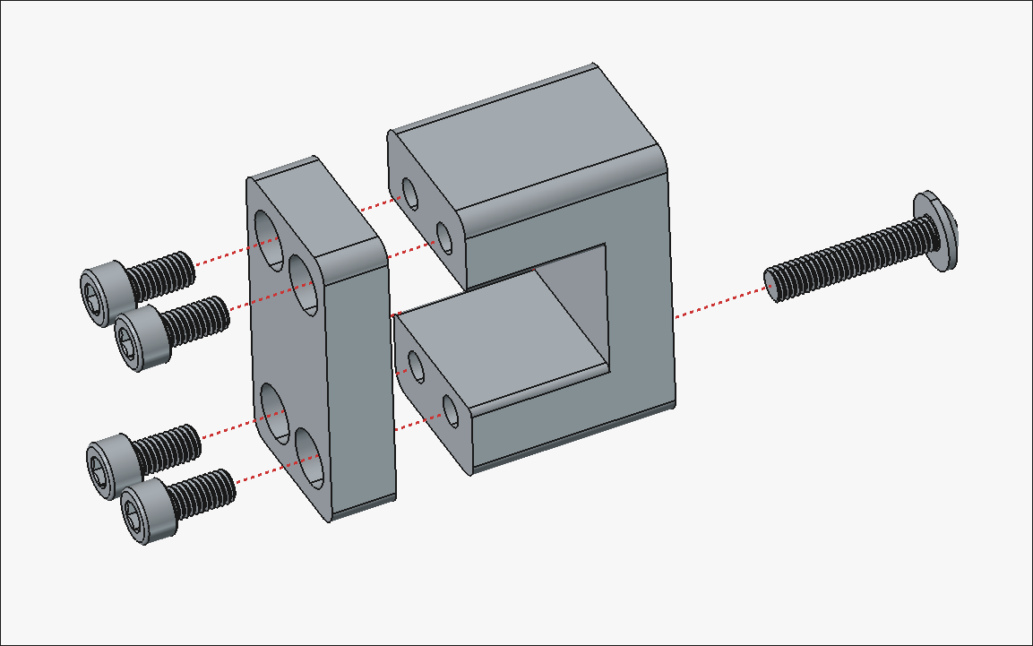
Printed another set of the components to hold the gate at 2 points.
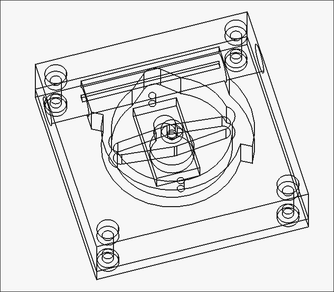
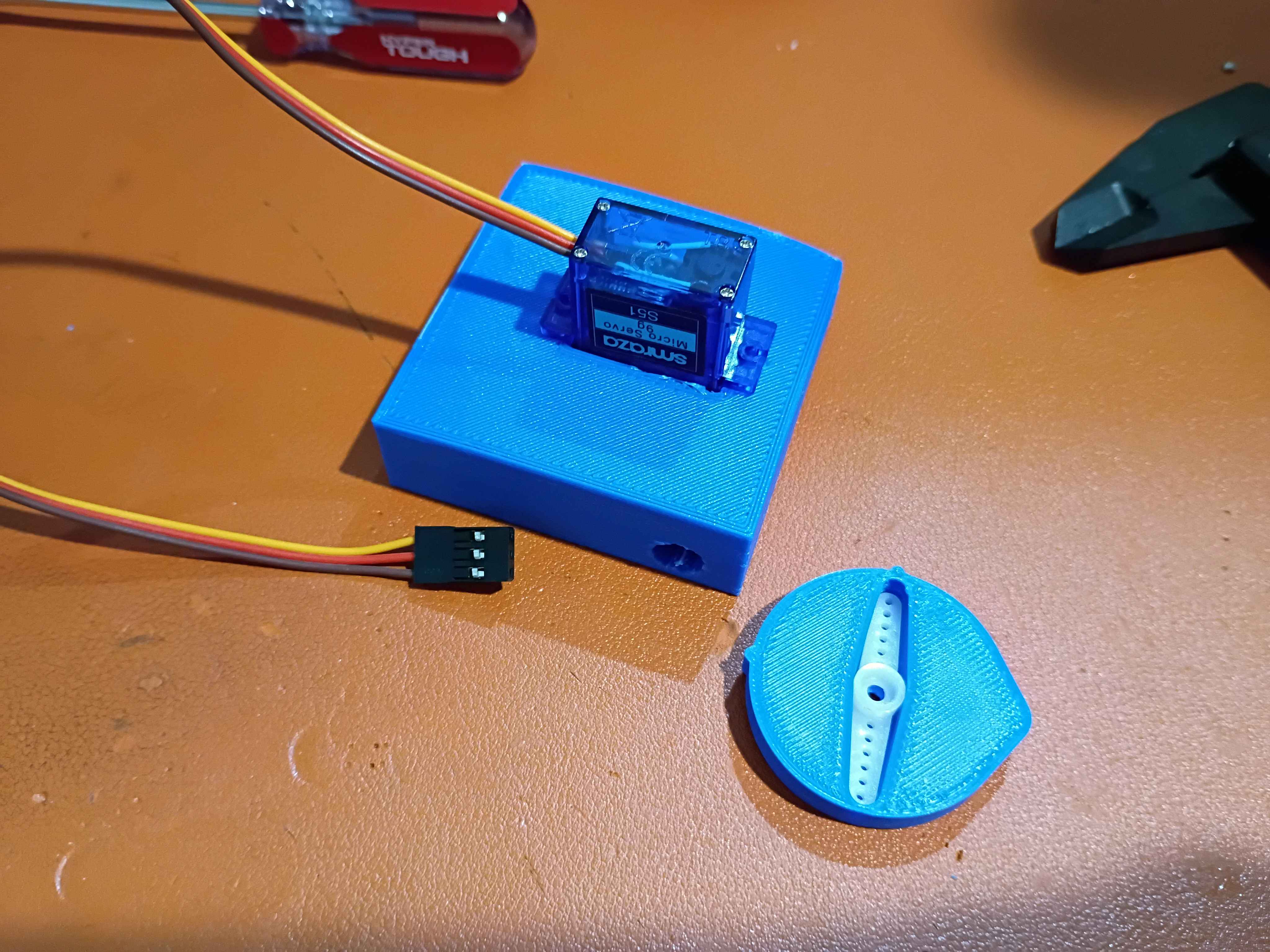
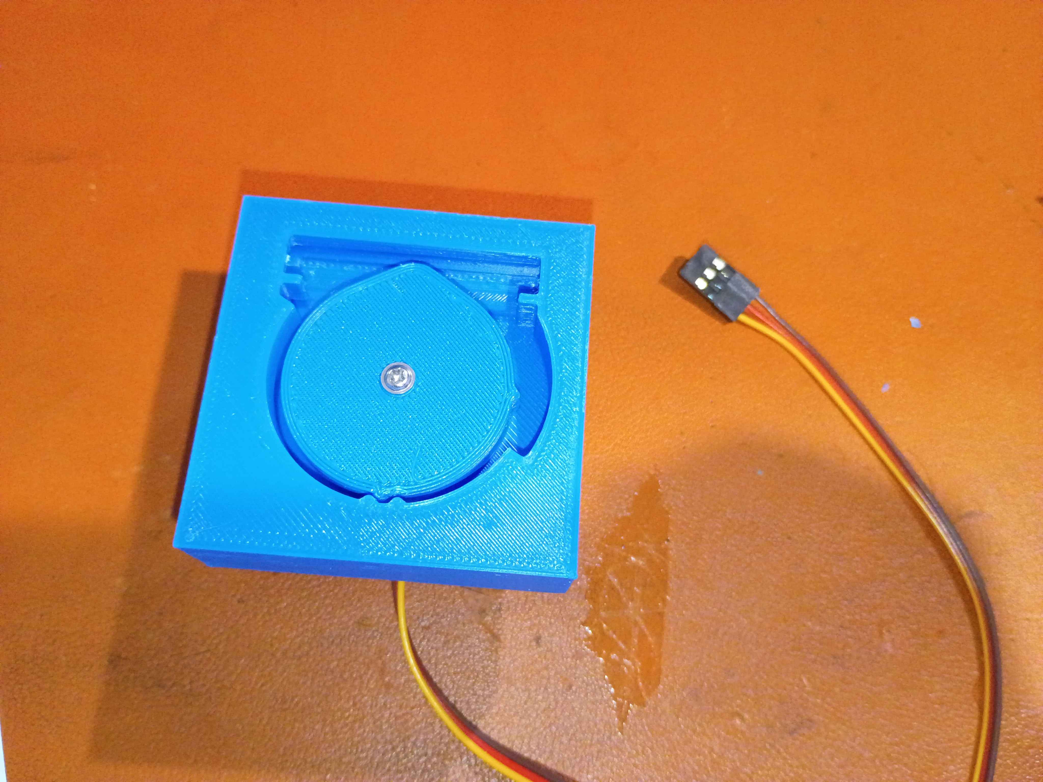
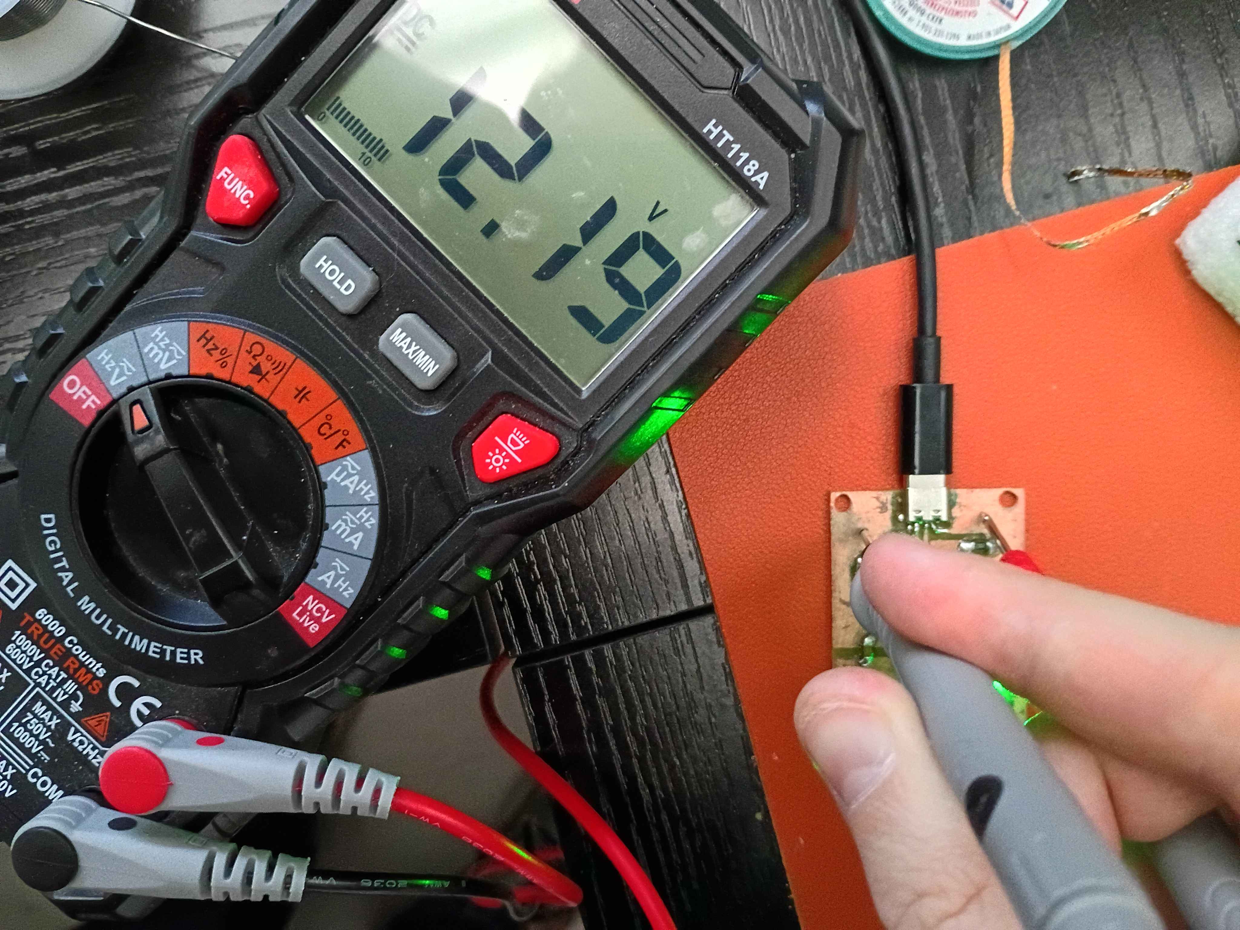
Mark 2 of the pinch valve uses the entire 180 rotation of the cheap servo but will hopefully have enough torque. I could shrink the length of the larger component slightly. It's unclear to me how this would work in a water line since this in effect would need to create 2 bends to keep the line running the same direction, but maybe if there is enough slack it would be OK either way. Need to hook this up to a different controller to get the full rotation, since the one I soldered previously had resistors selected for 45deg. 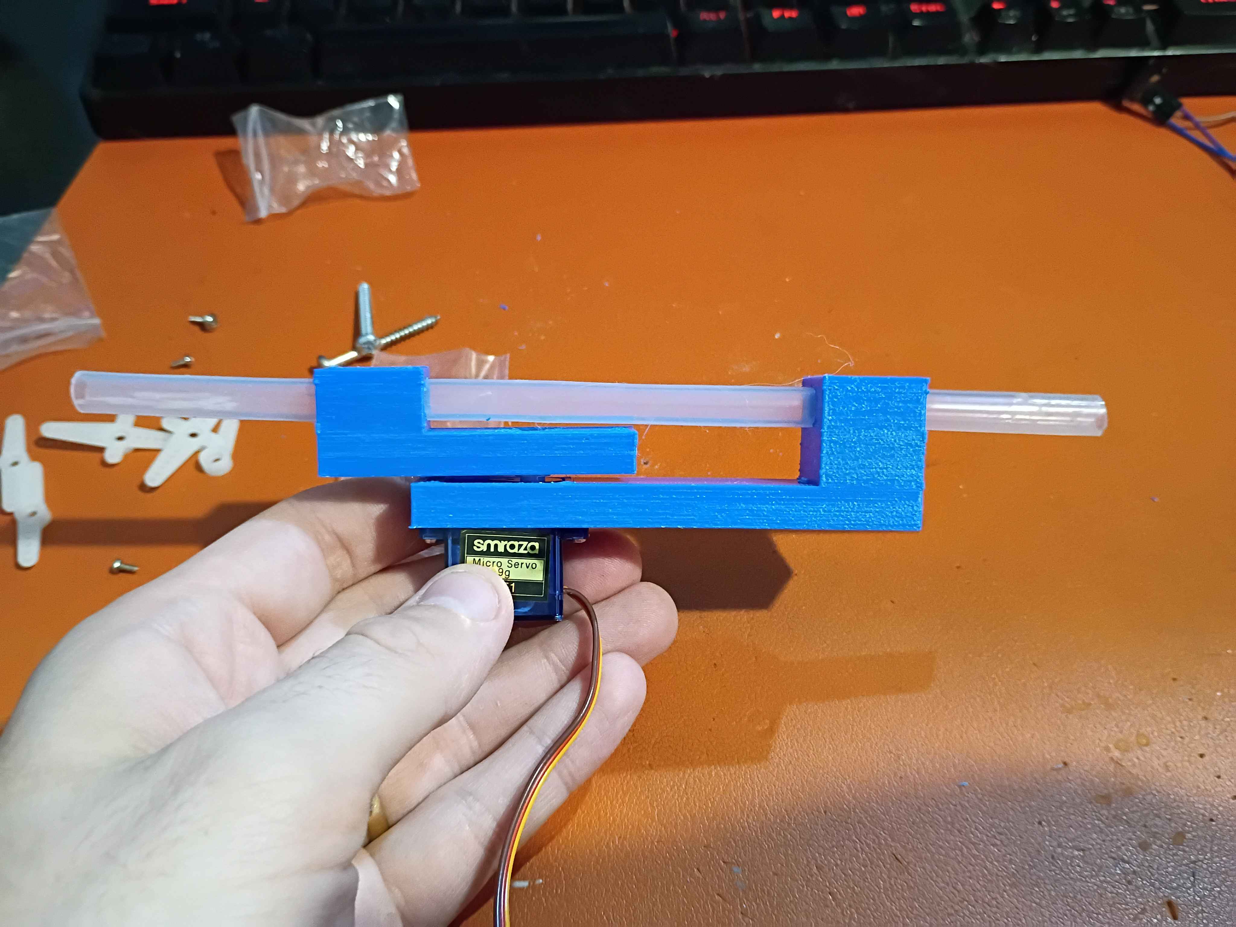
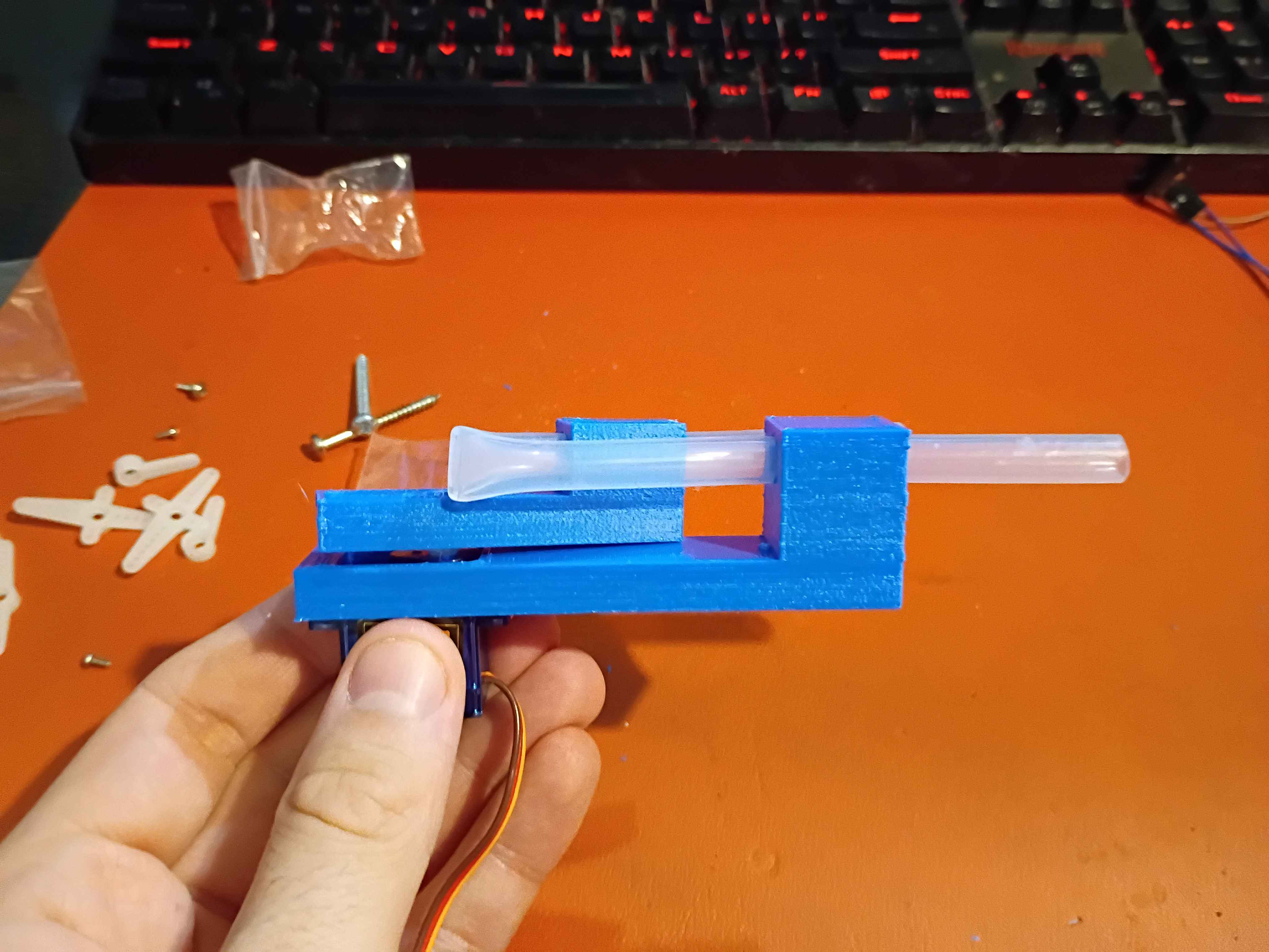
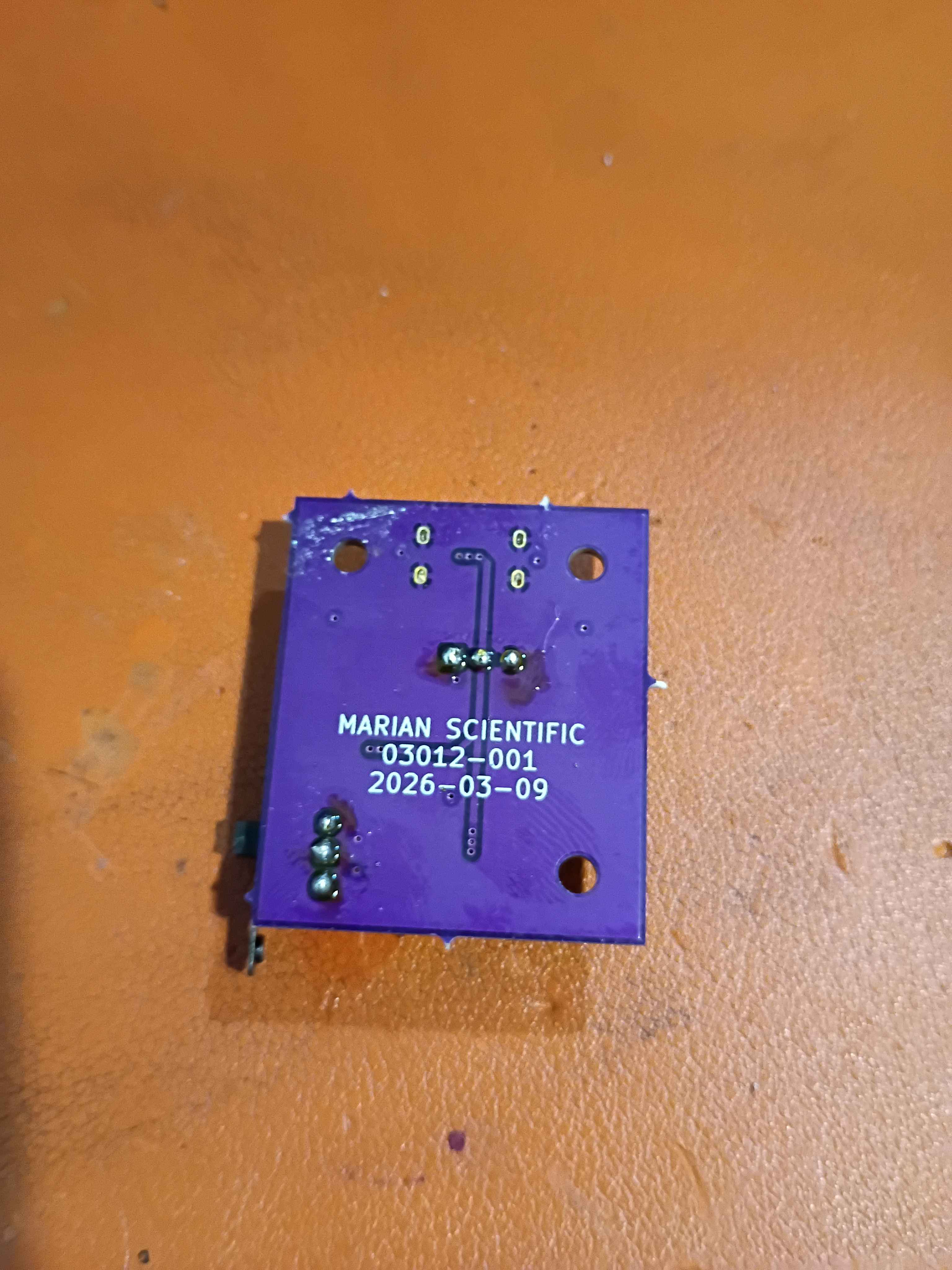
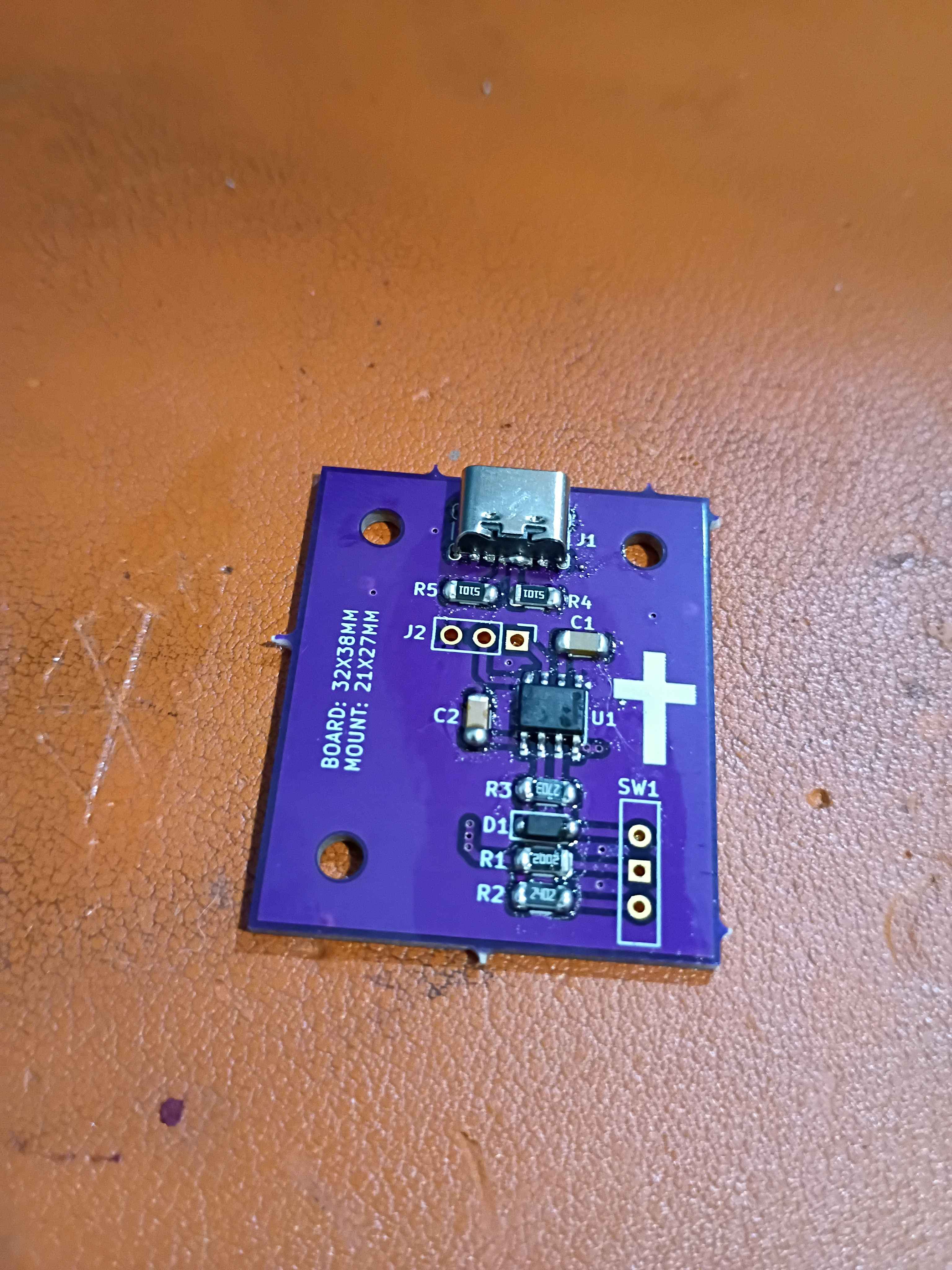
Soldered 03012-001 servo control board but with 20k and 24k resistors for R1 and R2 to reduce the range of motion to just 45 degrees. Printed and assembled corrected pinch valve geometry mark 1. Unfortunately there is not enough torque to compress even this soft tubing, so we will try something different. I don't want to pivot (no pun intended) to a beefier servo than the lowest-level hobby grade. See video of the fail. 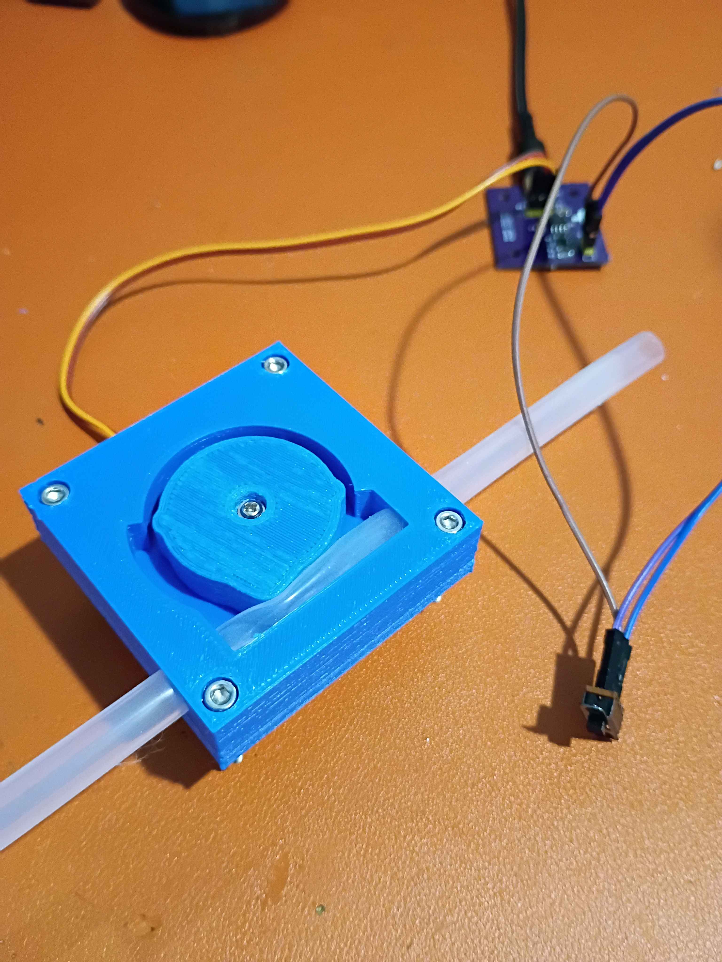
Designed 3-unique-piece wheeled sliding carriage for the gate. Printed and assembled some of the parts and tested on a short length of 2020 extrusion. 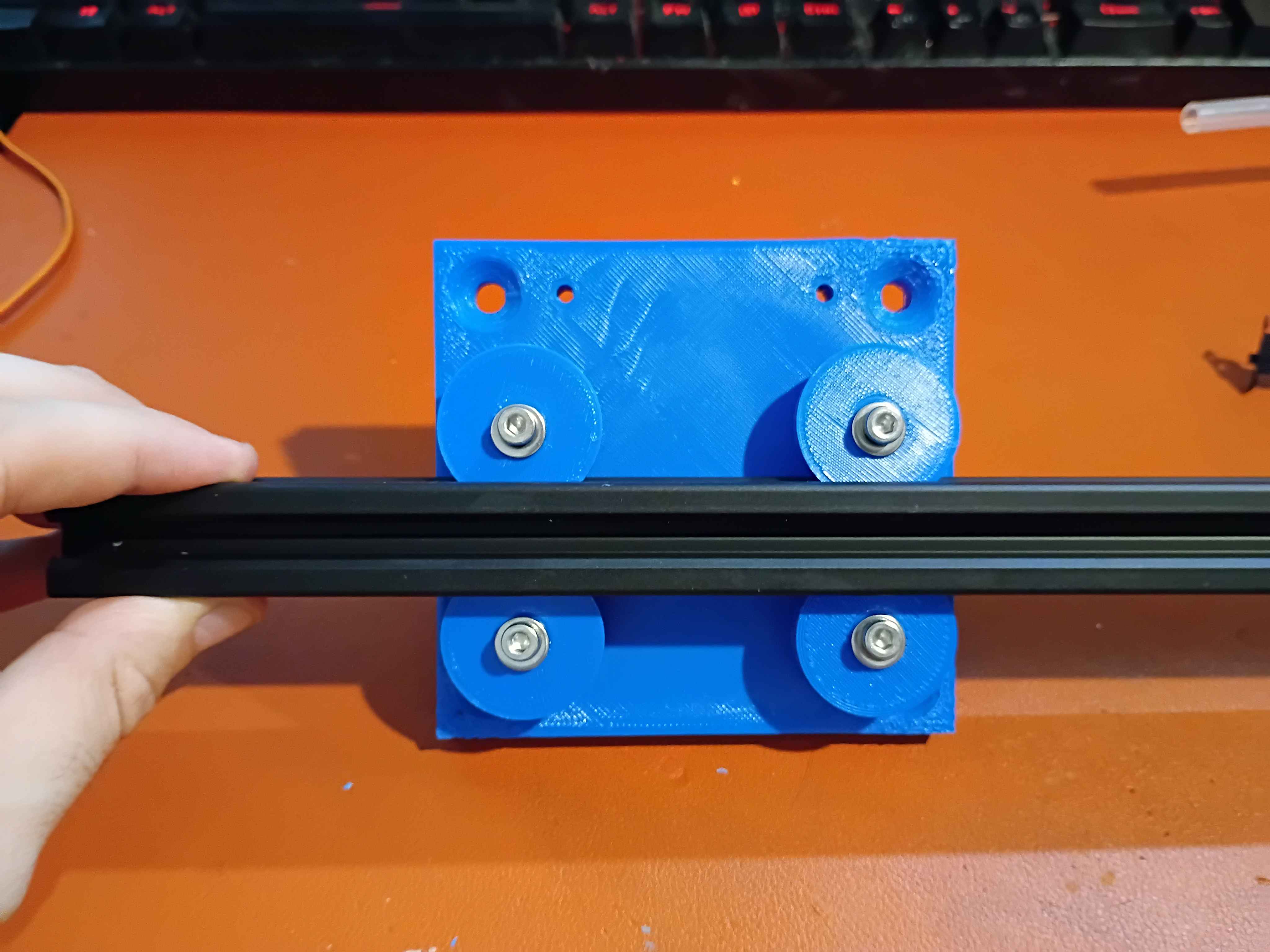
Printed out models and realized I need slightly less distance between the stepper mounting surface and the recess depth in the rotor. Also realized I need to improve bed adhesion before the next print.
Received 8mm OD 6mm ID silicone tubing and did a quick fit test on the 03015-001/2 pinch valve. It does successfully block air when close and allow air through when open, but I noticed a few things that needed to change, so I updated the model to a 3-piece 03015-001A/2A/3A. Started printing this new model overnight. 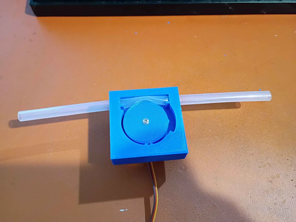
Designed housing assembly to accept 8mm OD silicone tubing and printed both components of the pinch-valve. Installed everything on a small servo. The clearances on the interlocking divots are too conservative; more engagement is needed. If the silicone elasticity/friction is not enough to lock the servo in the closed position, these divots will be required, but for now, the lack of engagement is OK. Ordered the softest silicone tubing I could find for a preliminary test. 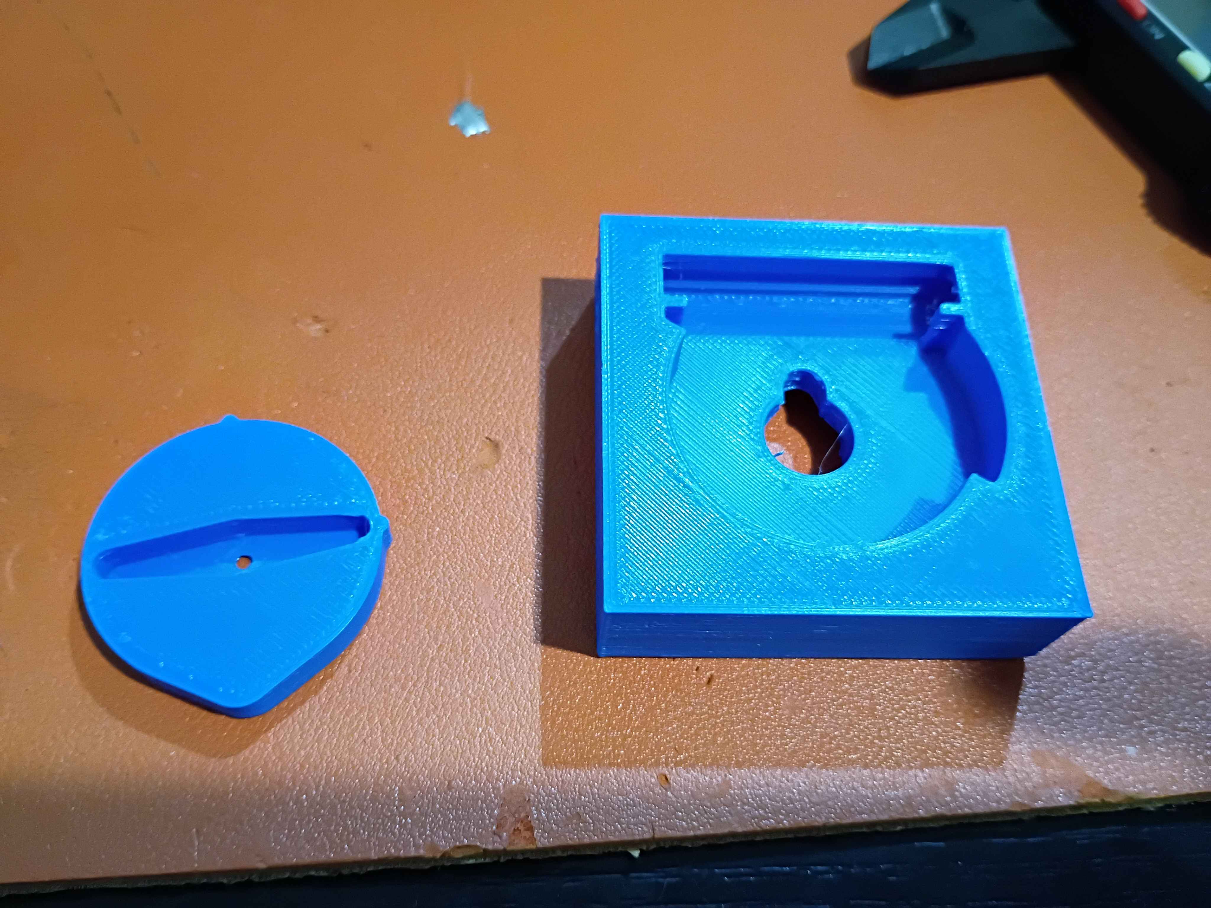
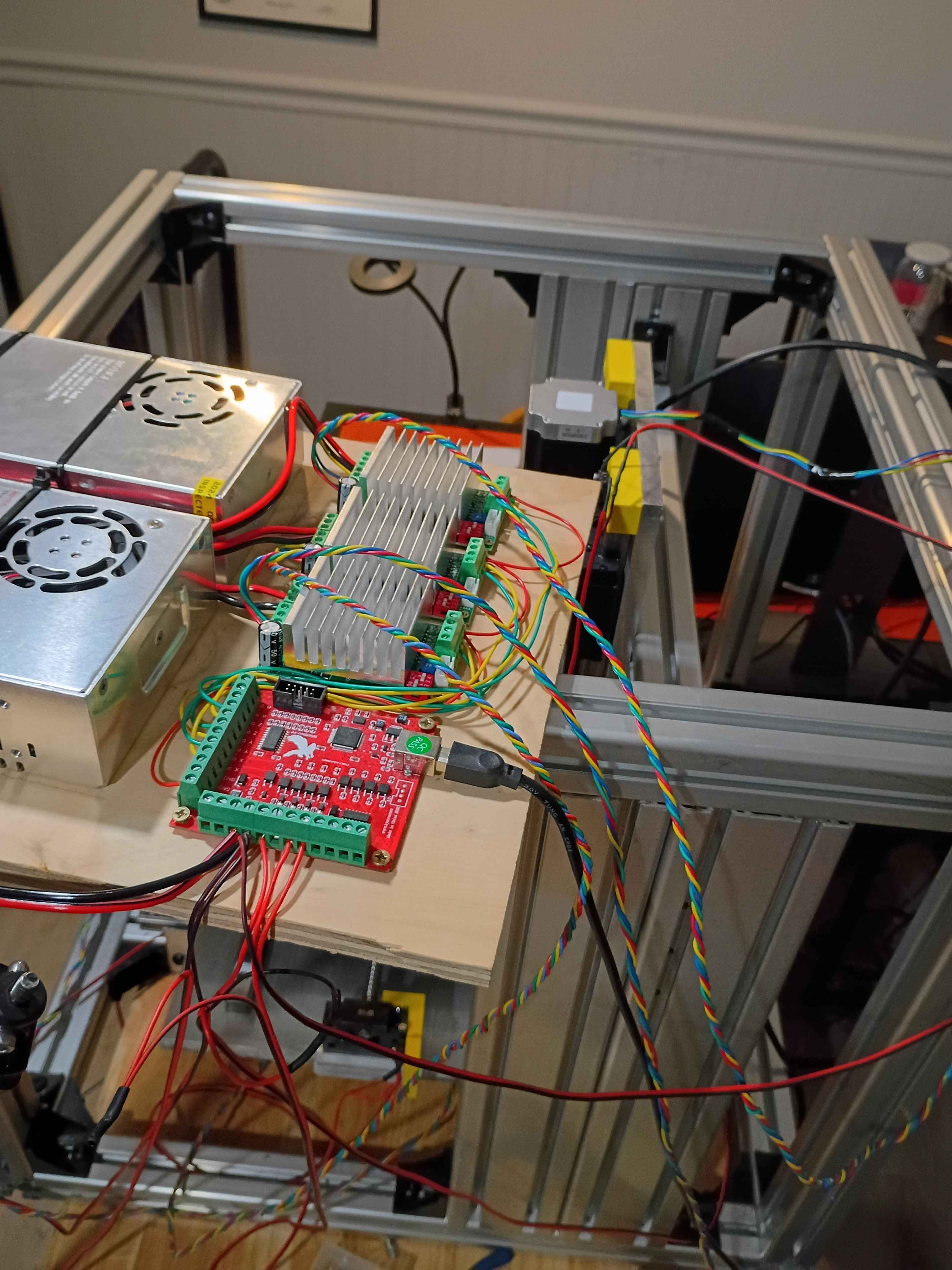
Routed wires more neatly. 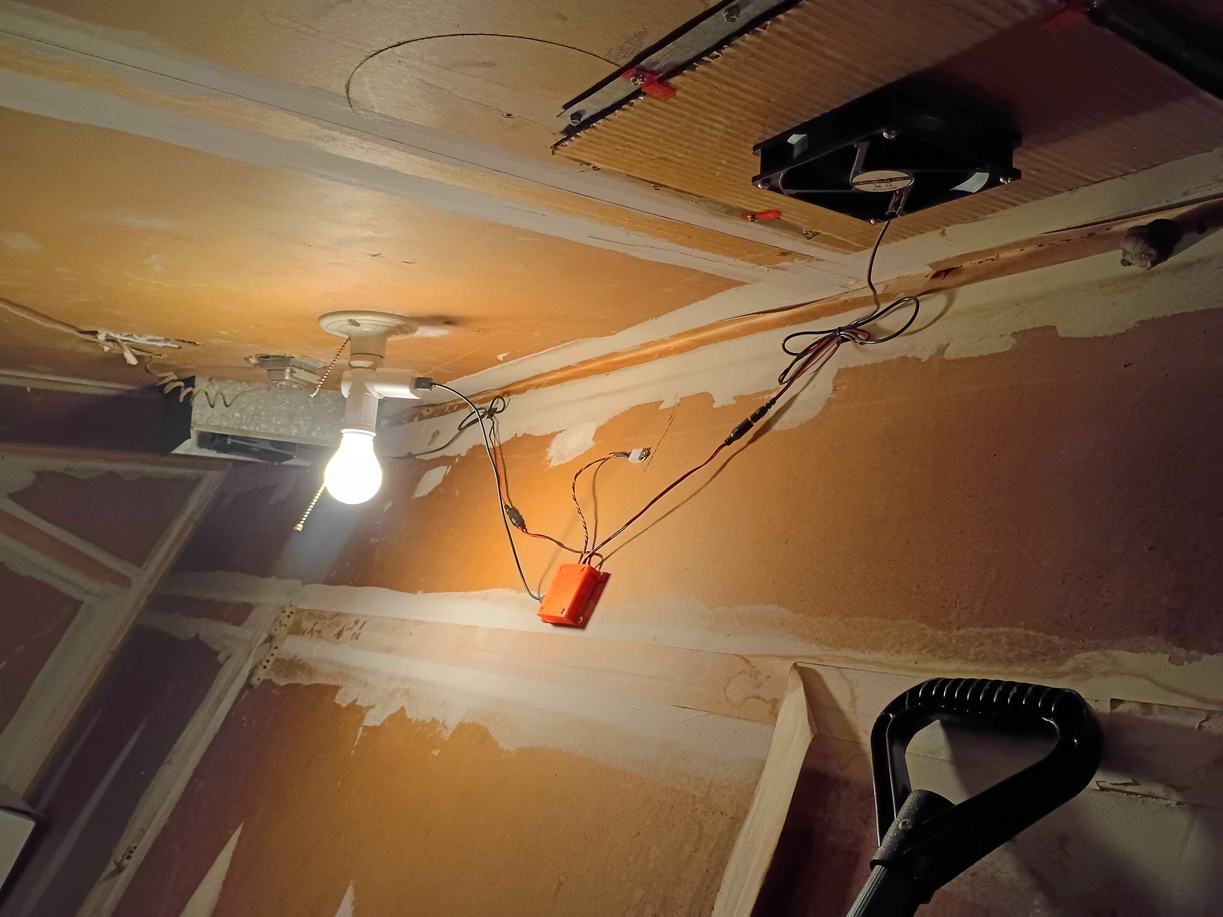
Designed test cam for test fit with servo arms. 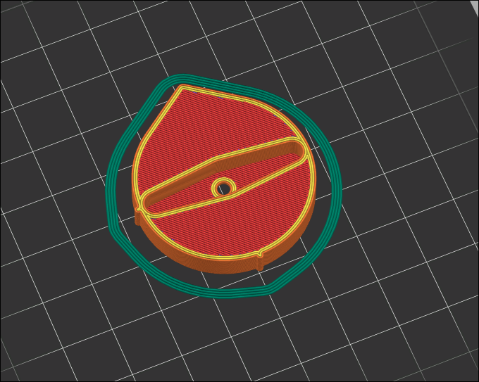
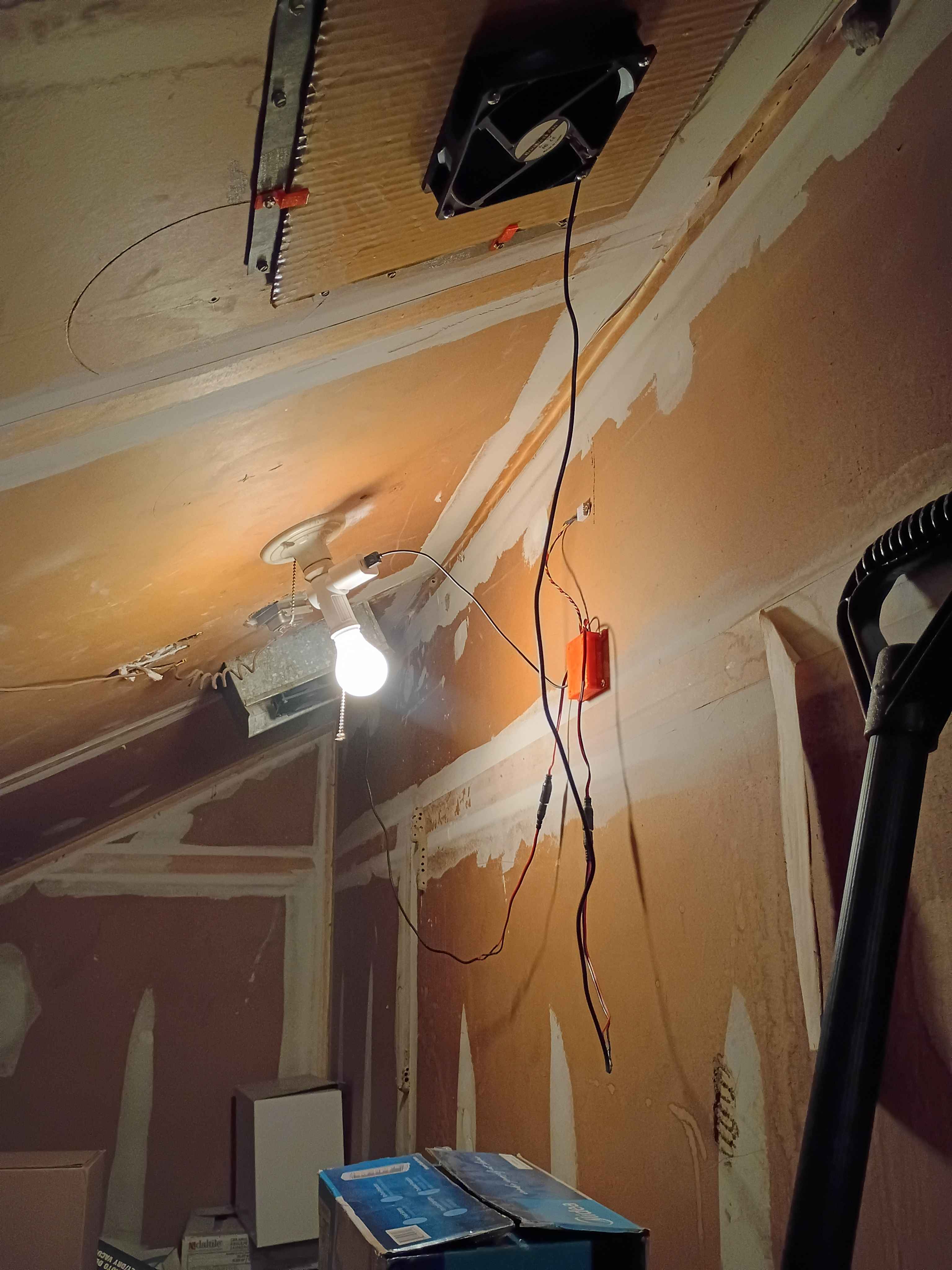
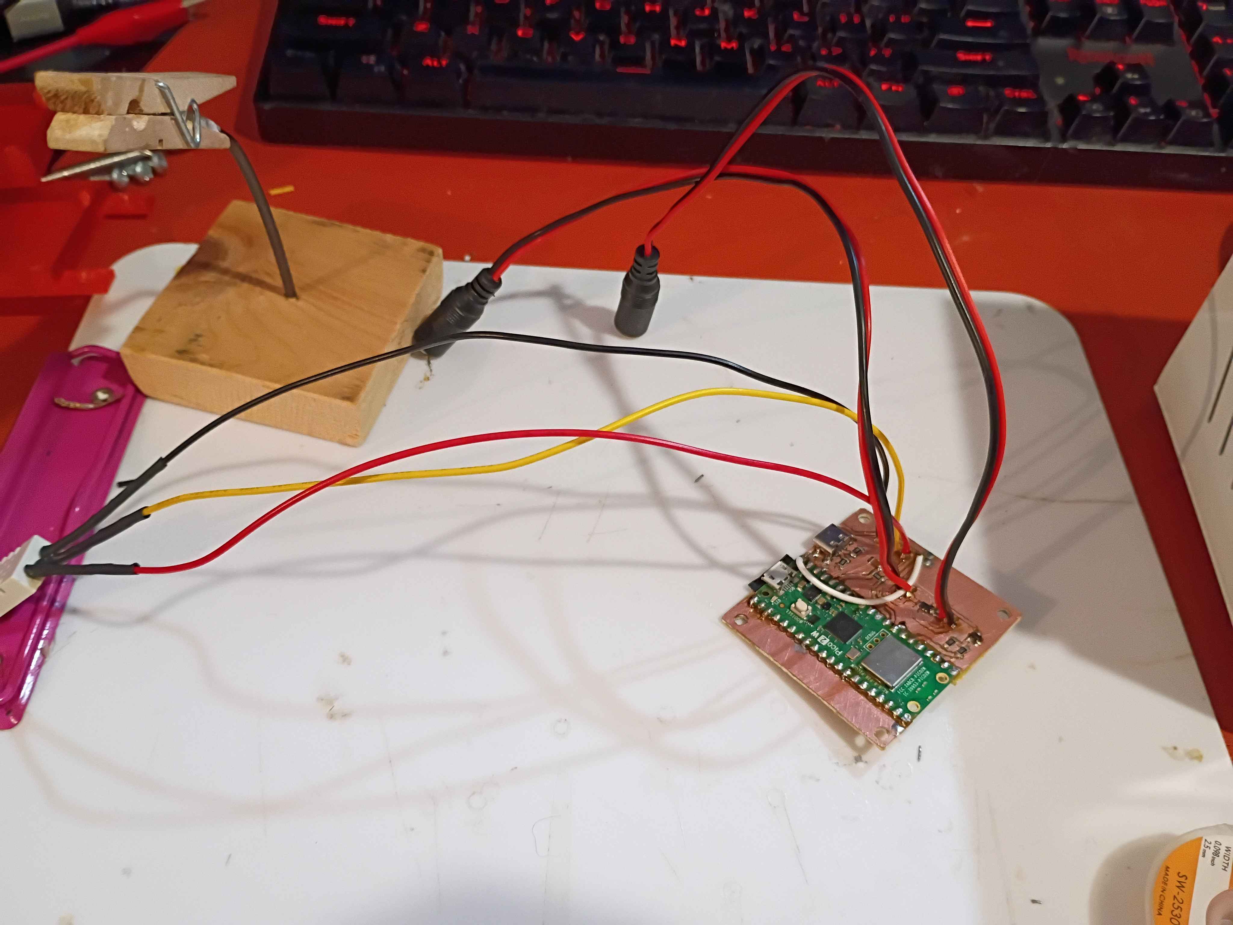
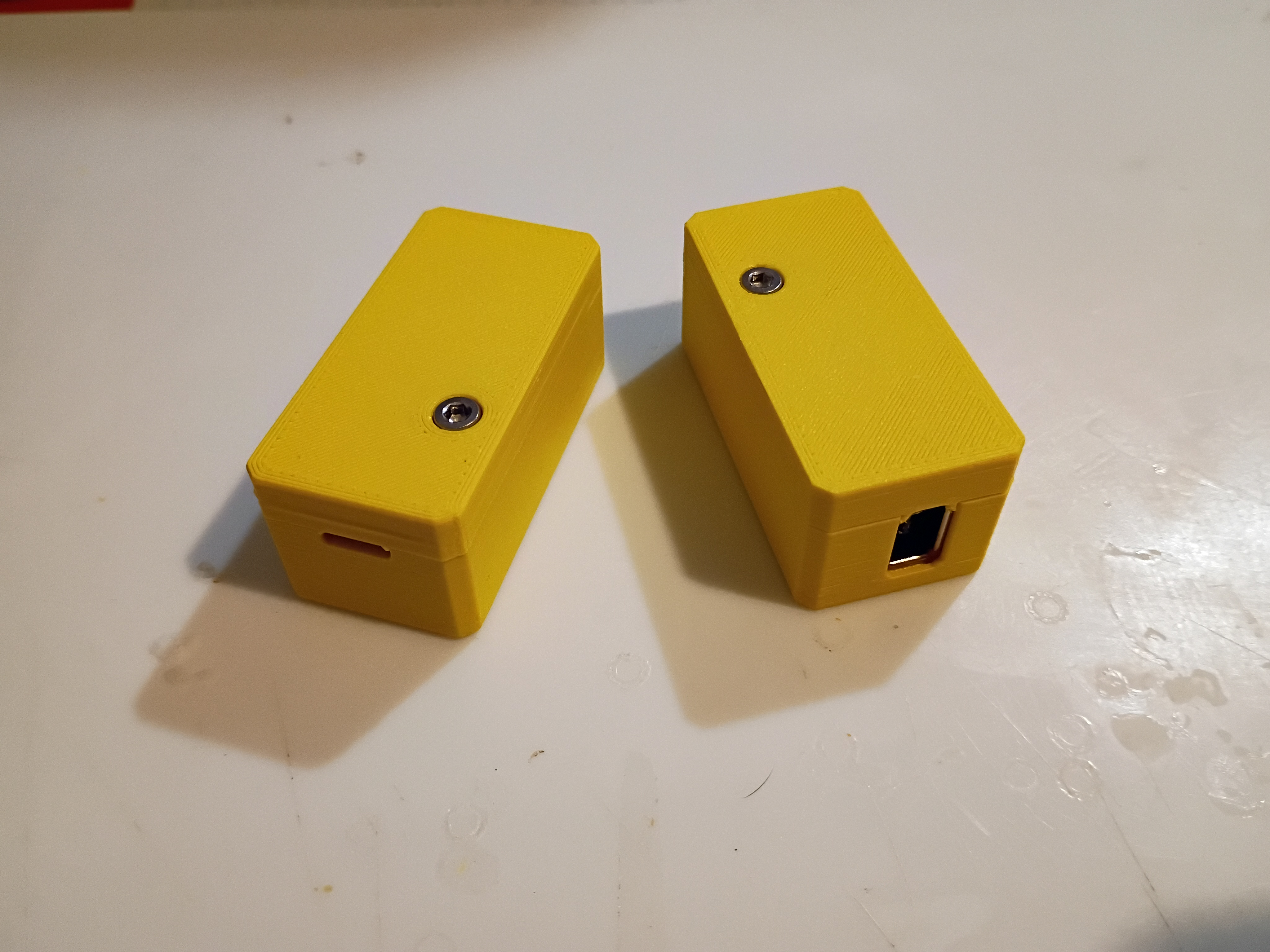
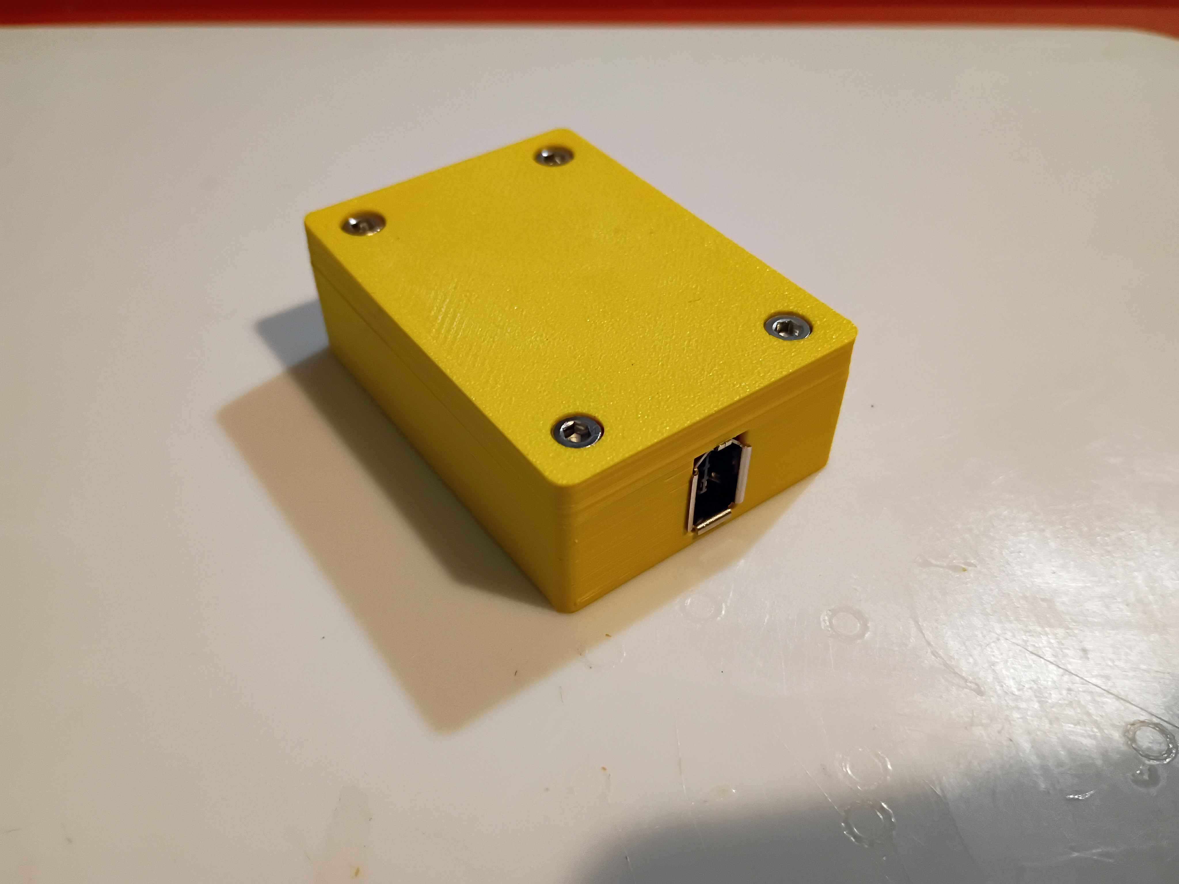
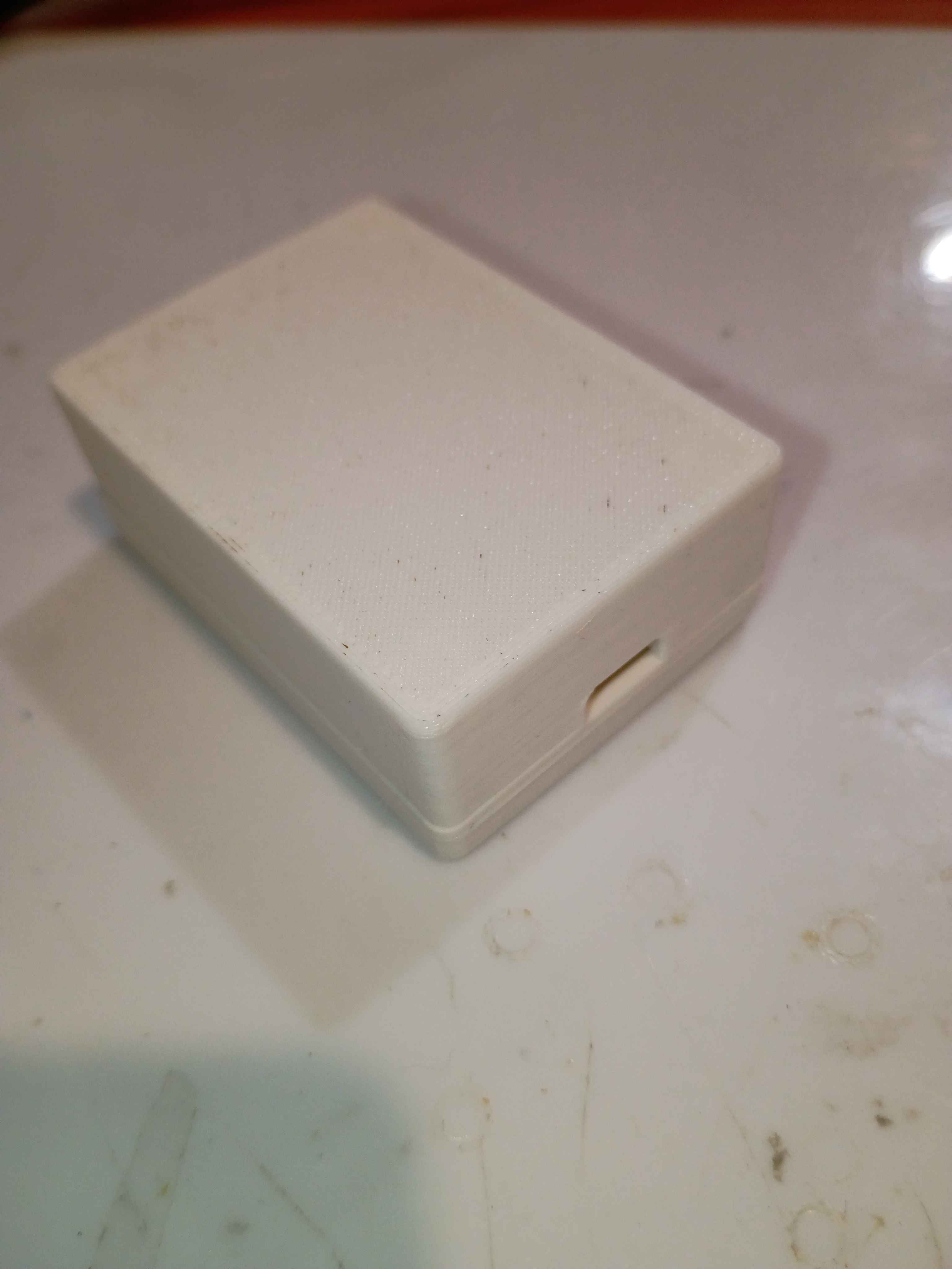
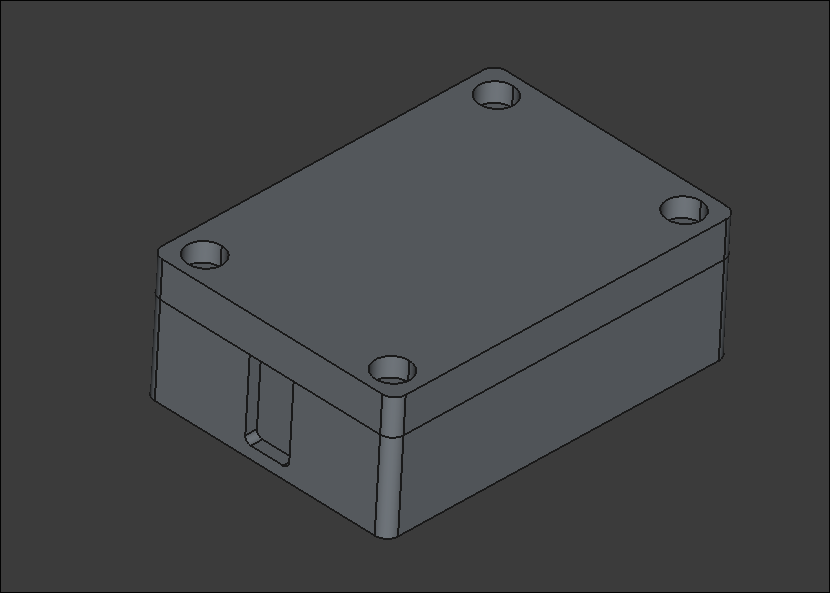
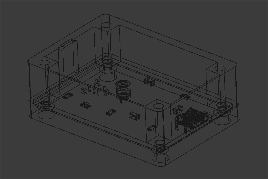
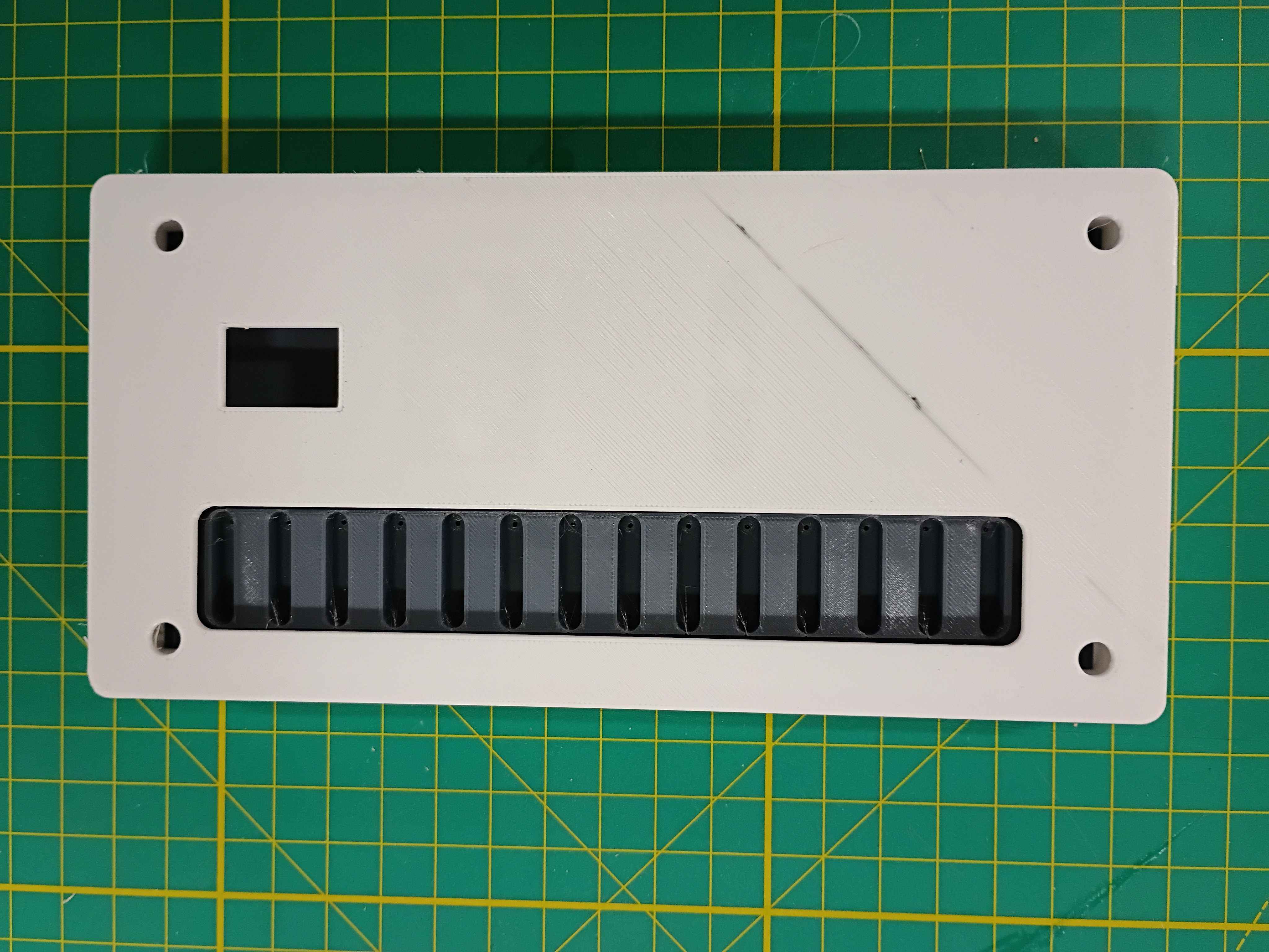
Decided to forgo the entire USB-C nonsense and just stick with the built in micro-USB on the Pico. Printed a new housing top to accommodate the different connector location, but I should still update the PCB design in KiCAD to remove the USB-C and fix a few other issues like the trace gap width and the pad extensions for the castellated contacts on the Pico. Installed the entire system and attached 2 fans to my roof ducts. One fan attachment used some 3D-printed screw adapters, and the other just used magnets. I used wood-glue coated cardboard as a low-cost water-resistant barrier on the ducts, which worked pretty well. The overall system worked pretty well. It dropped my attic temperature from around 90F to around 83F in 2.5 hours. 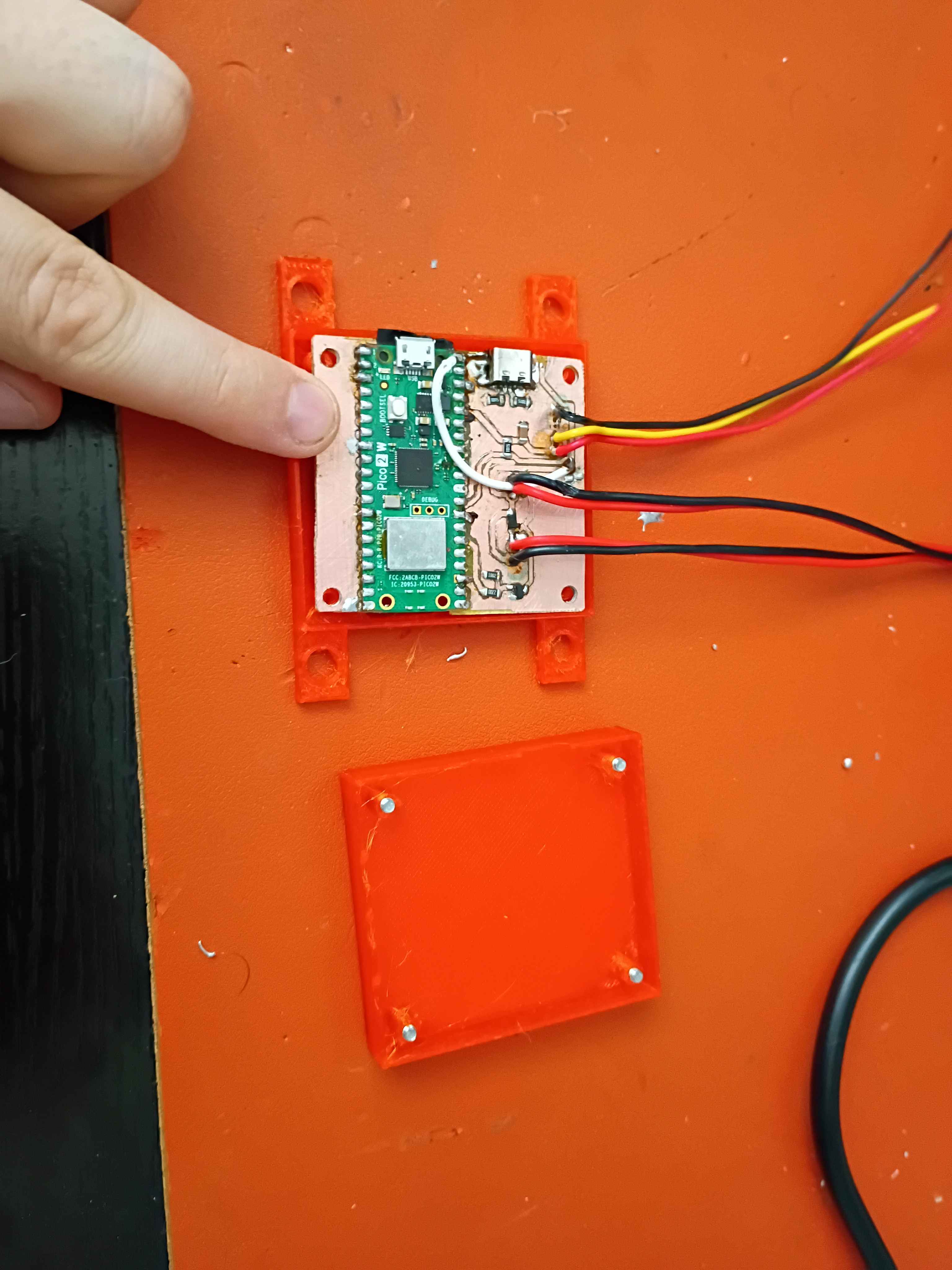
Fabricated the PCB with the usual process. For reference 1/2 tsp washing soda in 250mL water for the developing solution and 1 tsp sodium hydroxide in 250 mL for the stripping solution. Need to make the gaps between the PCB traces wider and put some insulator under the USB-C shield. See video. 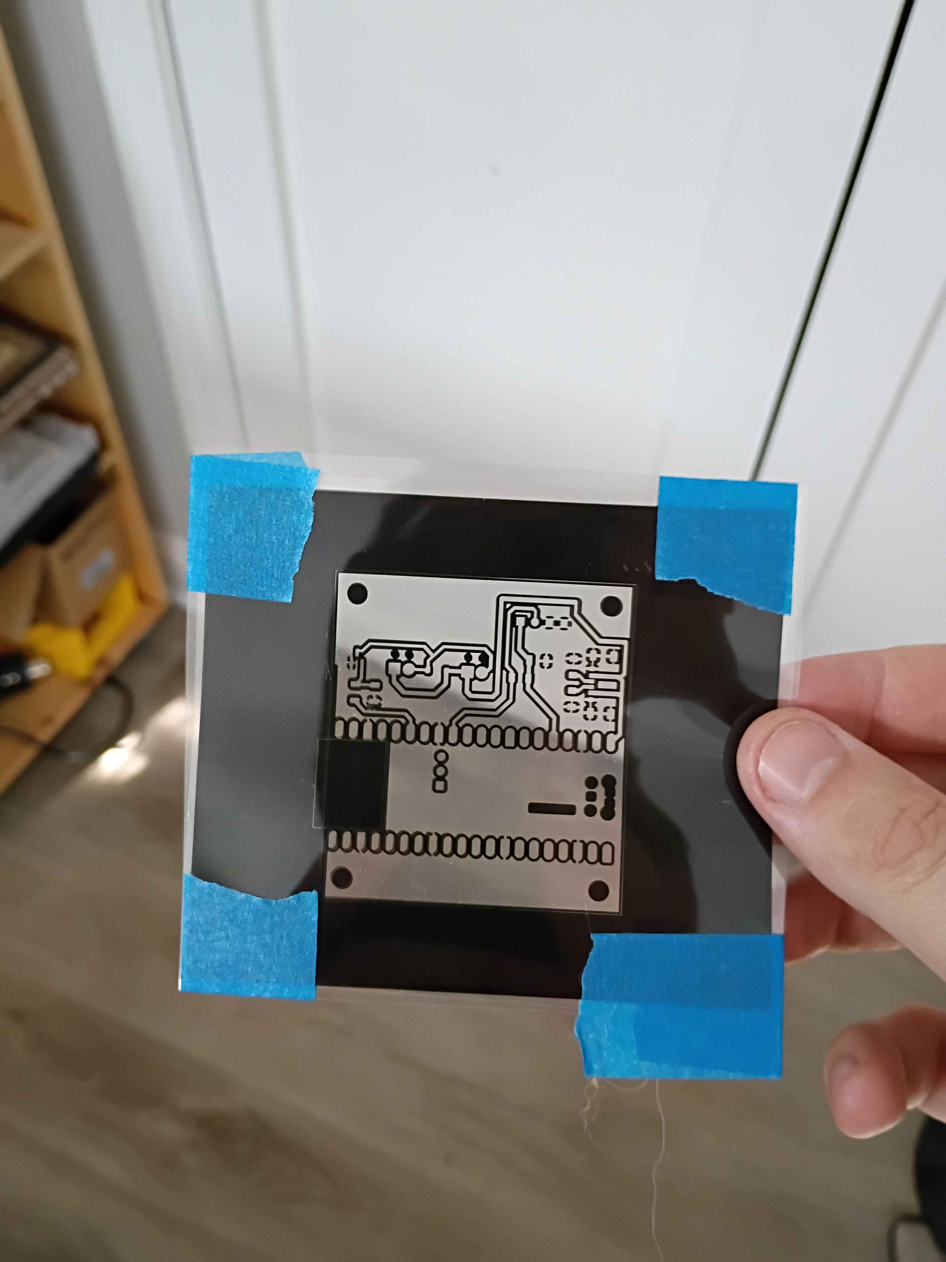
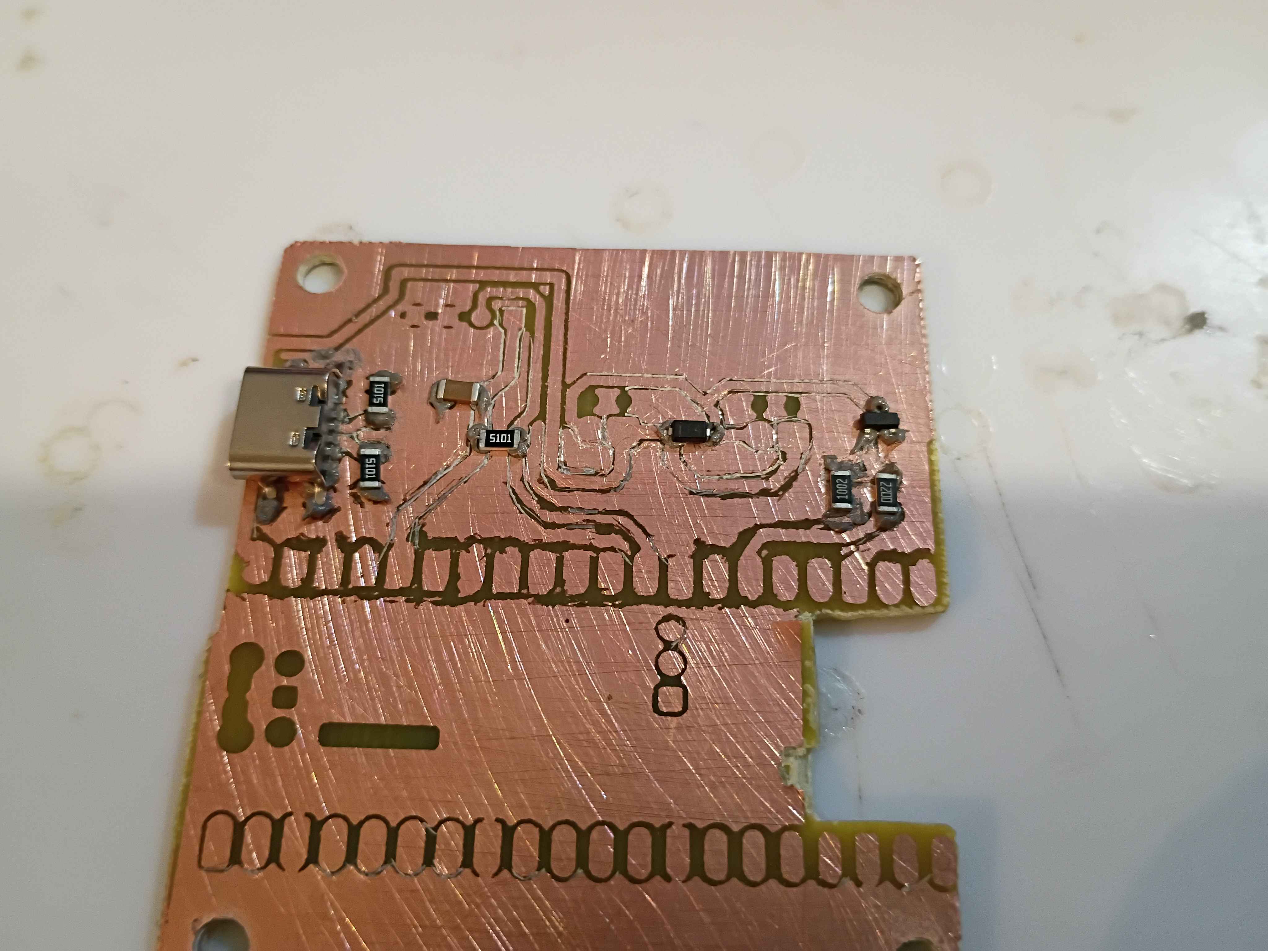
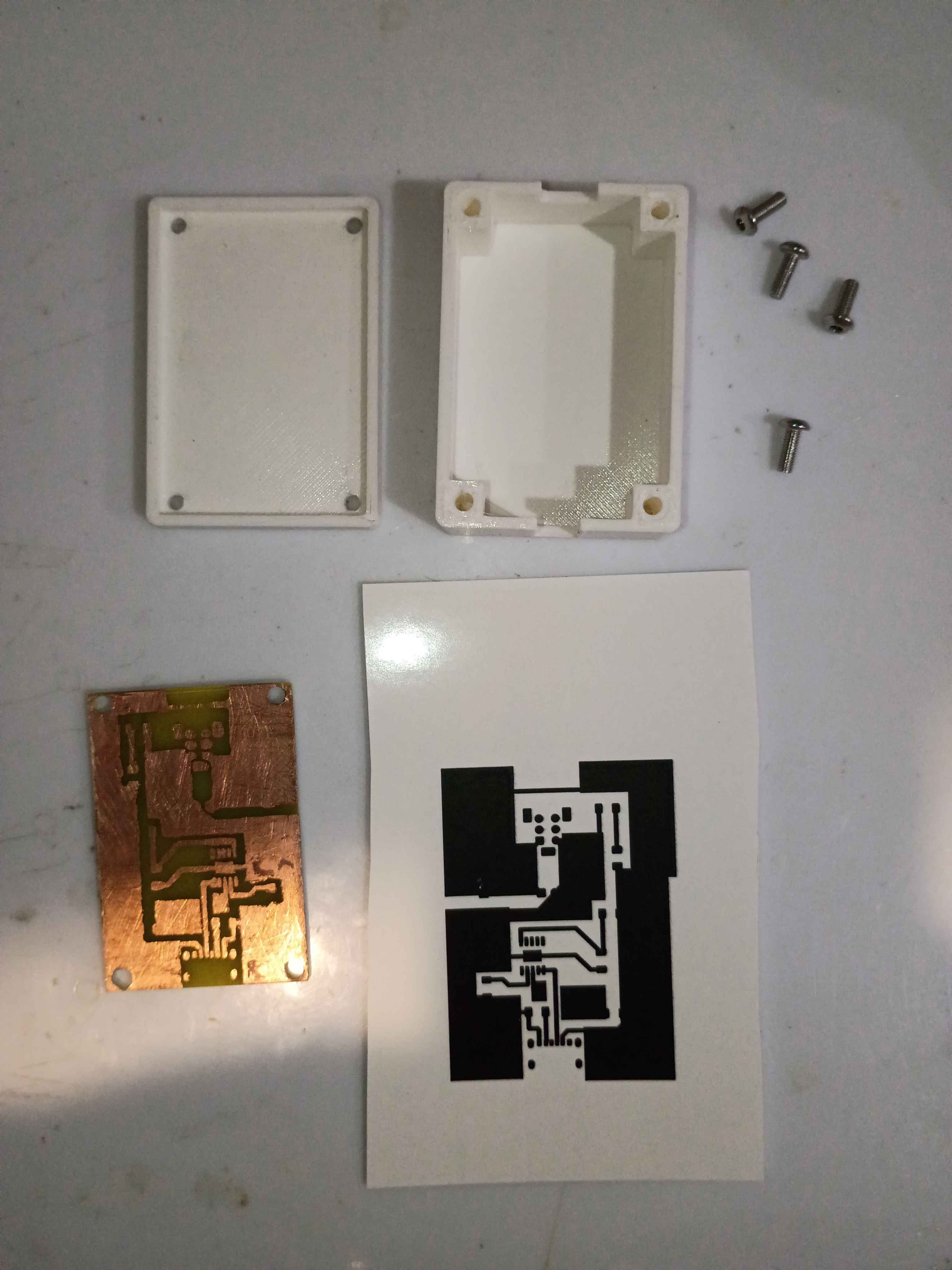
Made slight adjustment to copper traces on PCB design and printed a UV mask. Also made a slight update to the software to hopefully improve TCP connections. 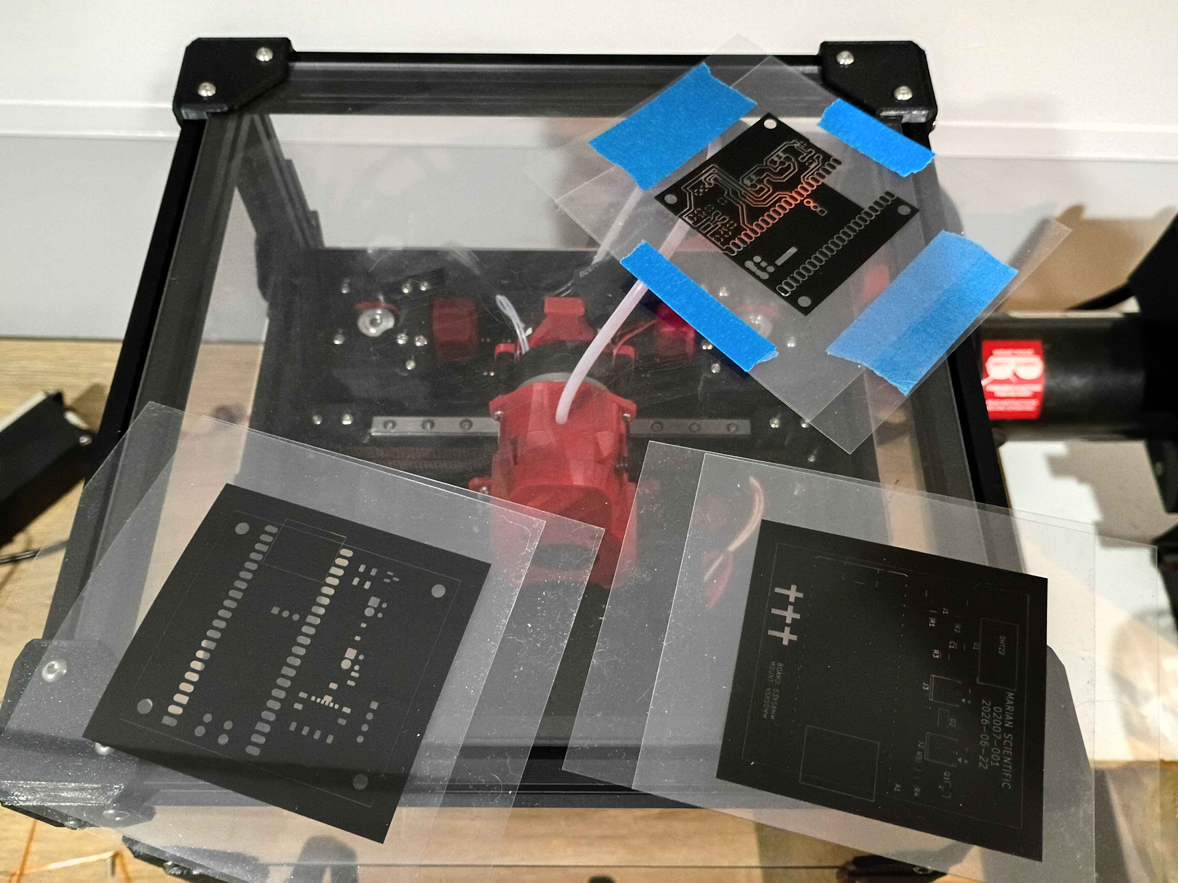
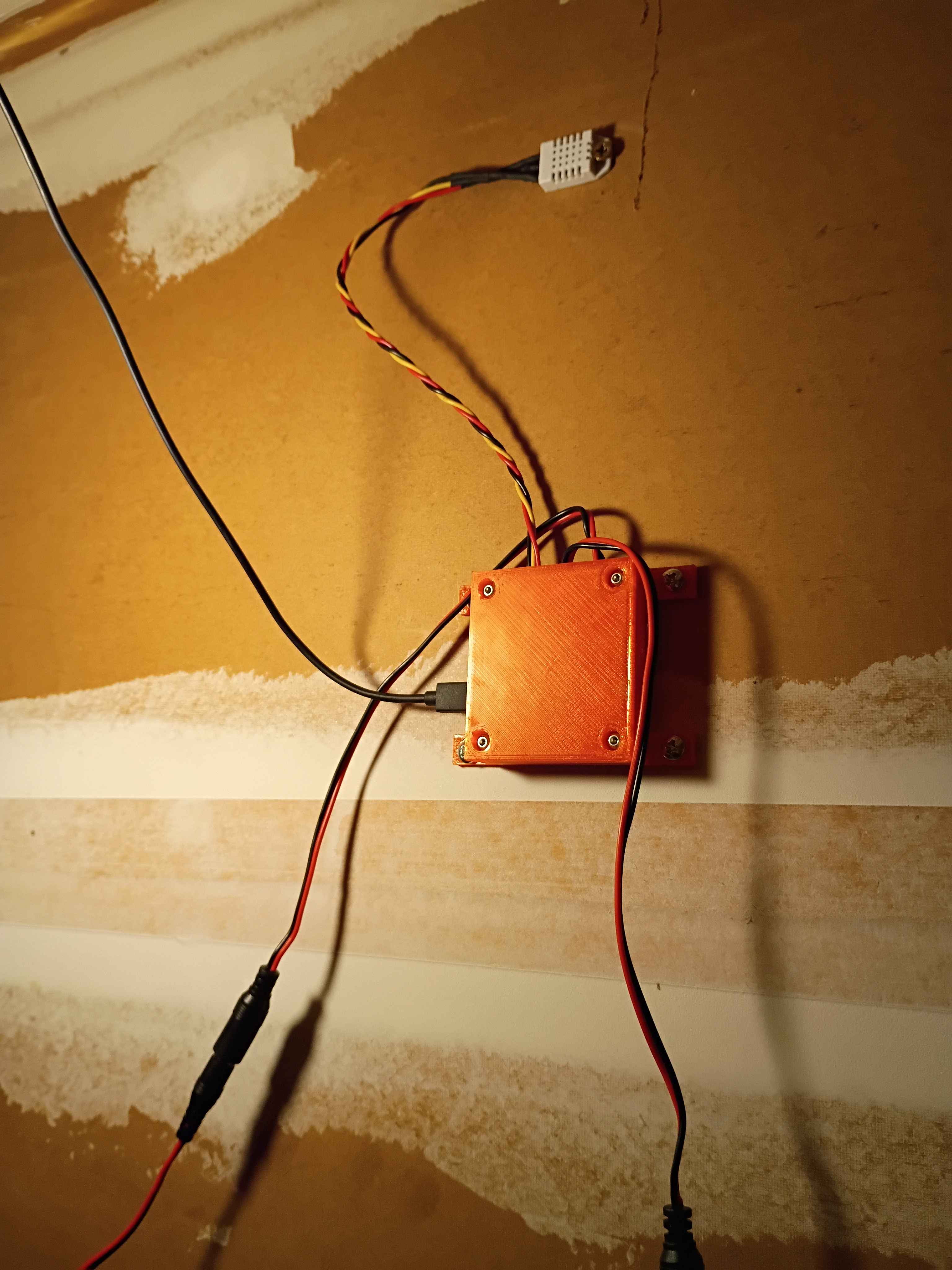
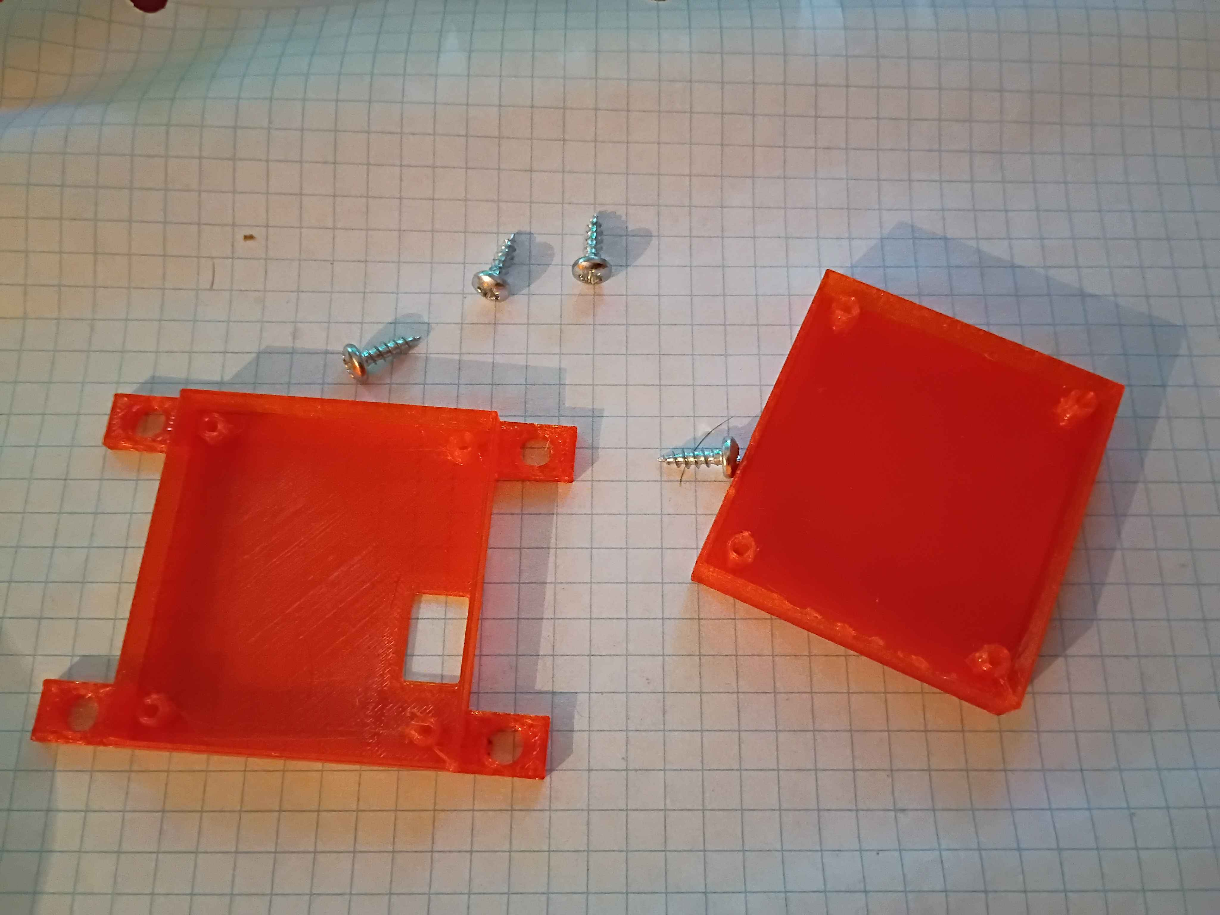
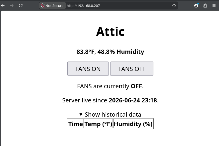
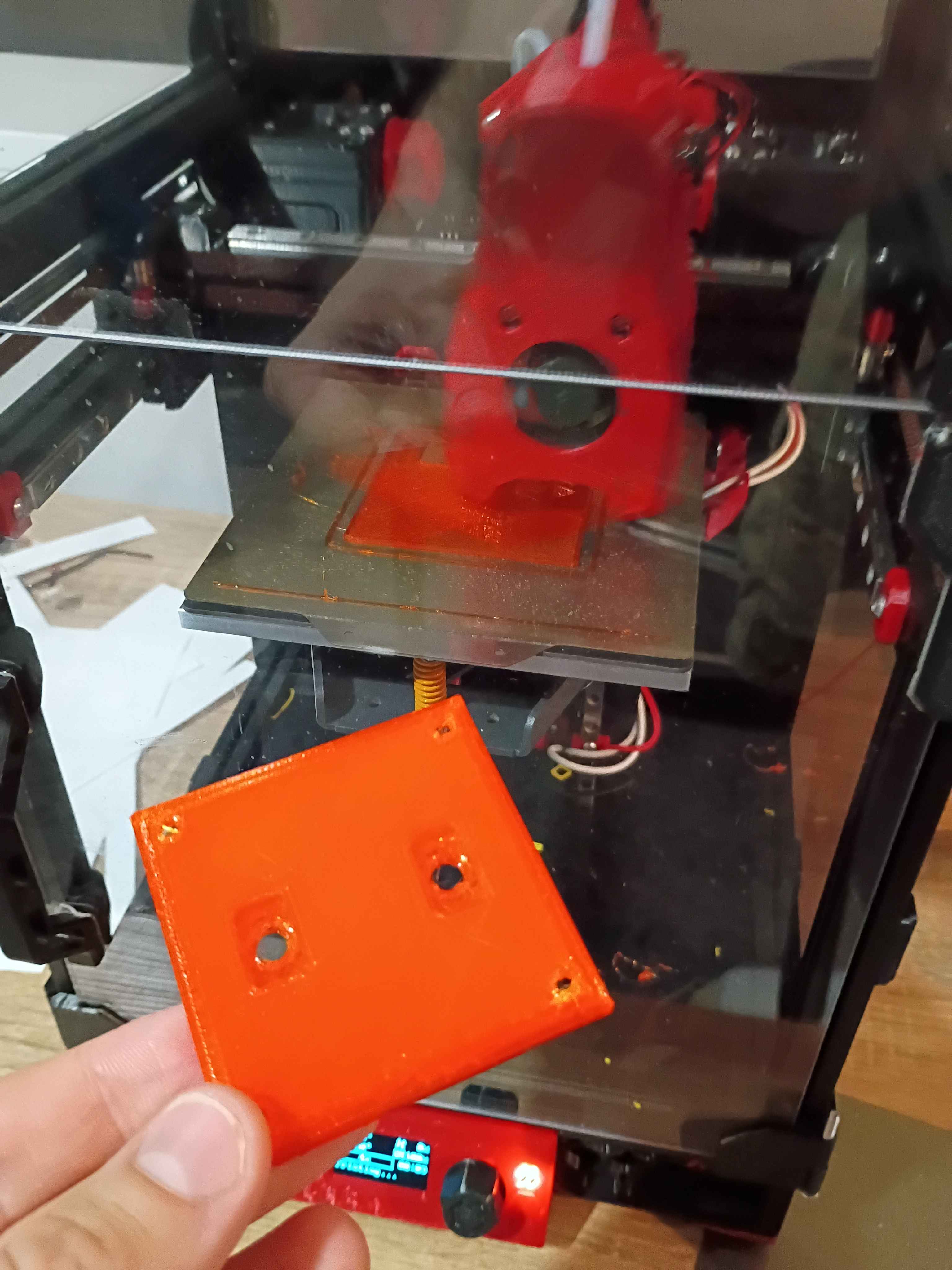
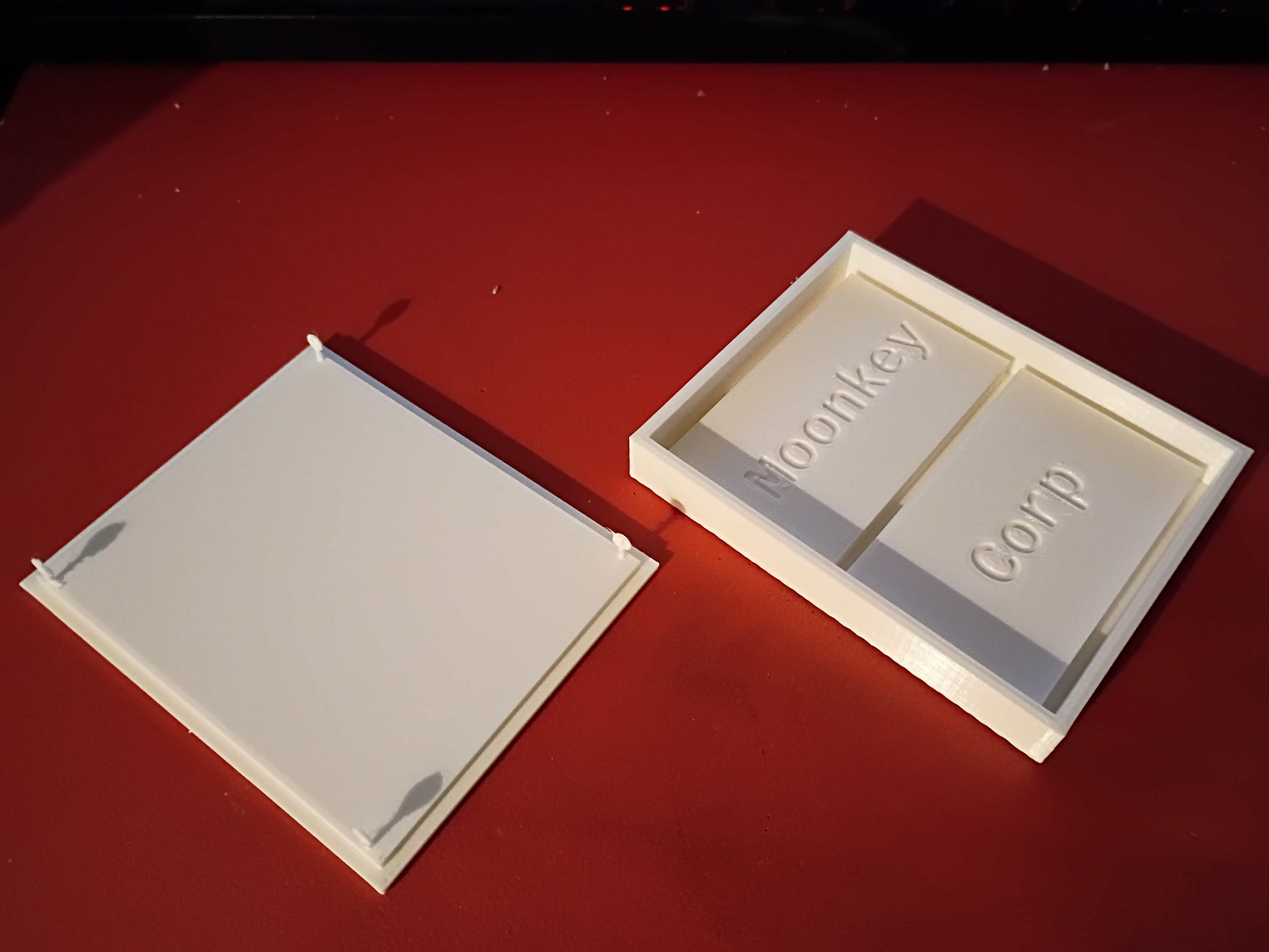
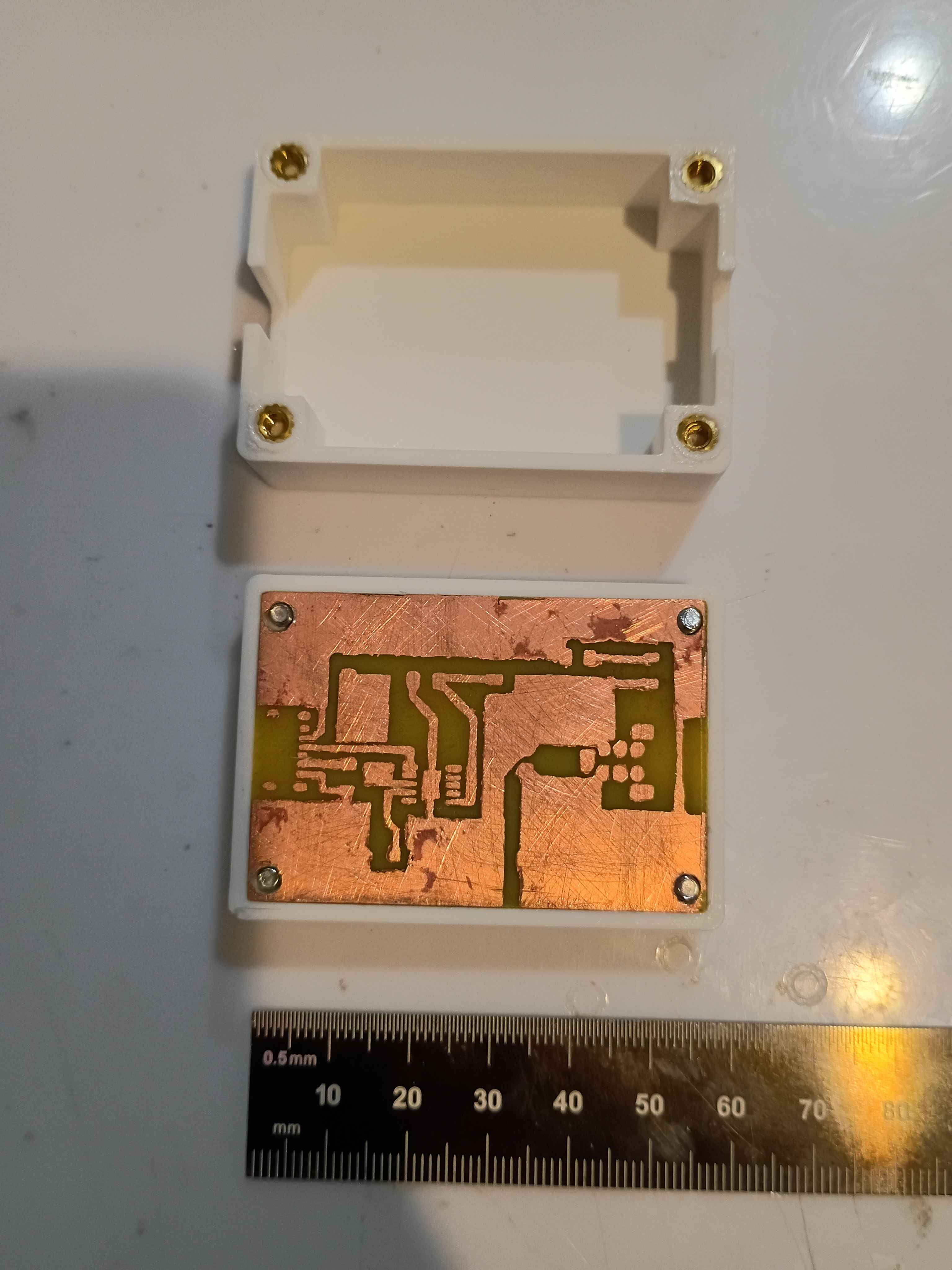
Updated housing model to have flanges to screw into the wall. Printed in translucent orange (best color) PCTG and found 4 perfectly sized screws in my jar. Updated the Pico web server code to show the server start timestamp, hide the historical data by default, and update to the final 30-minute delay in datapoint recording. 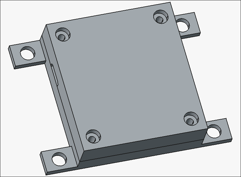
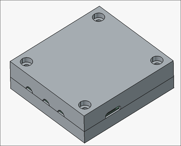
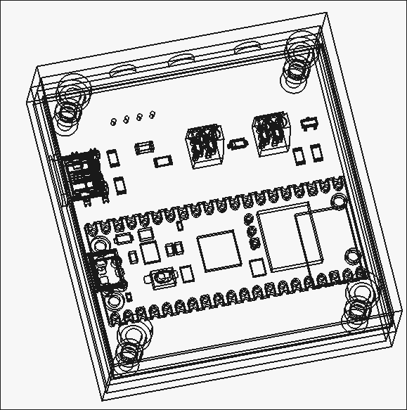
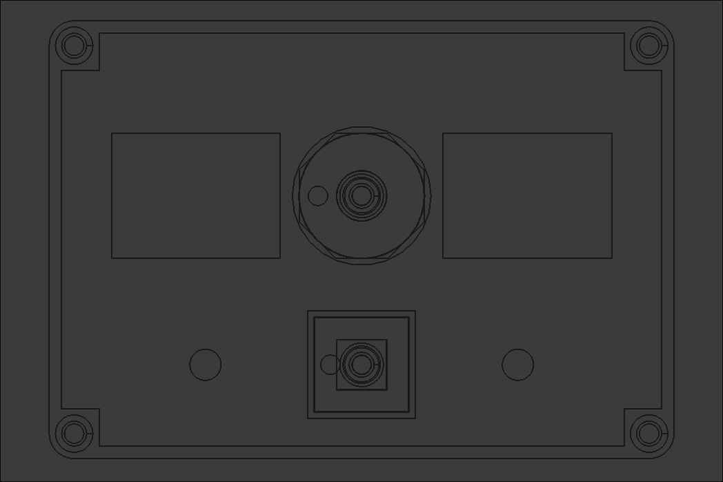
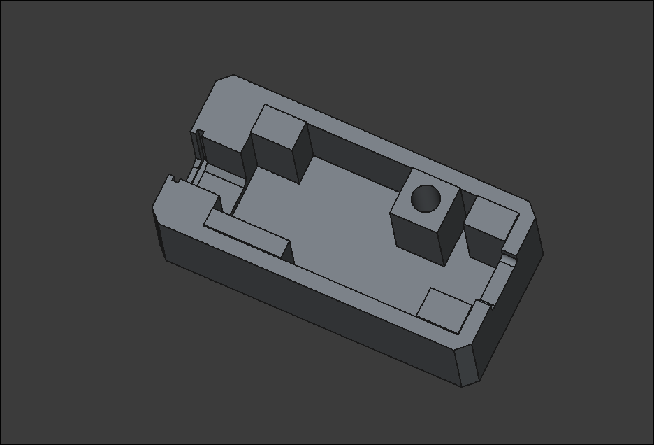
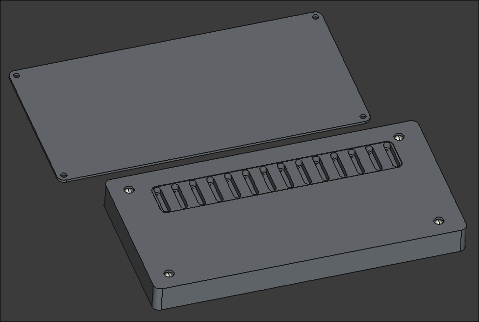
Designed 02007-002 and -003 housing components. There are holes in the box for the antenna (unnecessary), USB-C connector, motor wires, and sensor wires. 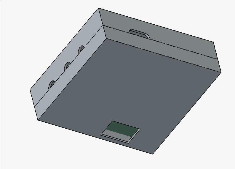
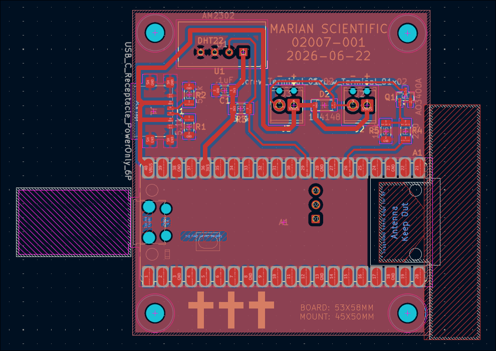
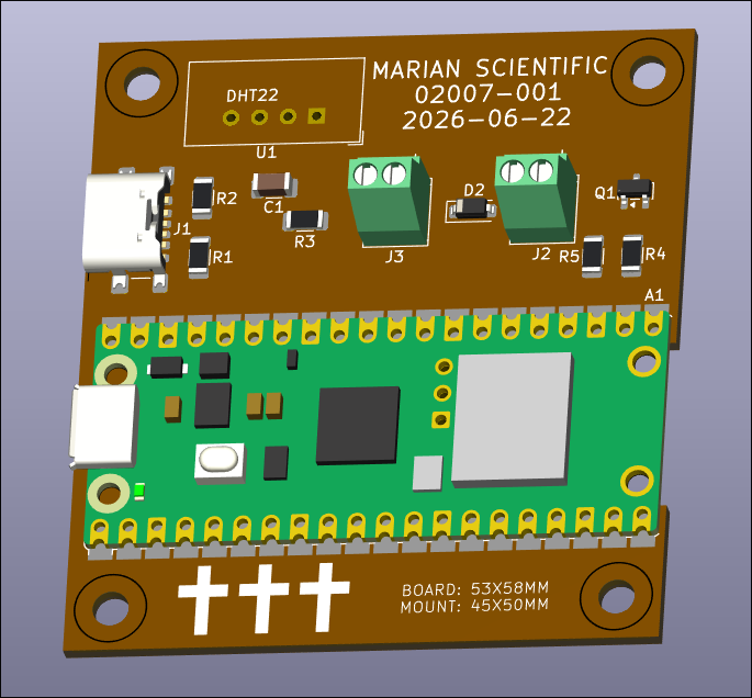
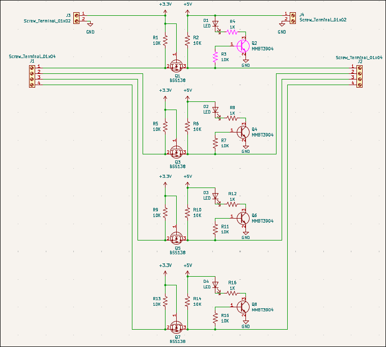
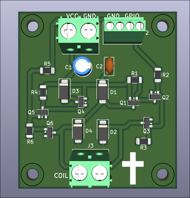
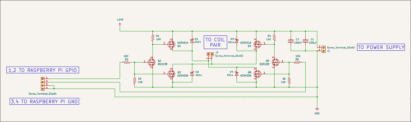
Designed circuit schematic and laid out PCB design for the control unit. 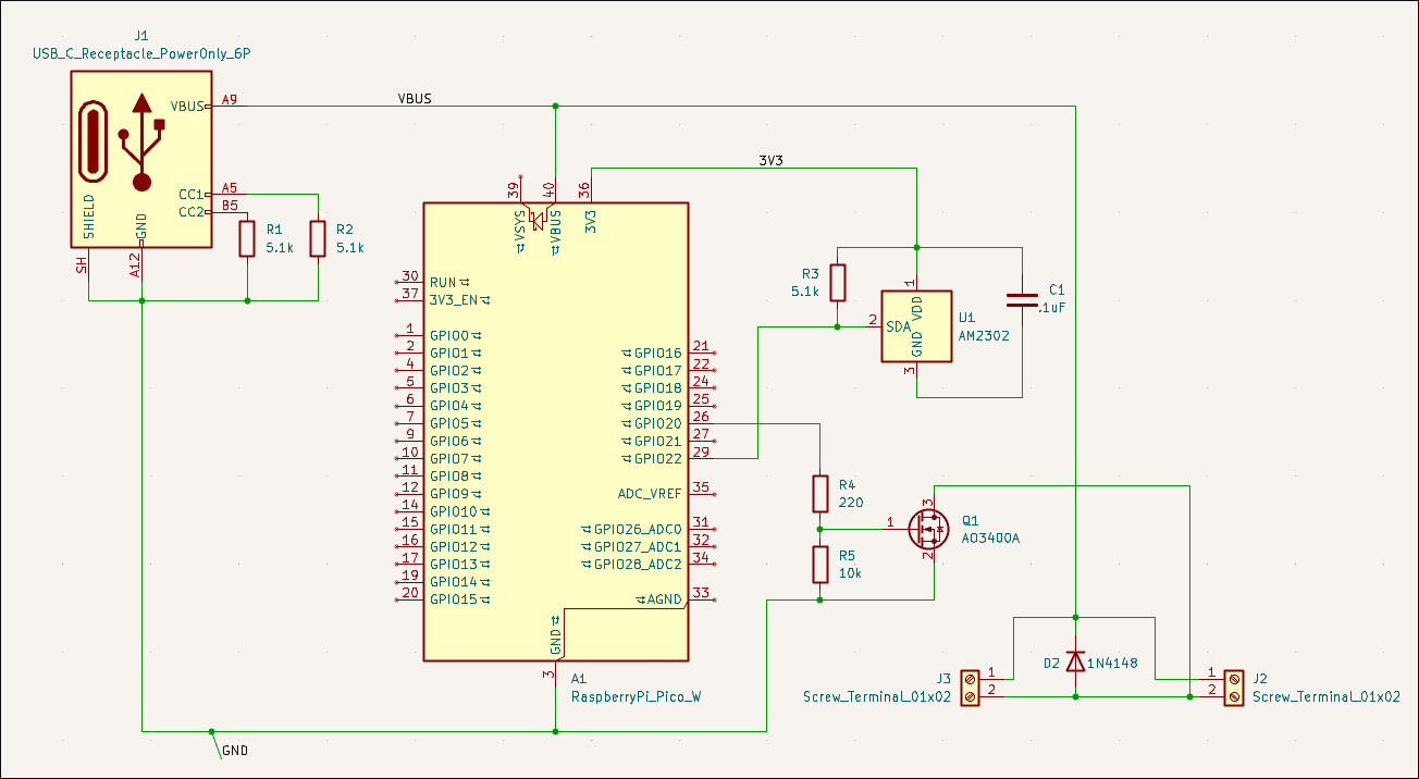
Spent a while getting the connection to the time server working. Attached UI image shows a datapoint every second for testing purposes, but will probably be every ~30 minutes in the live version. 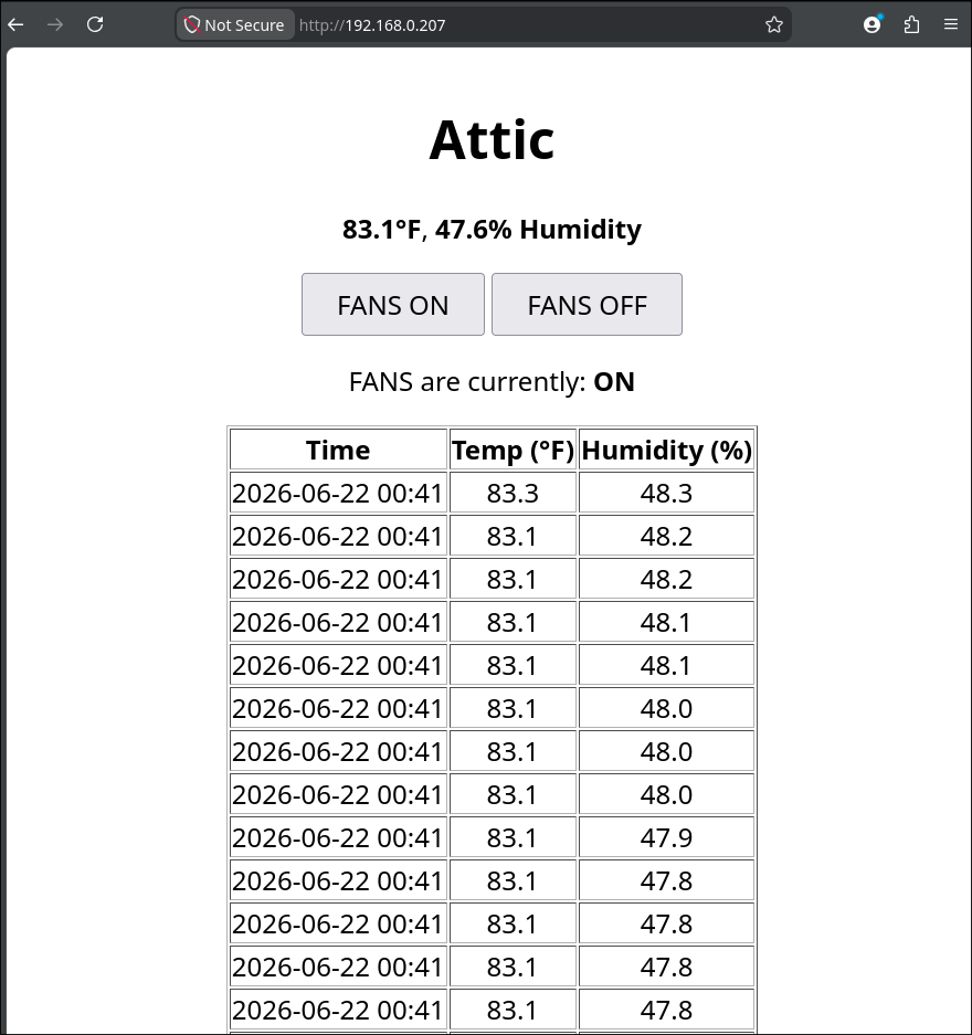
Had to disassemble, repair, and reconstruct the x-axis since the terrible octagonal garbage nut was terrible. Successfully tested afterwards. 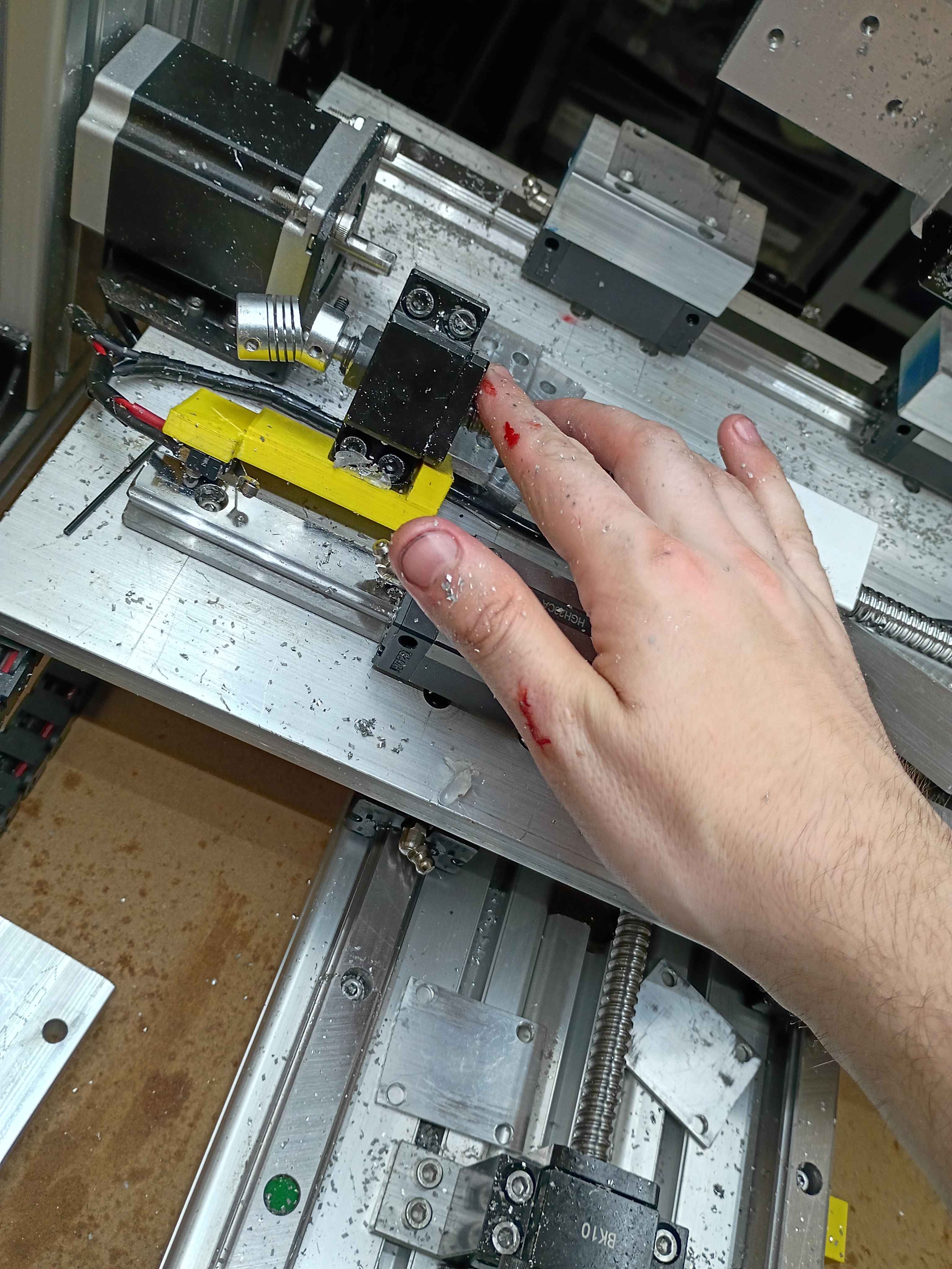
Got the preliminary software mostly working. Ignore the broken UTC date, having some issues with the time server. It allows GPIO control of a Pi Pico 2W thru a webserver, and that will eventually toggle on some small vent fans. It also reports the temperature and humidity. I could eventually add logic that turns on the fan based on the relative temperatures inside versus outside. 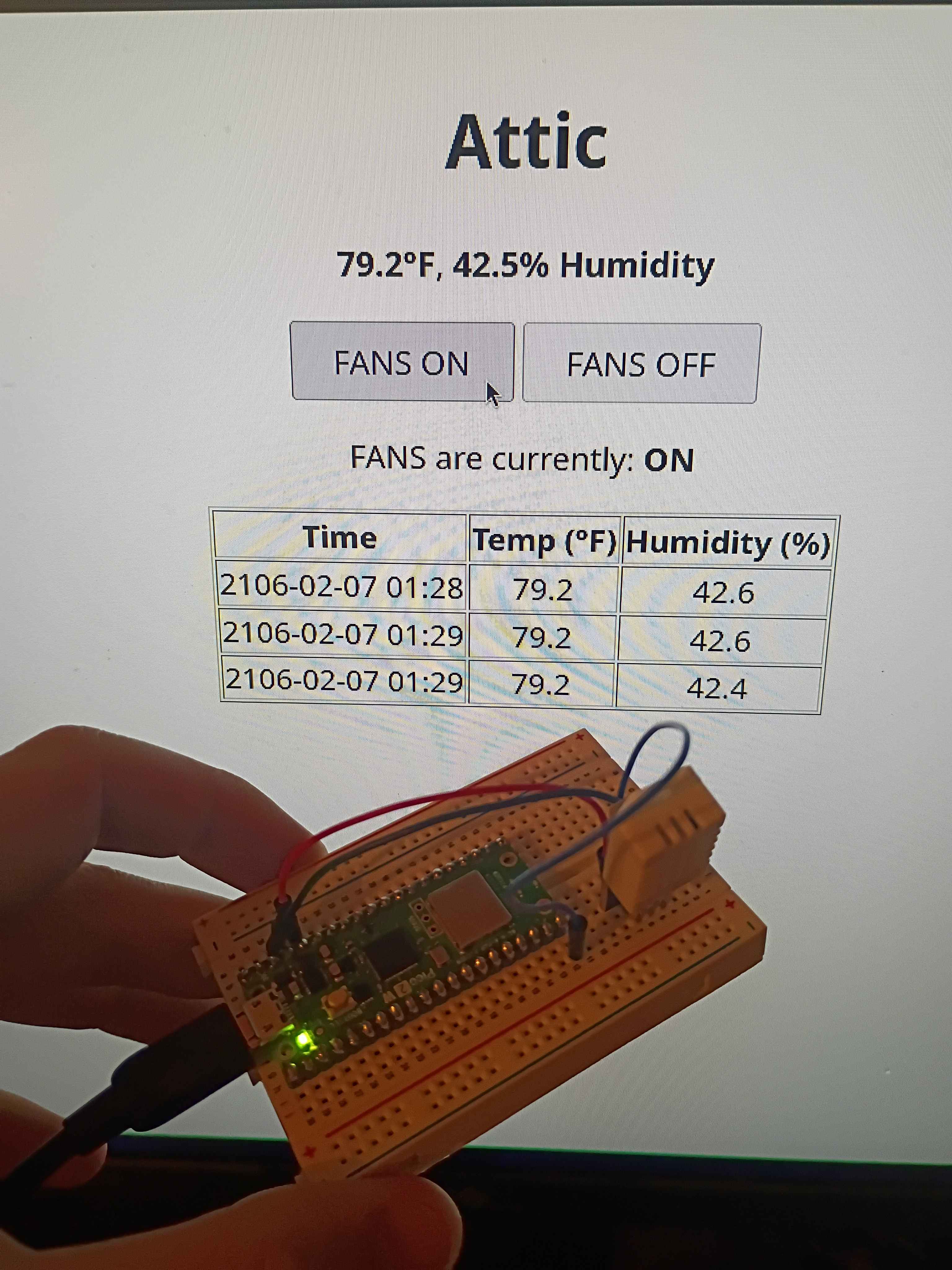
Vibe-coded GPIO control webserver on Pi Pico 2W using the SDK. Will adapt this to control the attic fans this weekend. 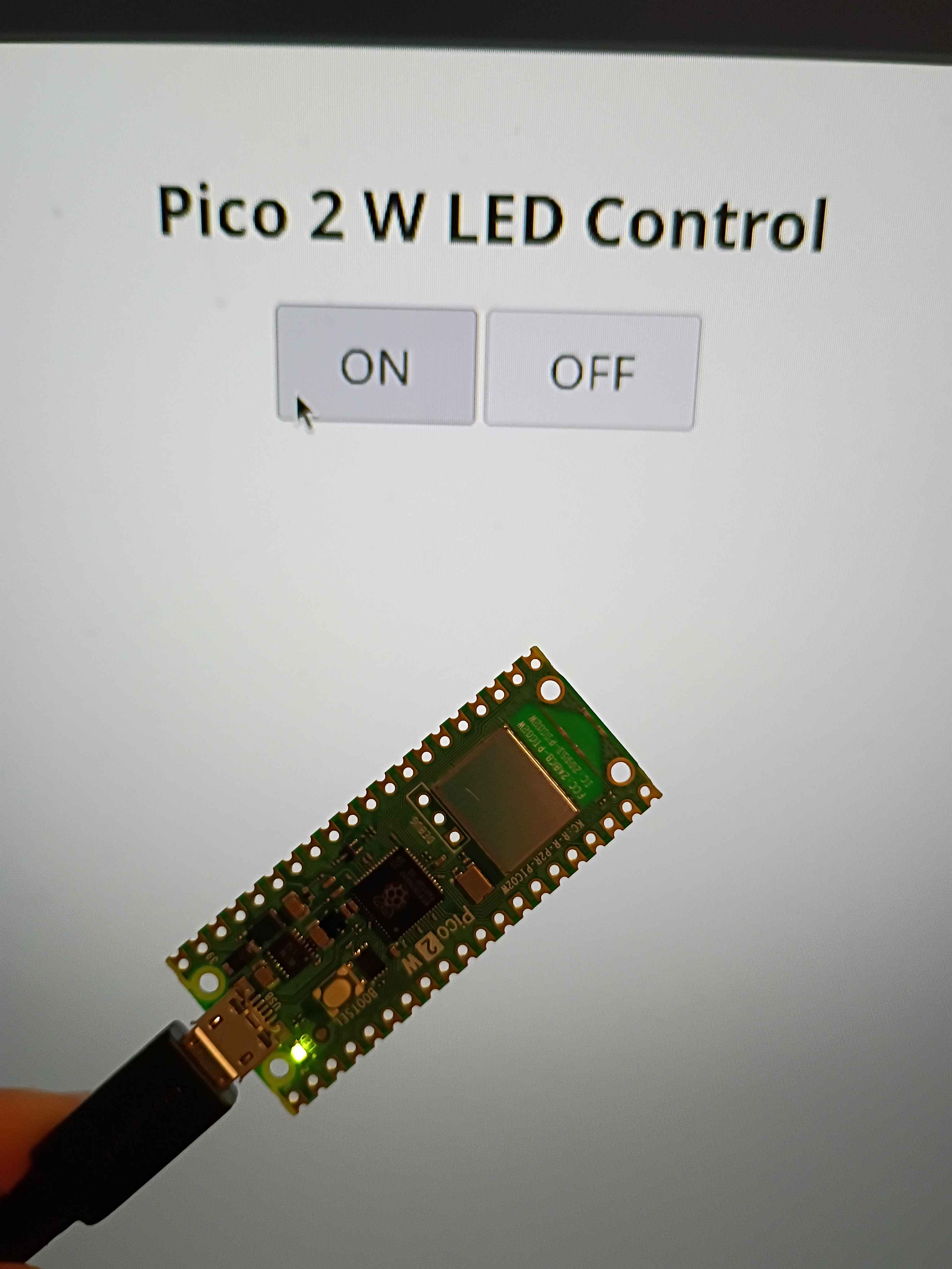
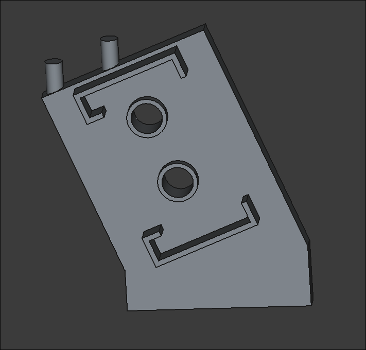
Finished all CAM programming for the 00003-002. Will cut at a time when I am allowed to make some noise. 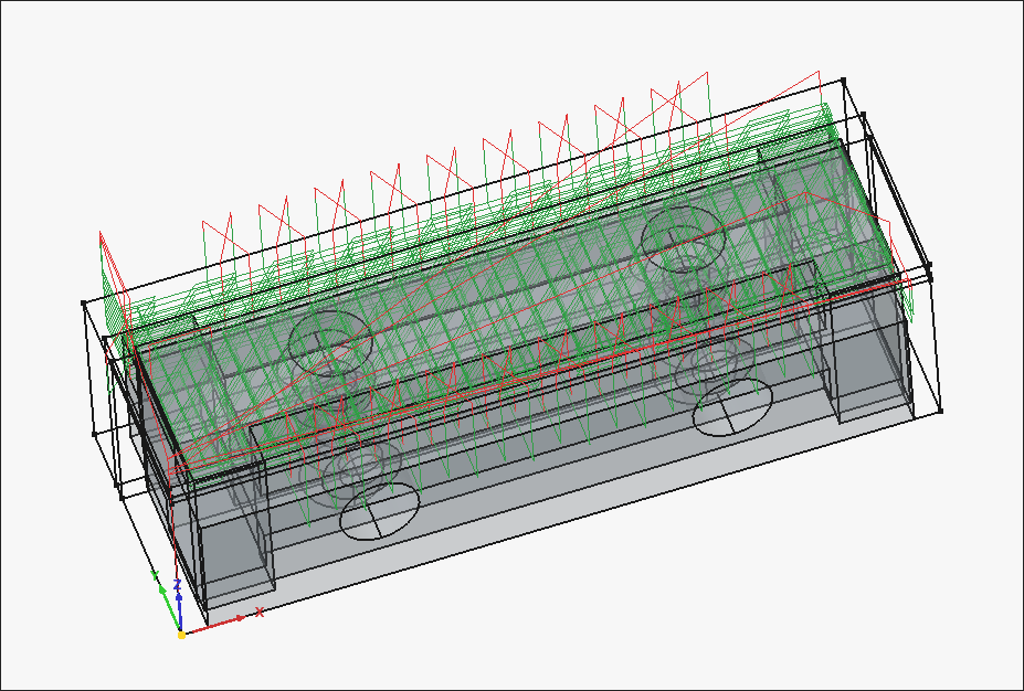
Working CAM paths for the 00003-002. After an hour of trial and failure regarding the "External" slot (on the right side of the image), I discovered that you can do a normal pocket operation by clicking the bottom face of that feature, and then going to "Extensions" and ticking "Enable Extensions" and "Extend Corners". I think the problem stemmed from the fact that the ledge was narrower than the bit diameter, but this cheat code seems to work. 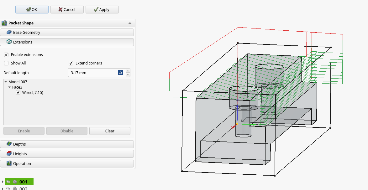
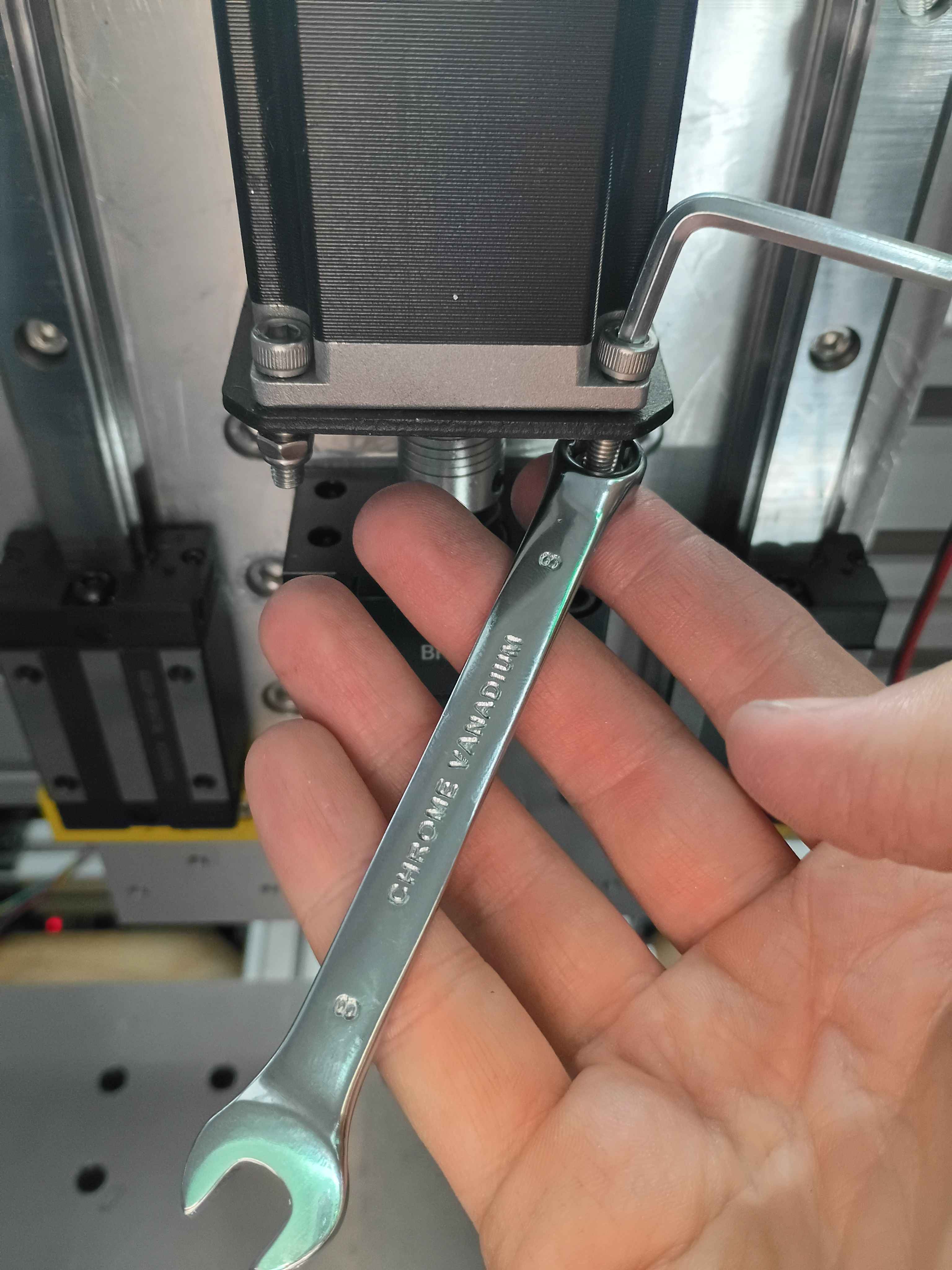
Machined the rest of the 00003-001 on the 00001 CNC prototype. Learned a lot about offsets and the controller. Some lessons learned about the FreeCAD CAM toolbox include oversizing the stock, even in XY if that does not represent the actual material, as this will allow you to be slightly off in zeroing the part, which will save time, since the edge finder takes forever to use. To remove collets from the spindle, after unscrewing, you can choke the collet with one of the wrenches and jam the other one in the gap between it and the spindle and twist, and any stuck collet will pop right off.
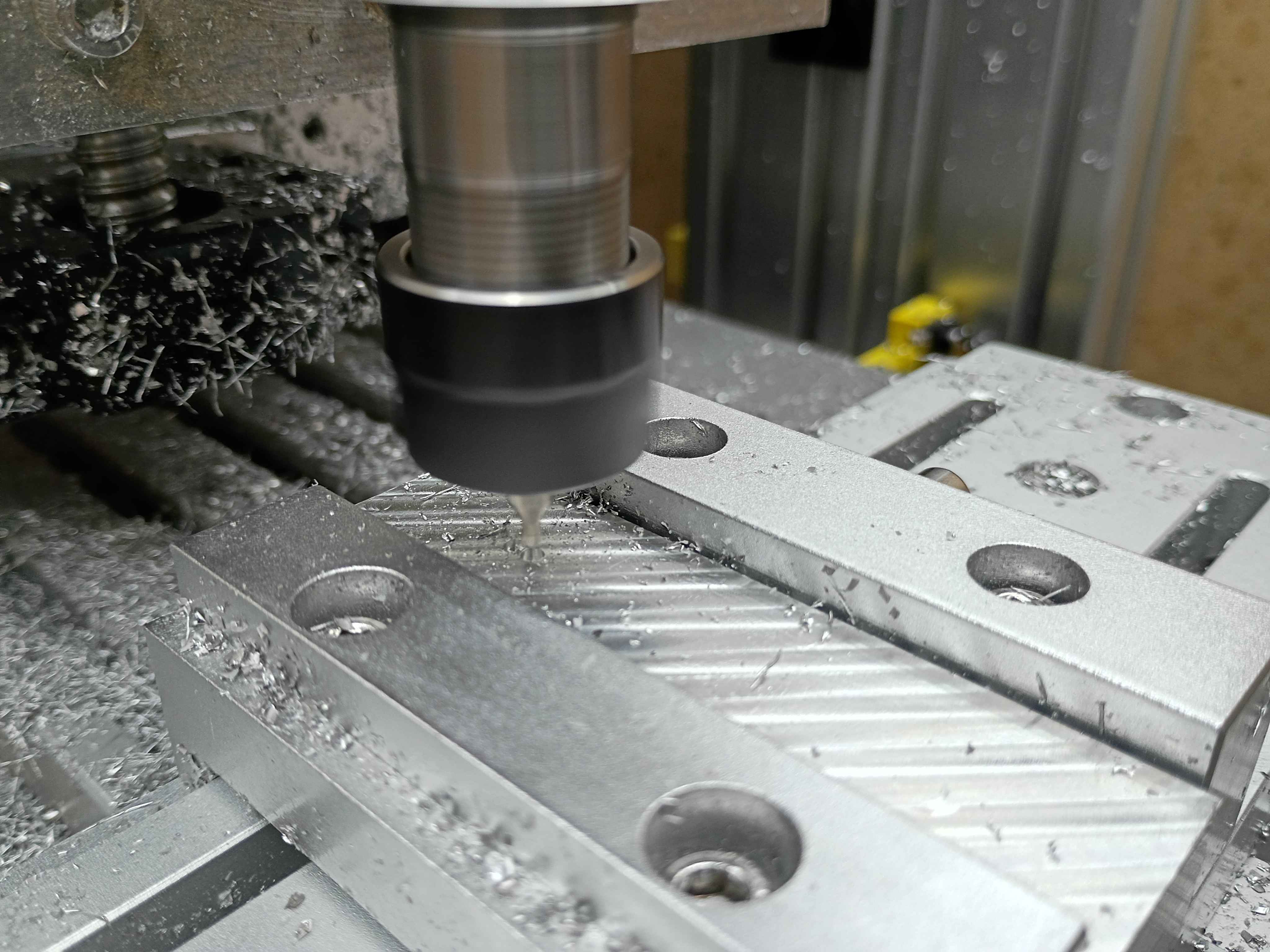
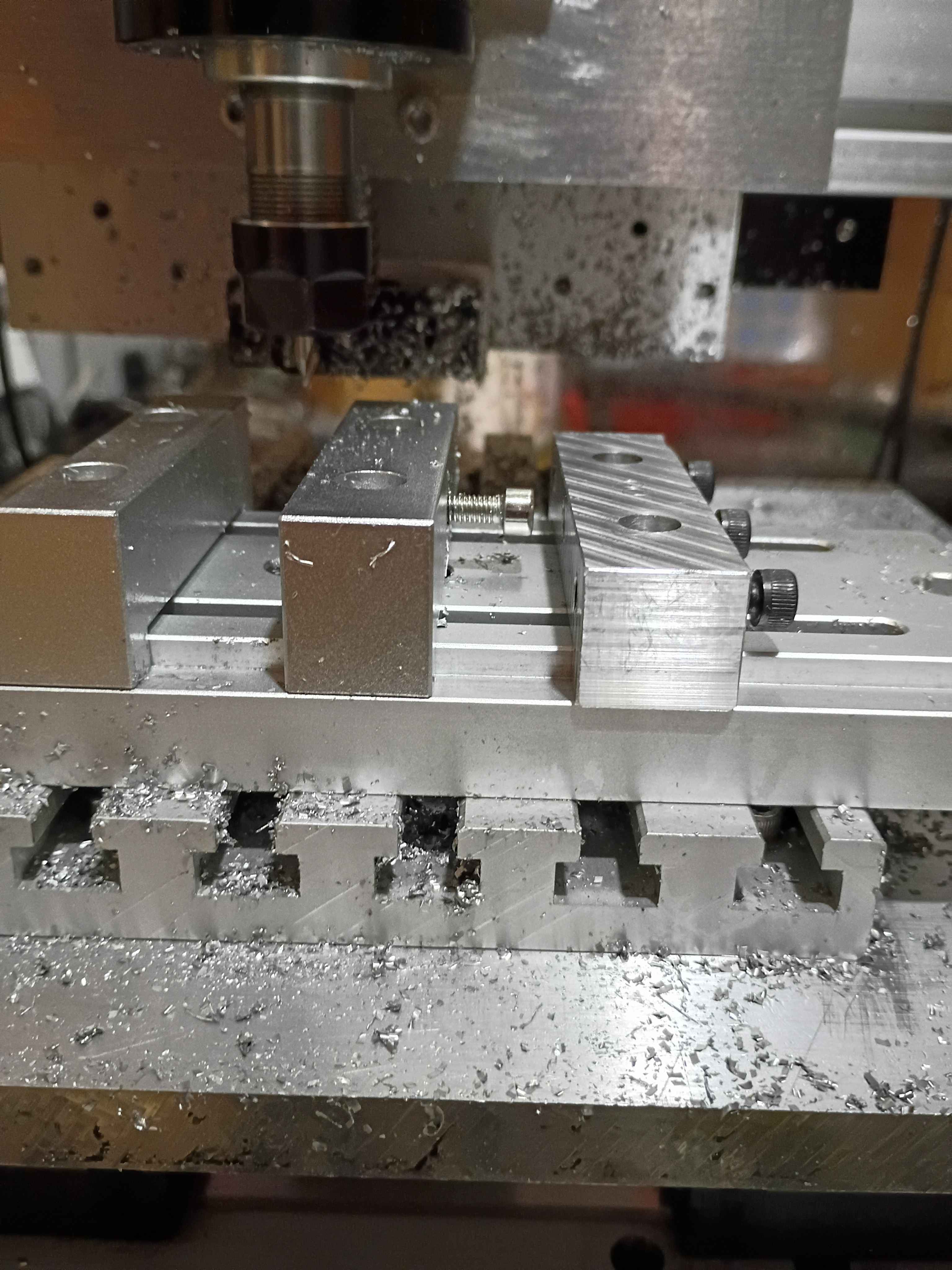
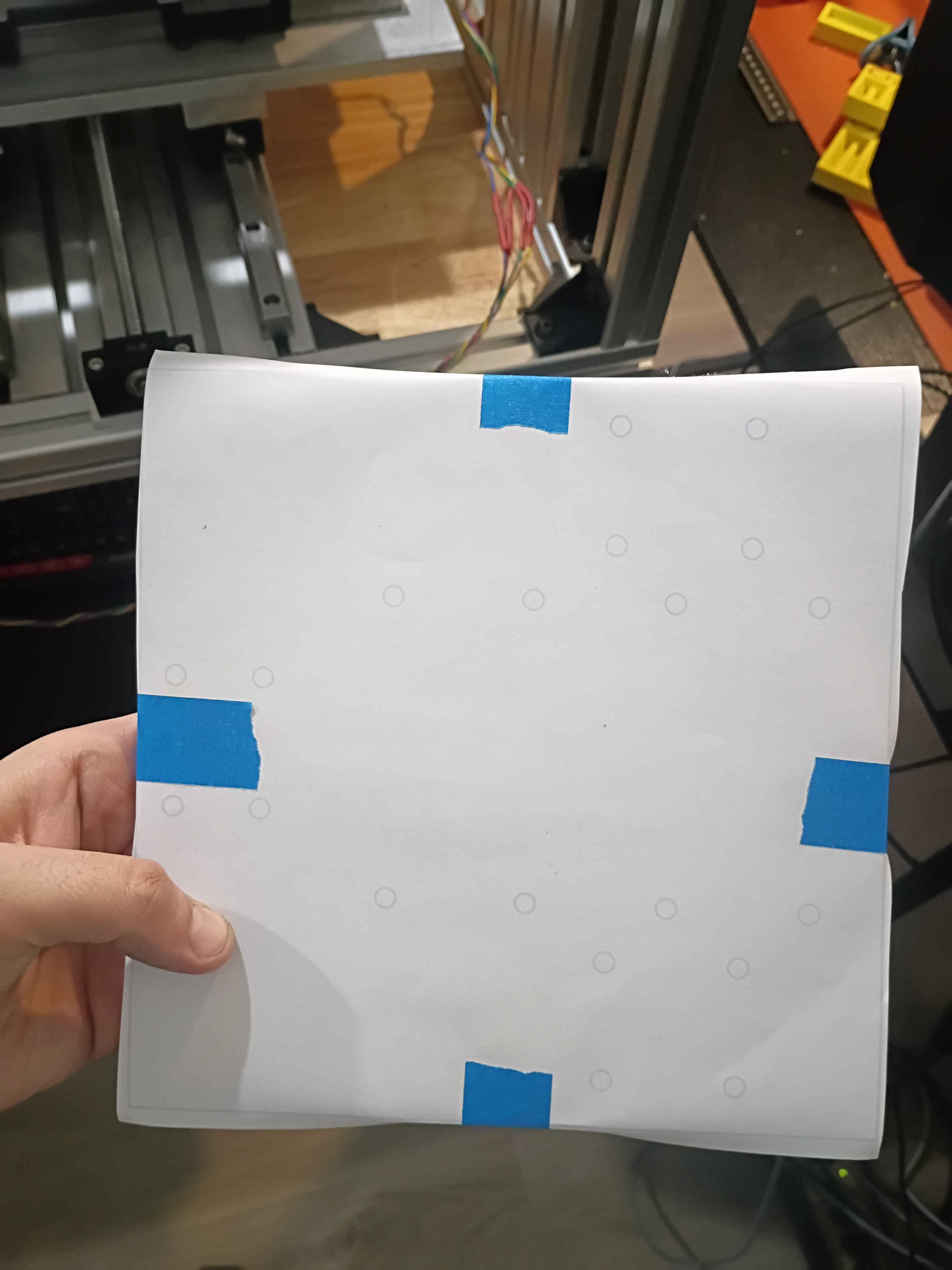
Used the CNC as a manual mill by jogging directly and inputting specific MDI Gcode commands to face certain areas and trim the long direction to size. Also use a tiny center drill on the CNC to precisely position all the holes, though I did drill manually on the drill press and tap by hand.
All in all, took a few hours to make this part, but a lot of that was the learning curve. The other parts are basically copies with some minor simplifications, so I will be sure to time how long those take to produce. 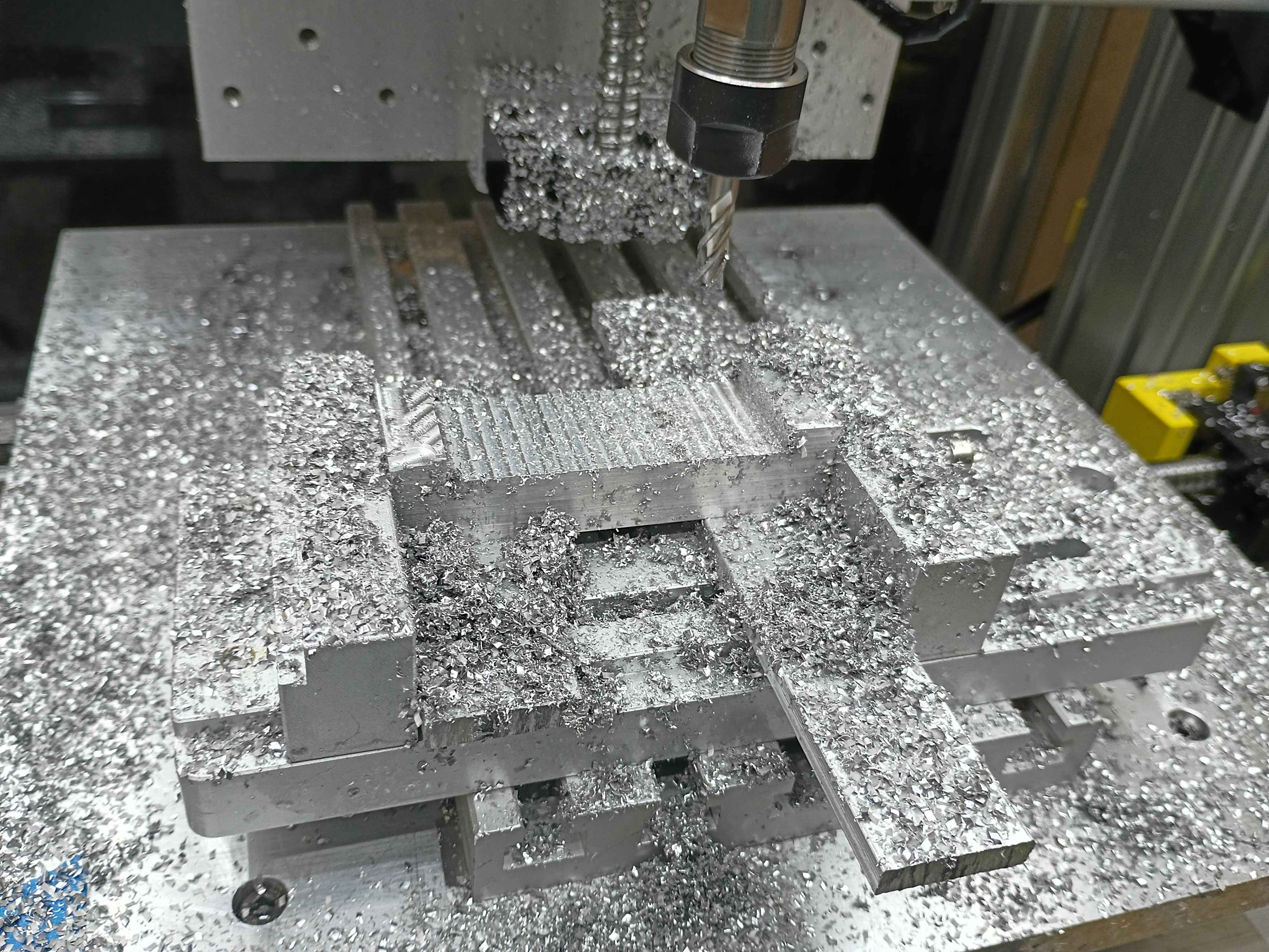
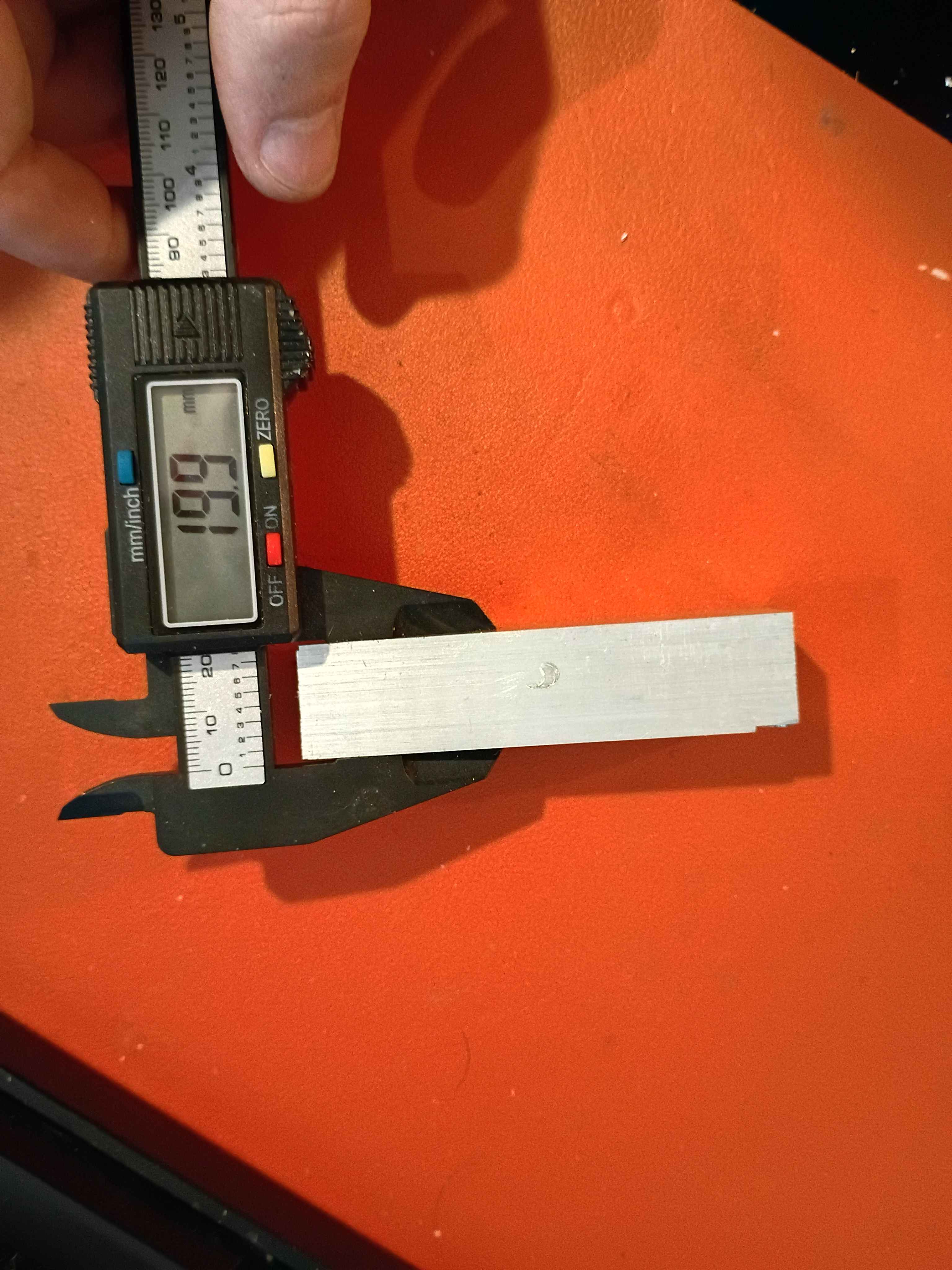
Got some experience with everything from coordinate systems to speeds/feeds, to the Mach3 controller. Faced the top and bottom surfaces to 20mm thickness within .2mm for the 00003-001. Tiny oopsie on the corner (bottom right of second picture), though that should not detract from the function. See video. All good fun. 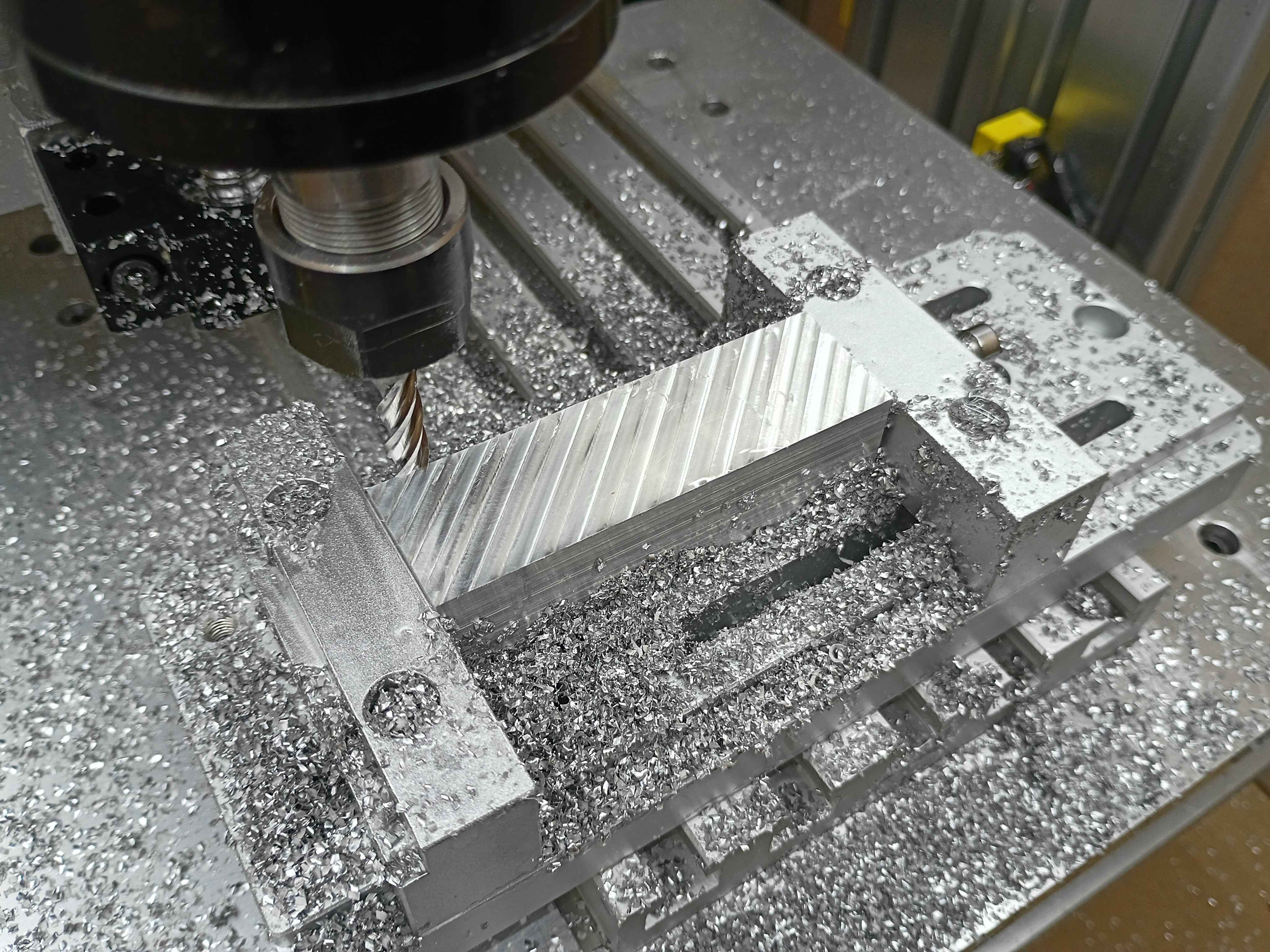
Added 60sec timed pump control button to the web UI. That's roughly half the bucket per pump. 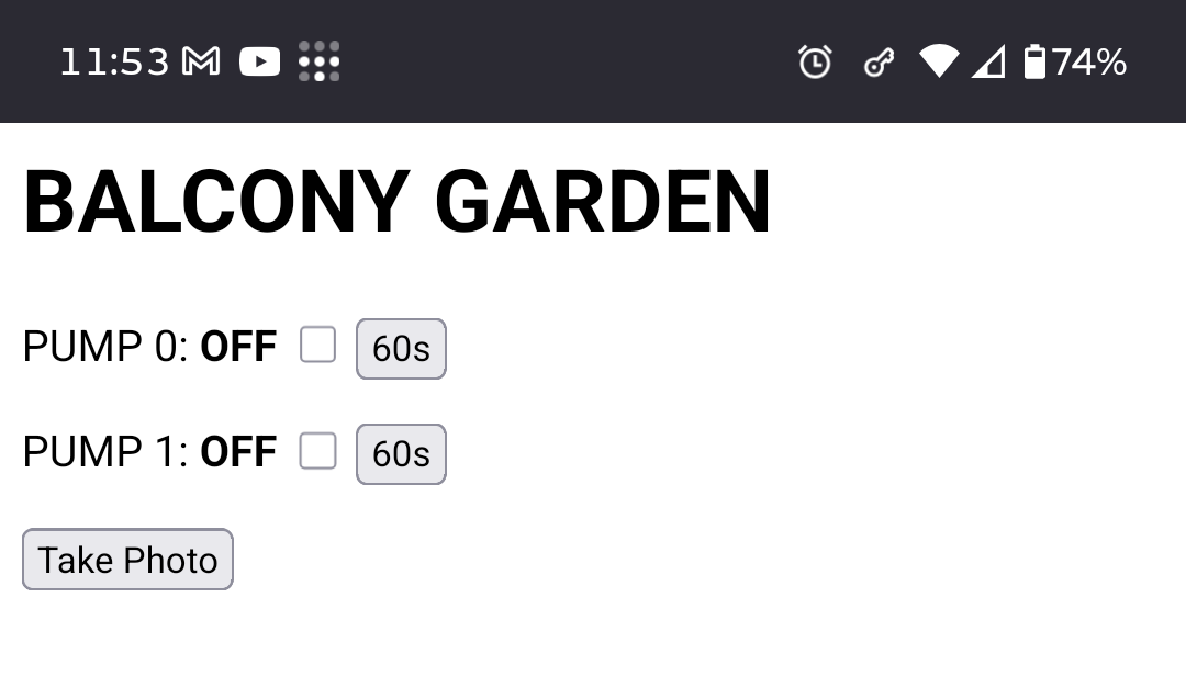
Learning more about the CAM workbench. 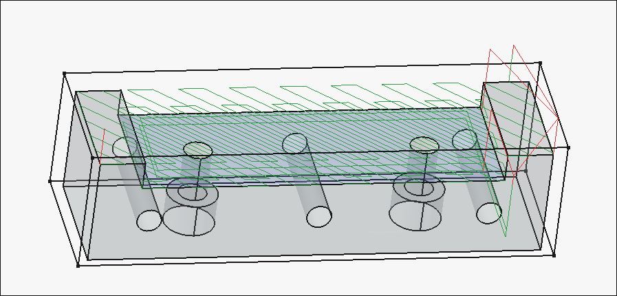
Working on the cnc toolpaths. 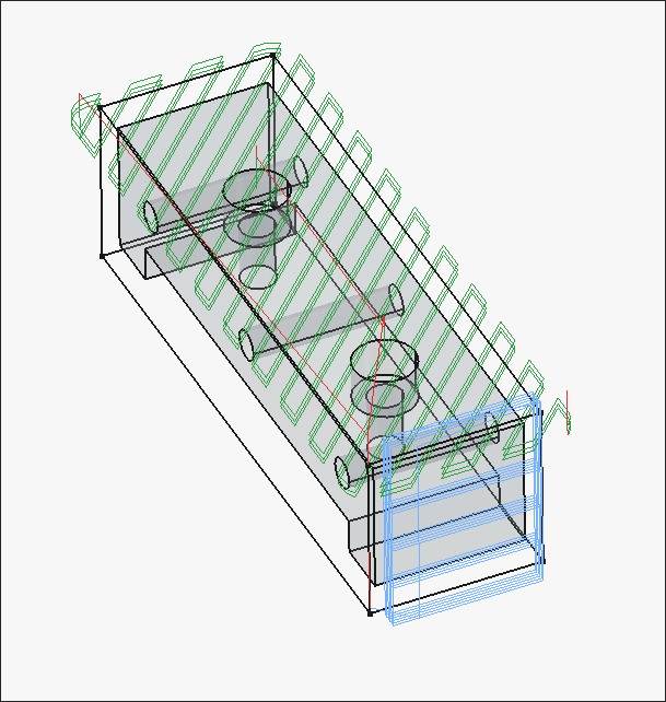
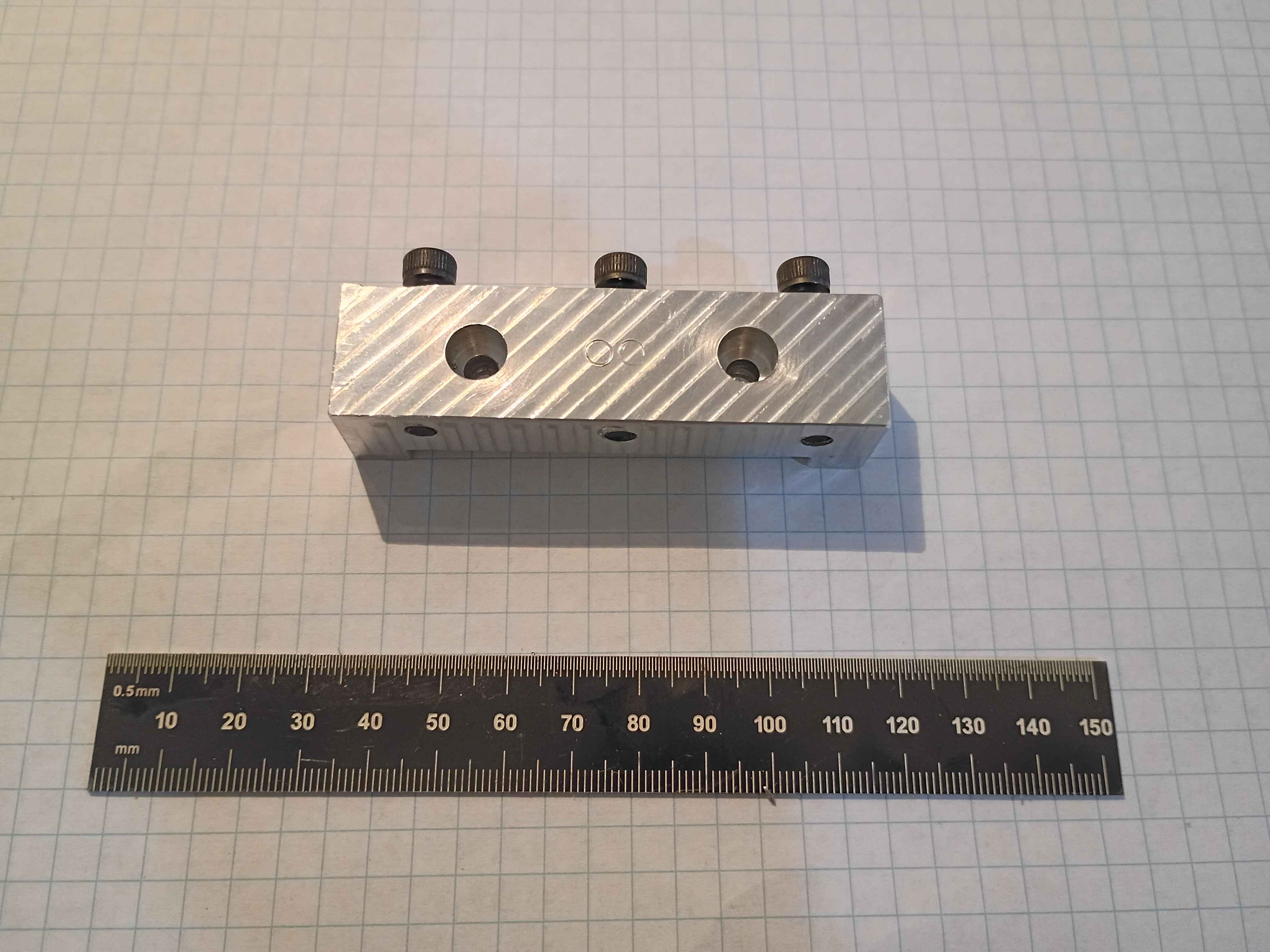
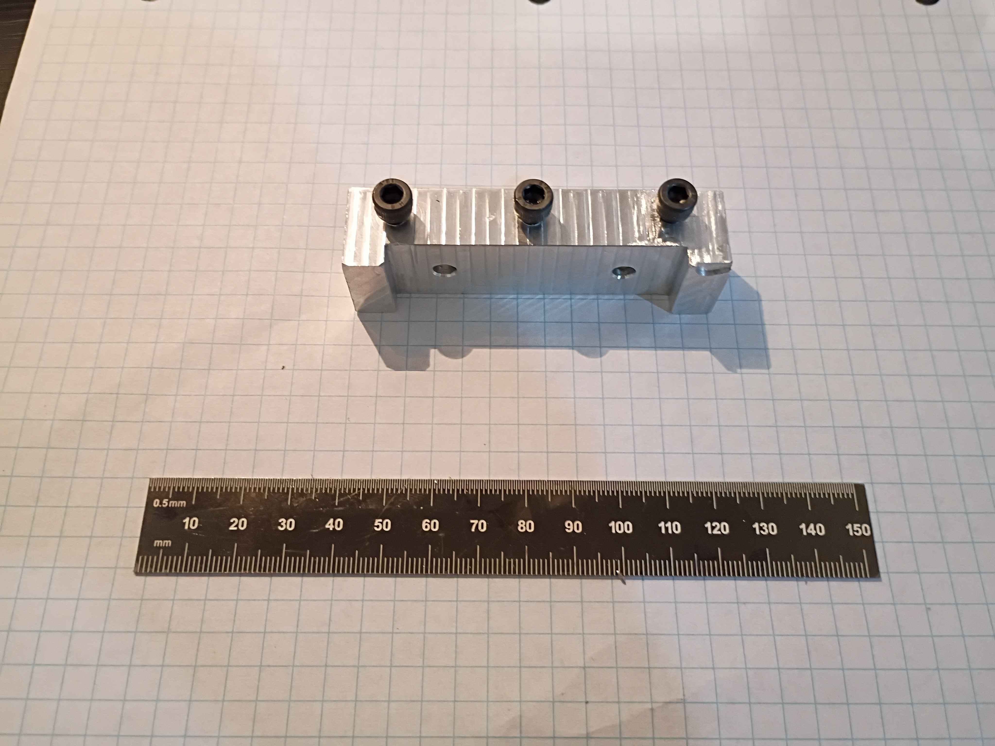
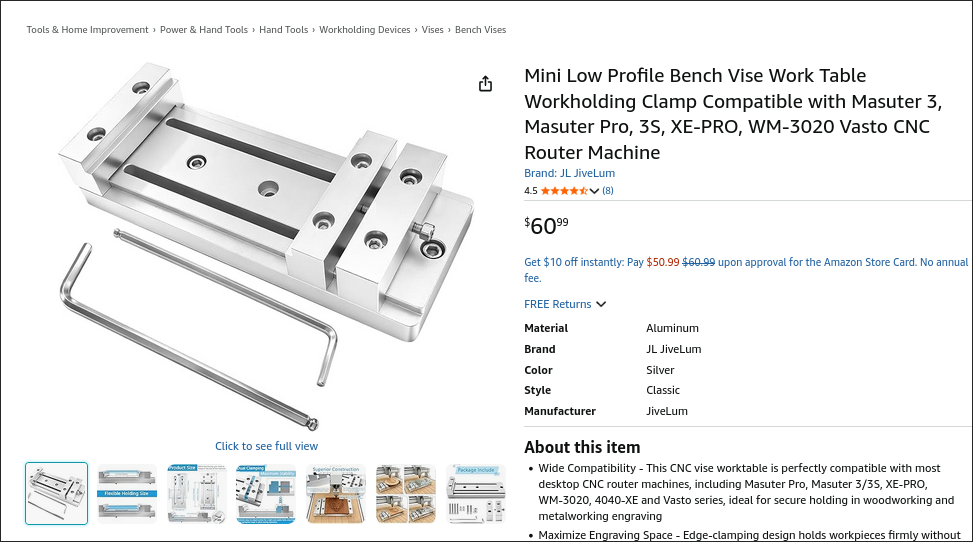
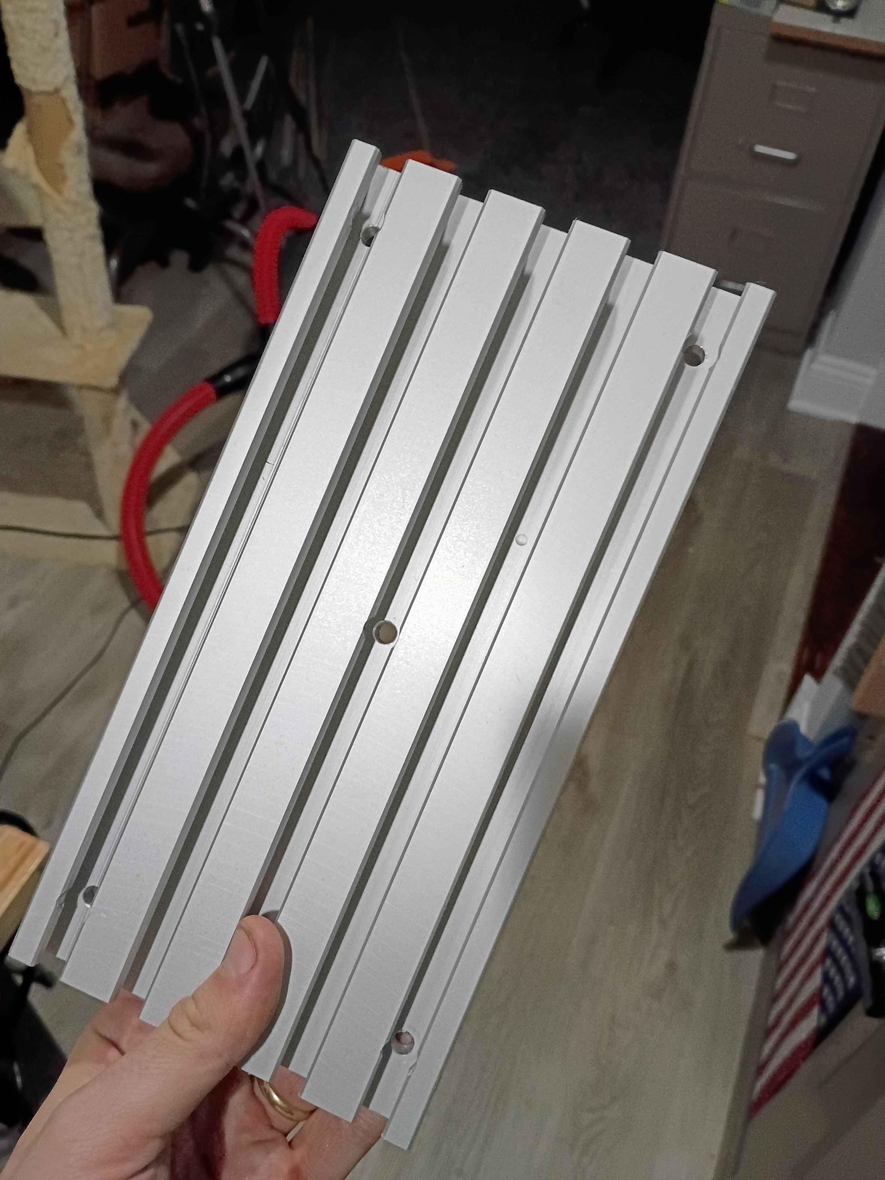
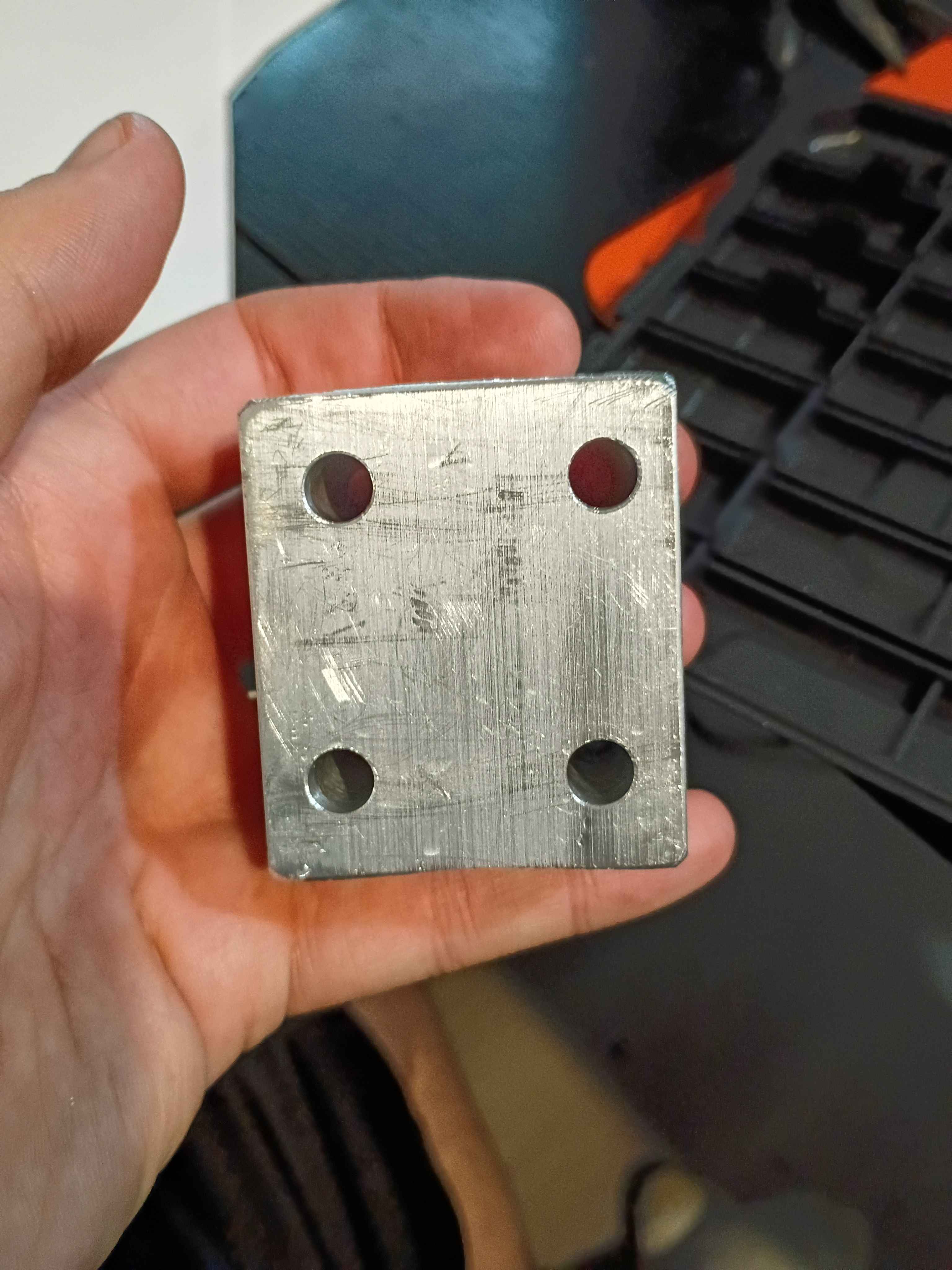
Modeled the 3 distinct parts of the low-profile vise. It's based on this product on Amazon. It has a bolt pattern than more closely matches the T-slot spacing on the 00001 CNC prototype, is sized for standard (cheaper) imperial material stock thicknesses, has more horizontal threaded holes for clamp-up, thru threaded holes for the side clamp pieces, and lower-profile clamp pieces that should provide adequate clearance for the entire y-axis of the 00001 CNC prototype to move without crashing into the vise. The 00003-003 large lower slotted piece can also potentially be made thinner to reduce cost and improve clearance. The 1x -001 and 2x-002 pieces will be machined on the 00001 CNC from aluminum to replace the stock ones on the product purchased from Amazon as a first preliminary test of cutting aluminum. Added the assembly to the repository. 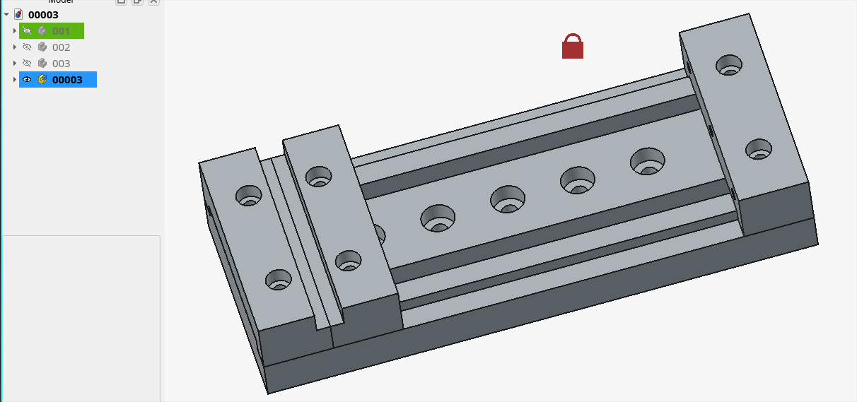
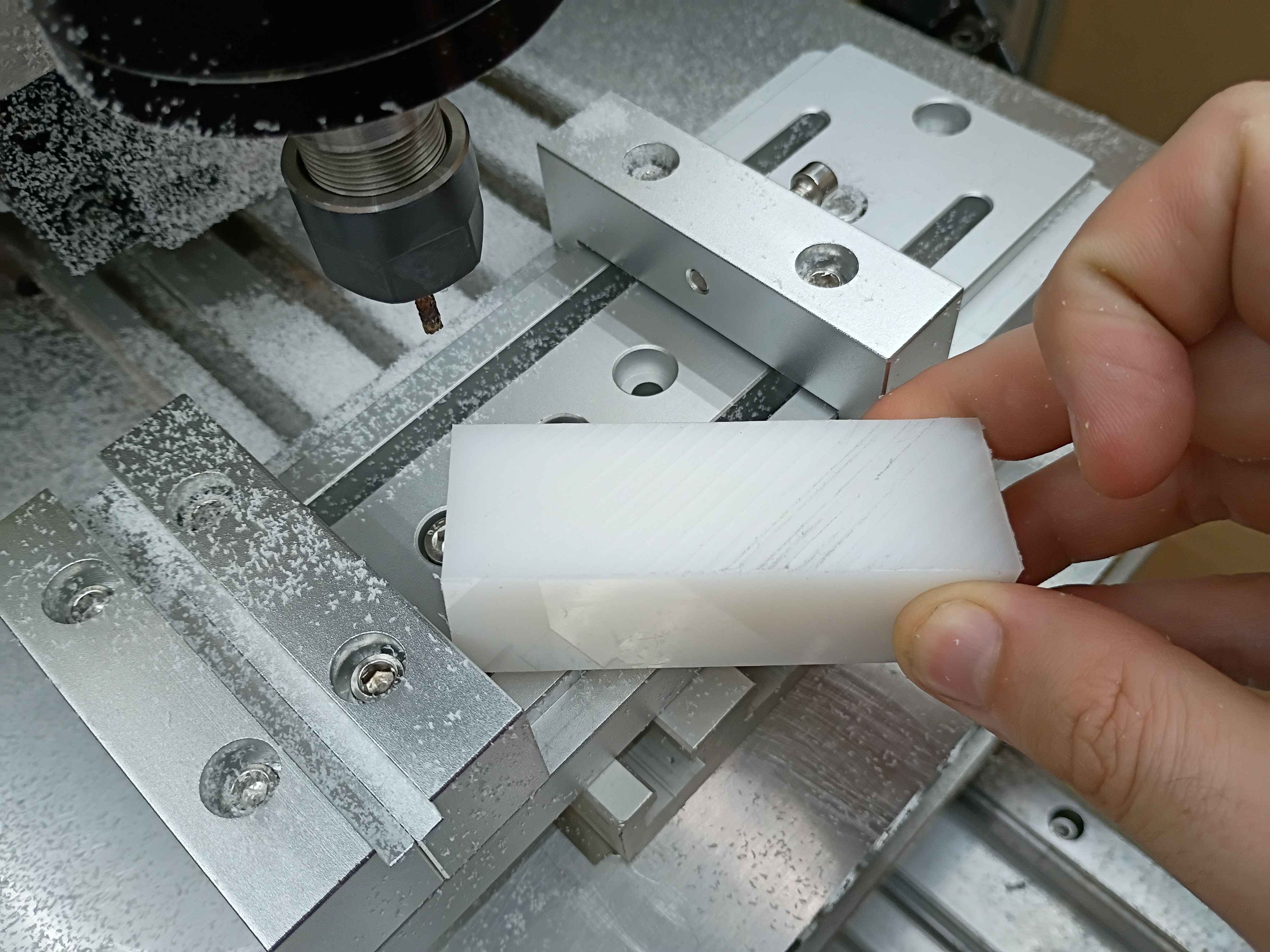
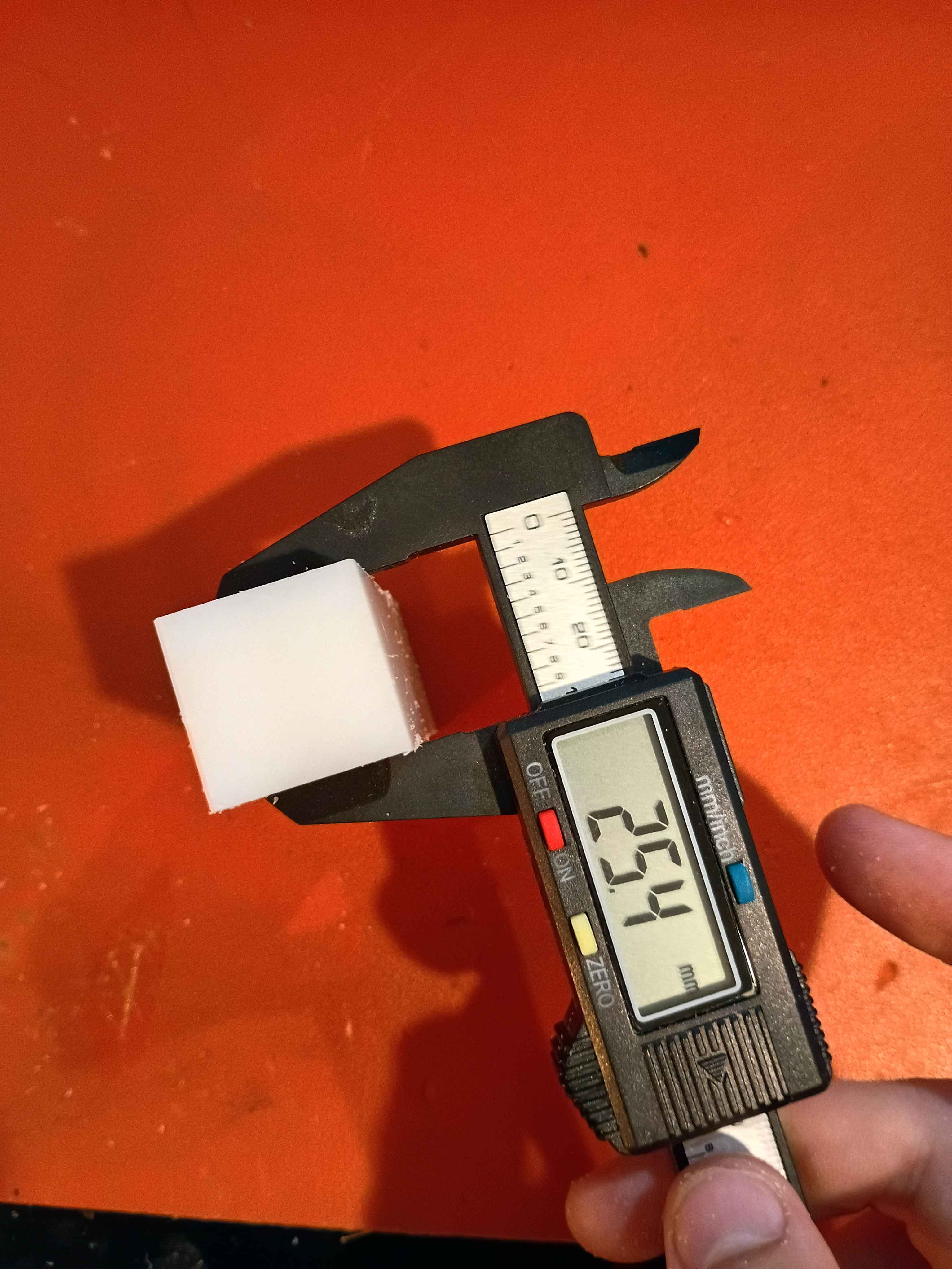
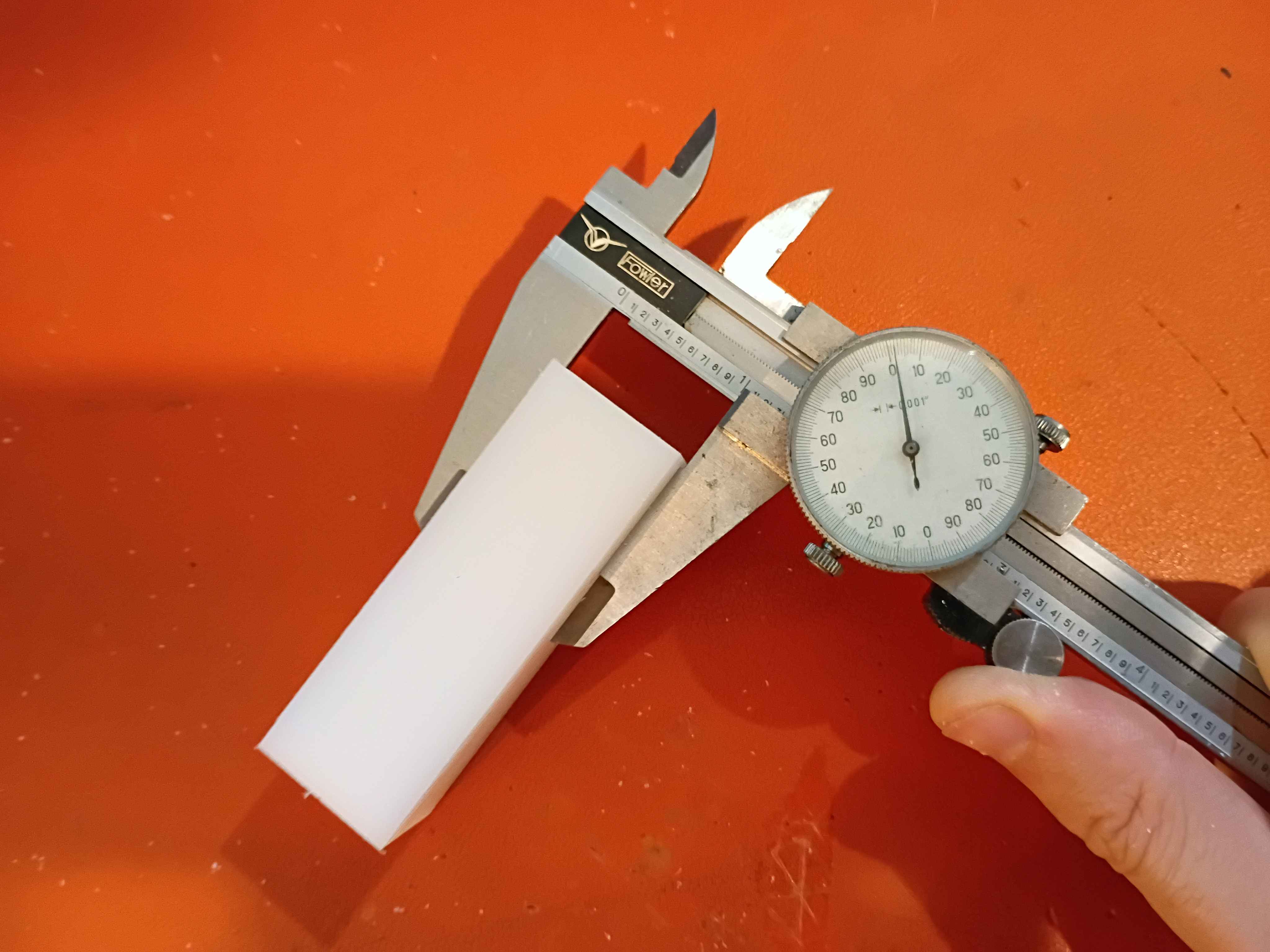
Realized that there is a fundamental flaw in the setup that completely disqualifies a large portion of the y-axis (long axis). There are a couple bandaid fix options for it, and the best are to just drop the vice onto the gantry plate, reduce the Z axis ballscrew length, or just avoid large swaths of the milling volume. Was able to face the top of a 1x1x3" piece of HDPE within .001 (although that's more a measure of how well I was able to guestimate Z-zero position of the top of the material. The total variation across the part was .000 to .002. It cut well but produced a lot of HDPE dust because I was using a PCB drill instead of an endmill for fear of breaking something more valuable on the first real milling attempt. I was cutting a 30 mm/min and 100 Hz with a 1/8" PCB drill, which corresponds to around 5000RPM. I learned a lot about how to use the MachCNC software. See video. 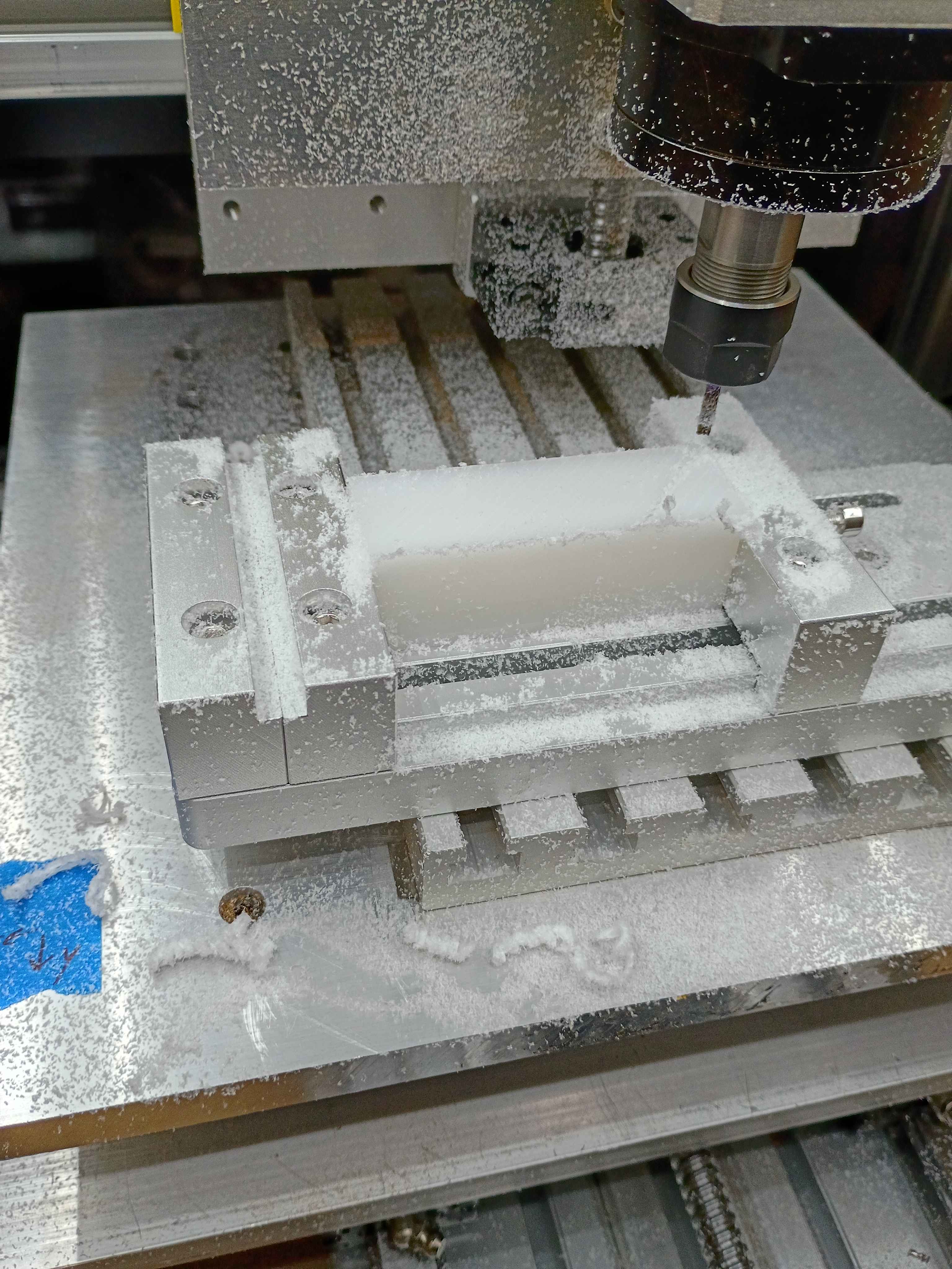
Added some functionality to the server to allow remote control of the pumps. 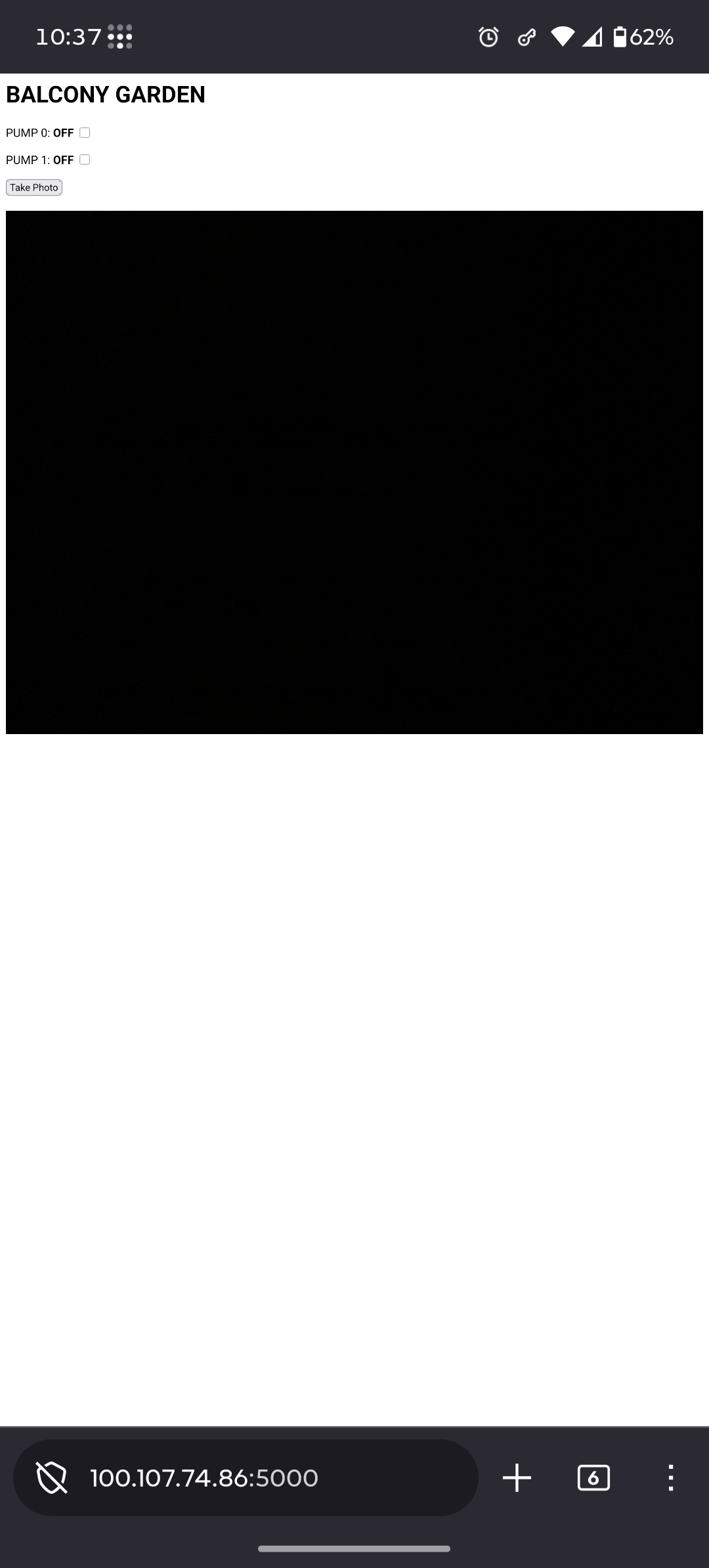
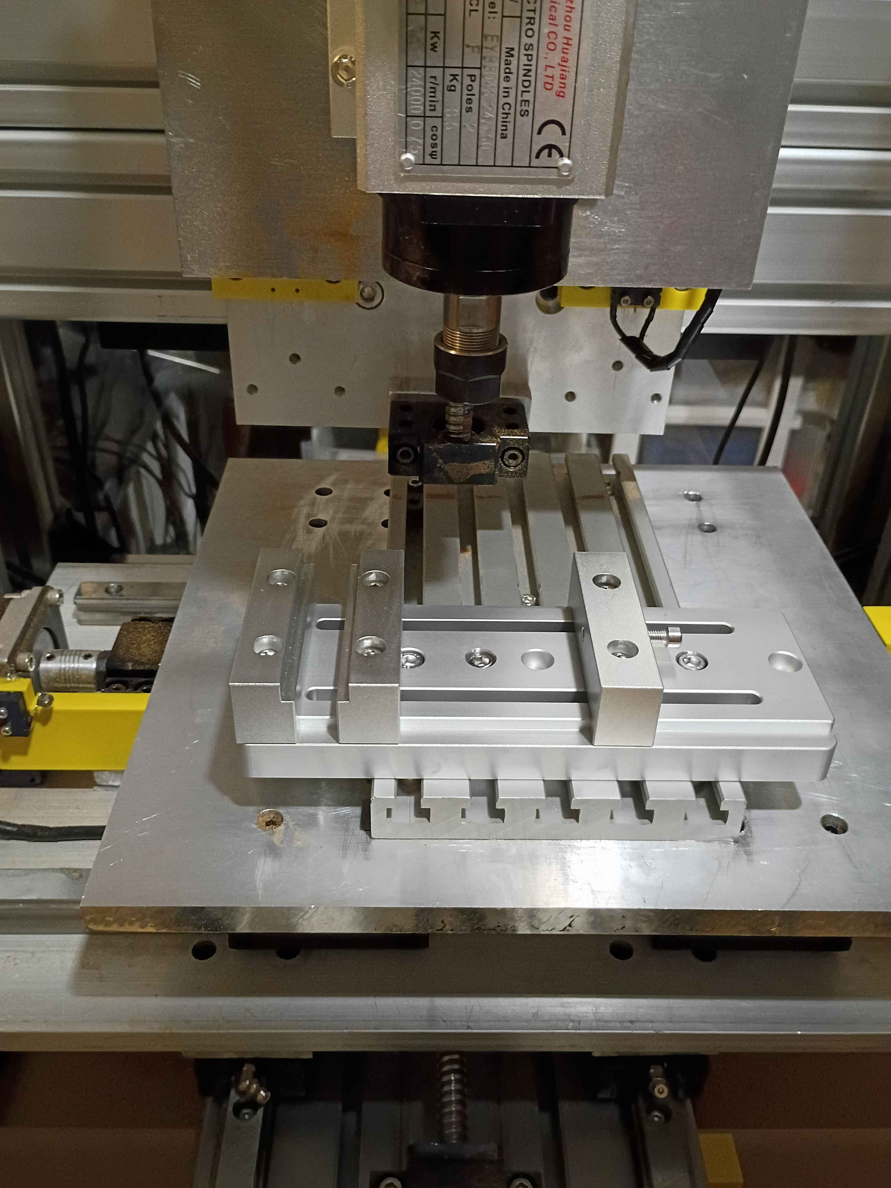
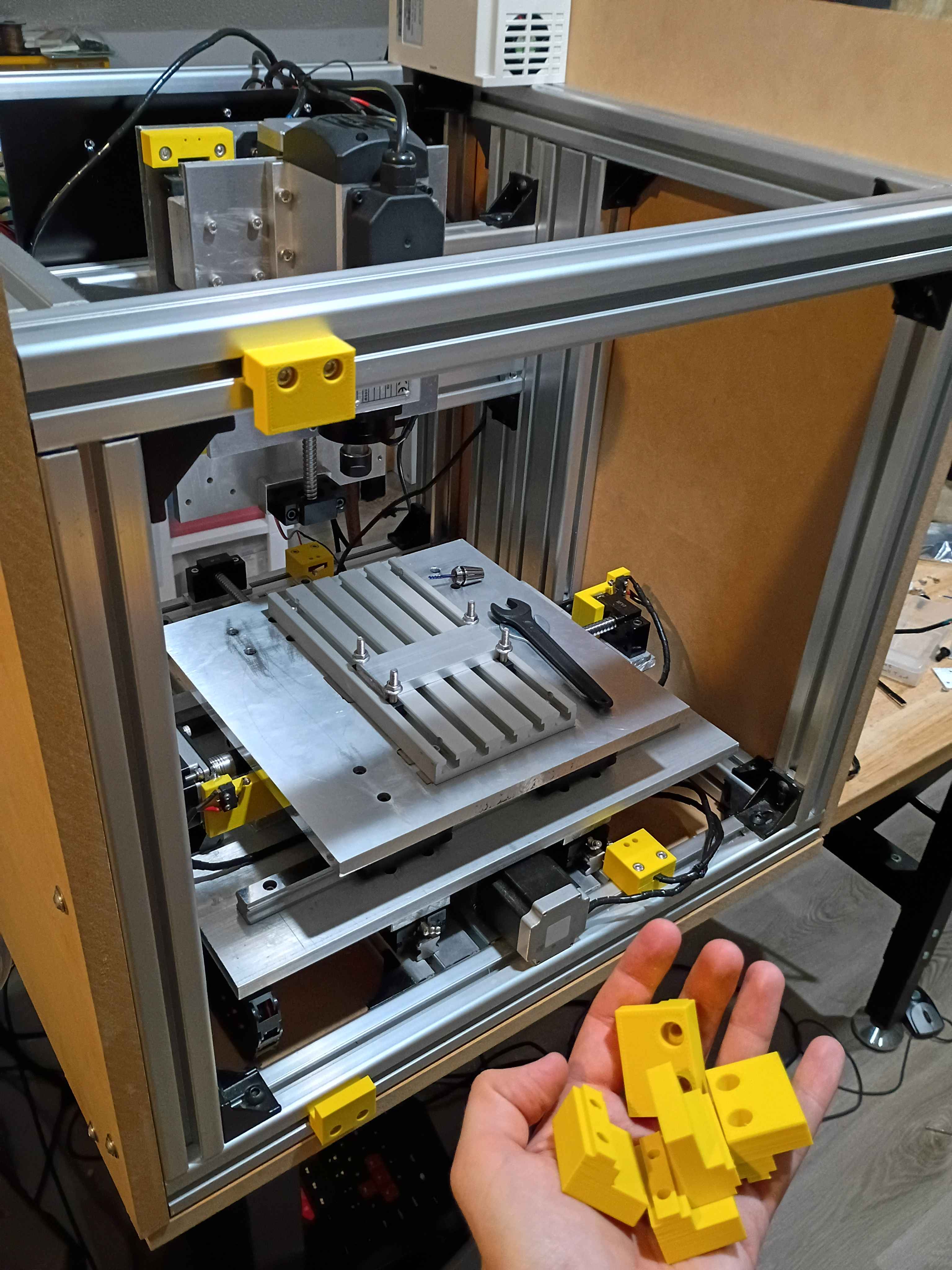
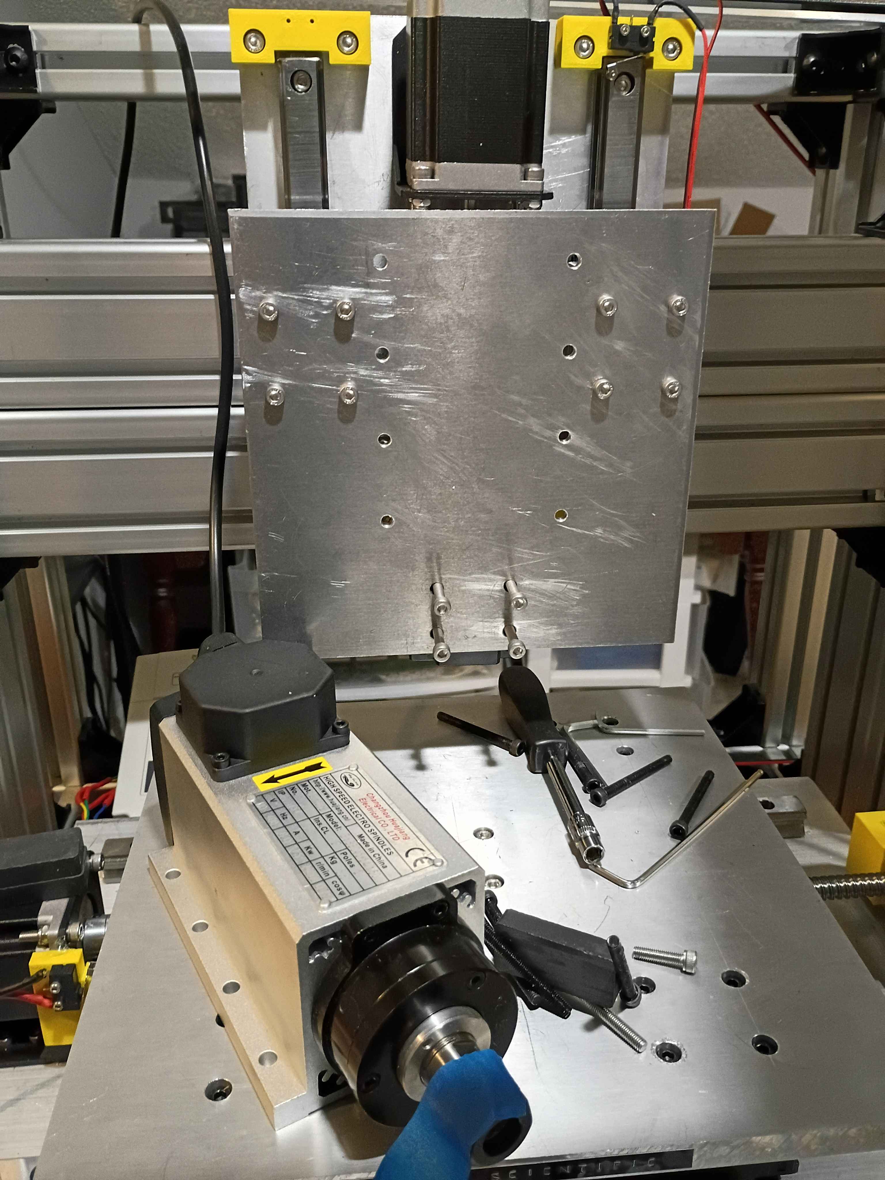
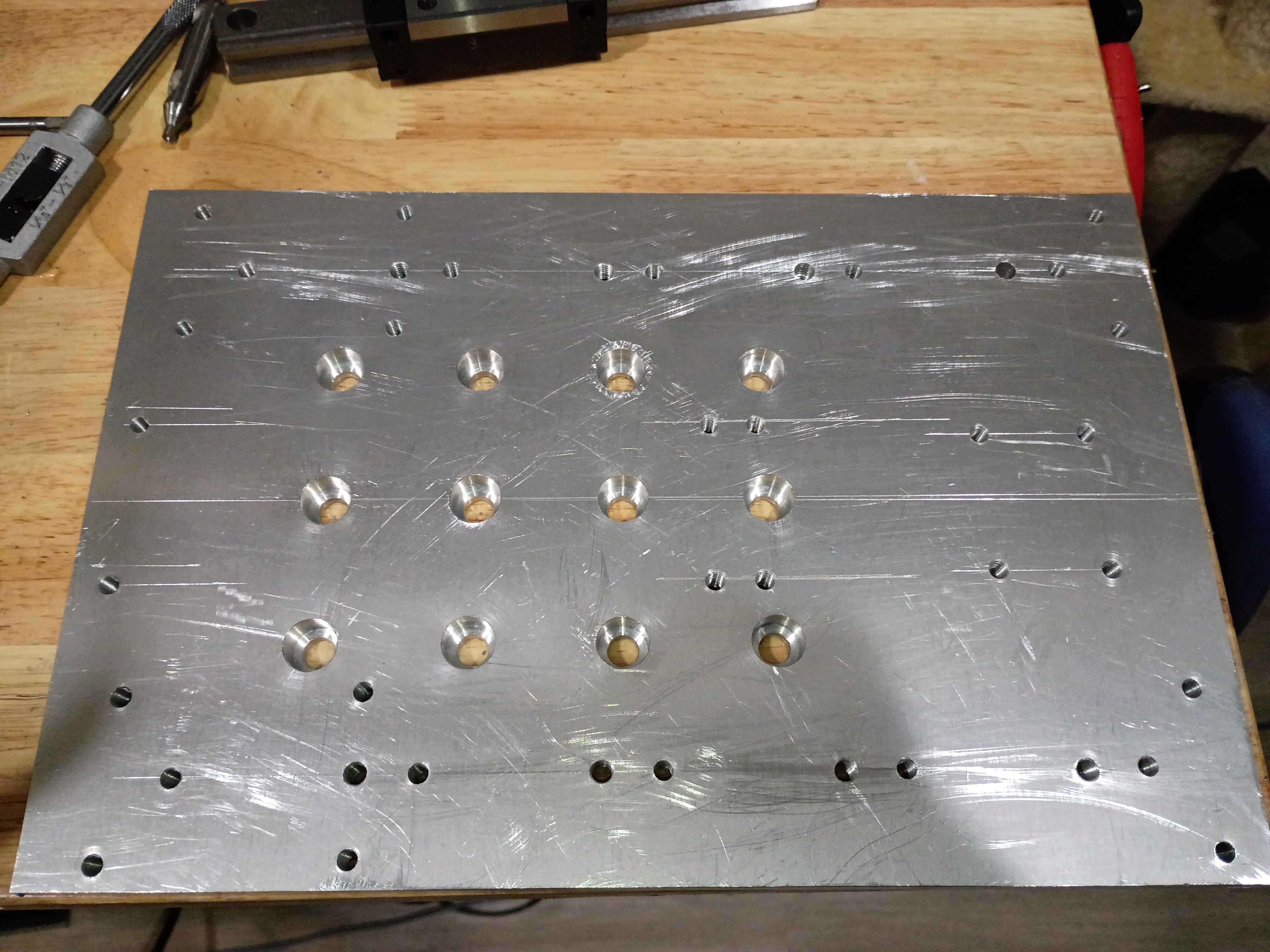
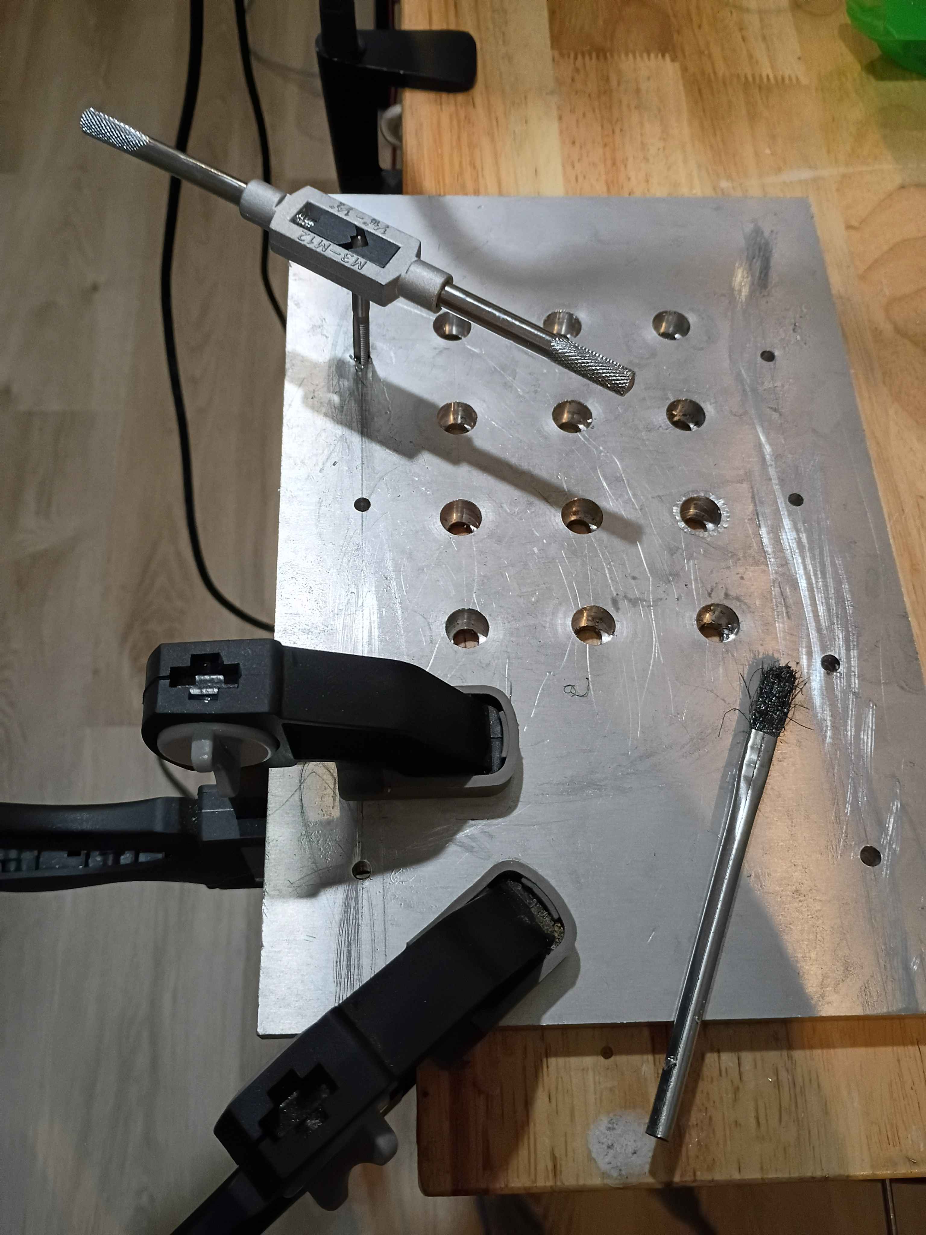
Received and mounted new 8A 12V power supply for the lights, which makes them way brighter, not overheat the power supply, not flicker out occasionally, and not dim the lights when turning on the fans. Also received the new machining vice and drilled (and counterbored) 3 new holes with a 1" spacing. Mounted up everything successfully, and ready for a test run tomorrow. The only caveat is that technically the vice is able to run into some of the z-axis components if the user is not careful, so that is a design flaw in the entire z axis setup. 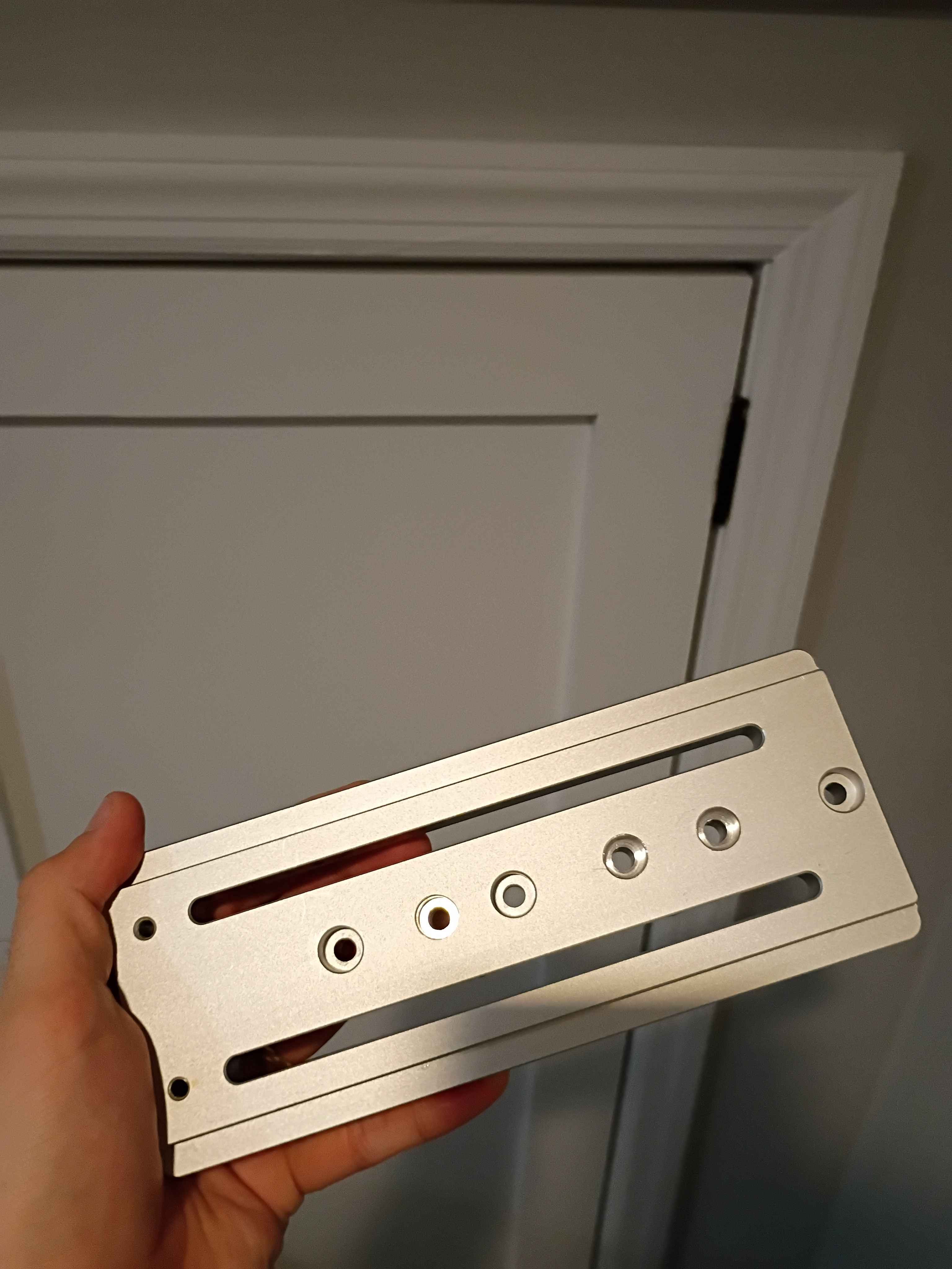
Wired up everything and successfully tested the 2 pump systems. It's not pretty, but it works. Also hooked up all the irrigation lines and staked them into the various pots in the dirt. Now only the software and container/camera mount remains. 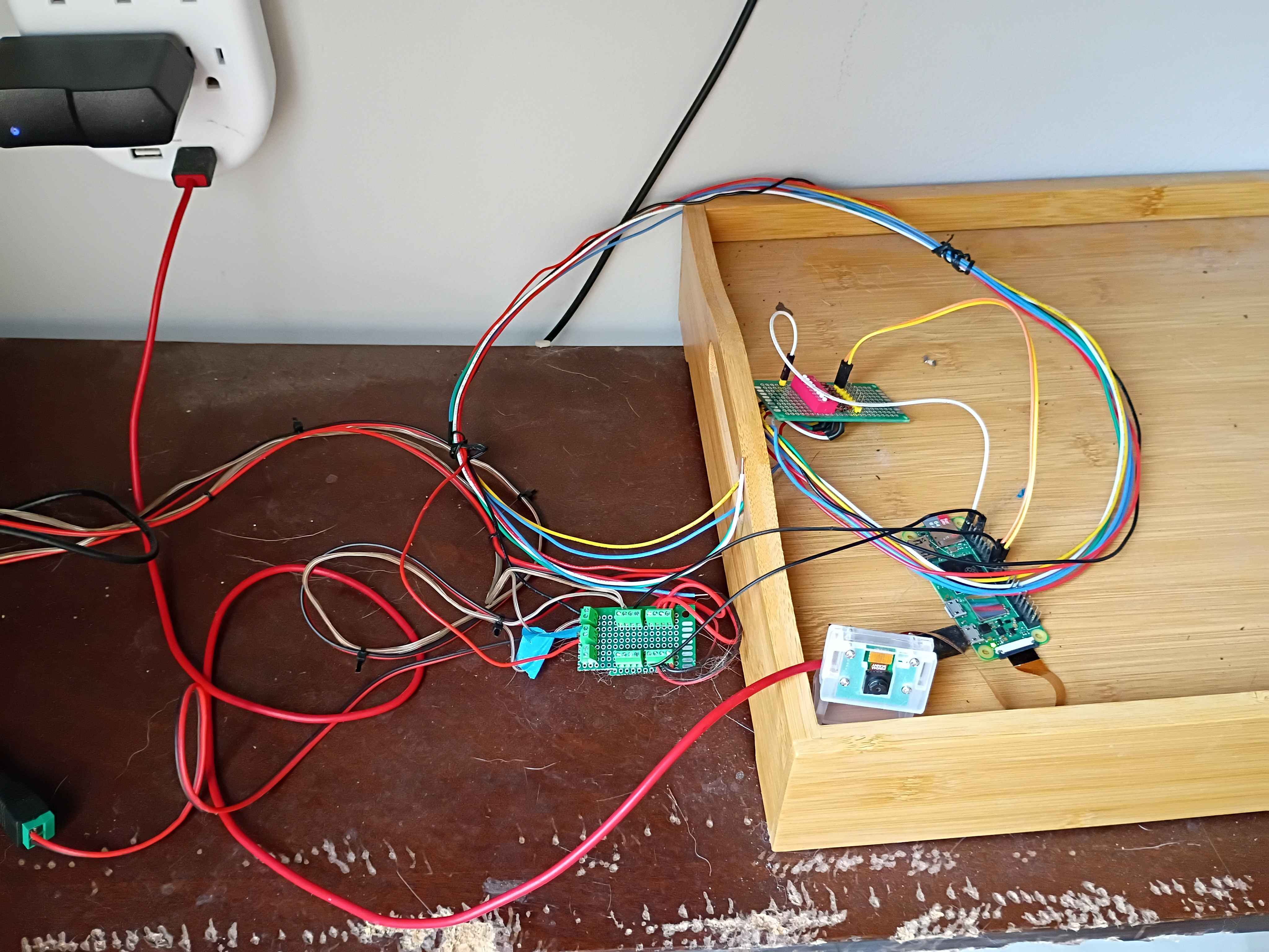
Rewired the control circuitry and pump lines, setting everything outside for a test run tomorrow. Using large coffee mugs to weigh down the pump inlet tubing. Soldered some screw terminals to a small breadboard to make removable connections between the Pi and the relays. 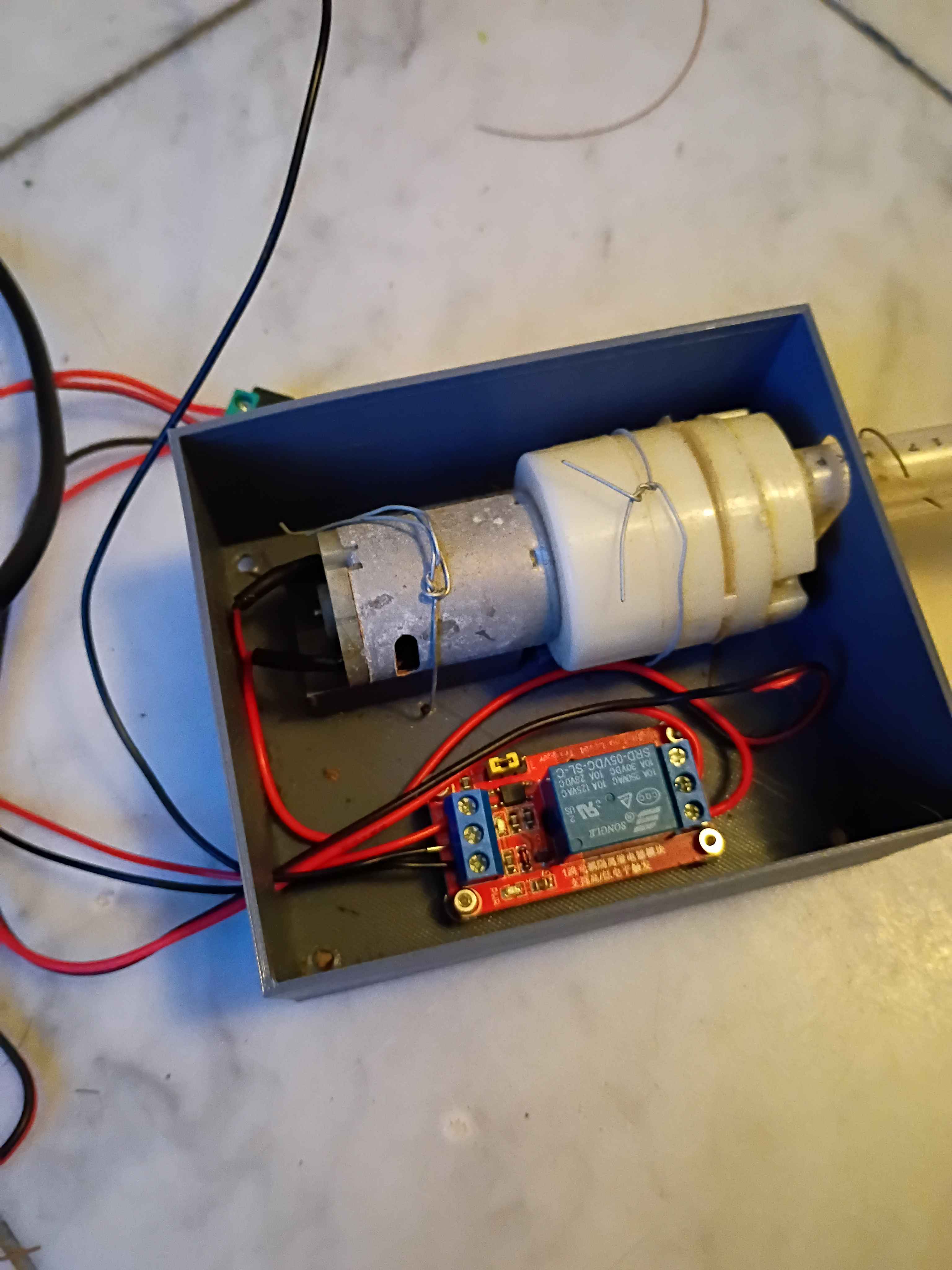
Determined Z-axis range of motion and purchased a clamp that allows for most of the use of the range, though it will require some extra mounting holes drilled into it. Also purchased some bellows to protect the ballscrews. 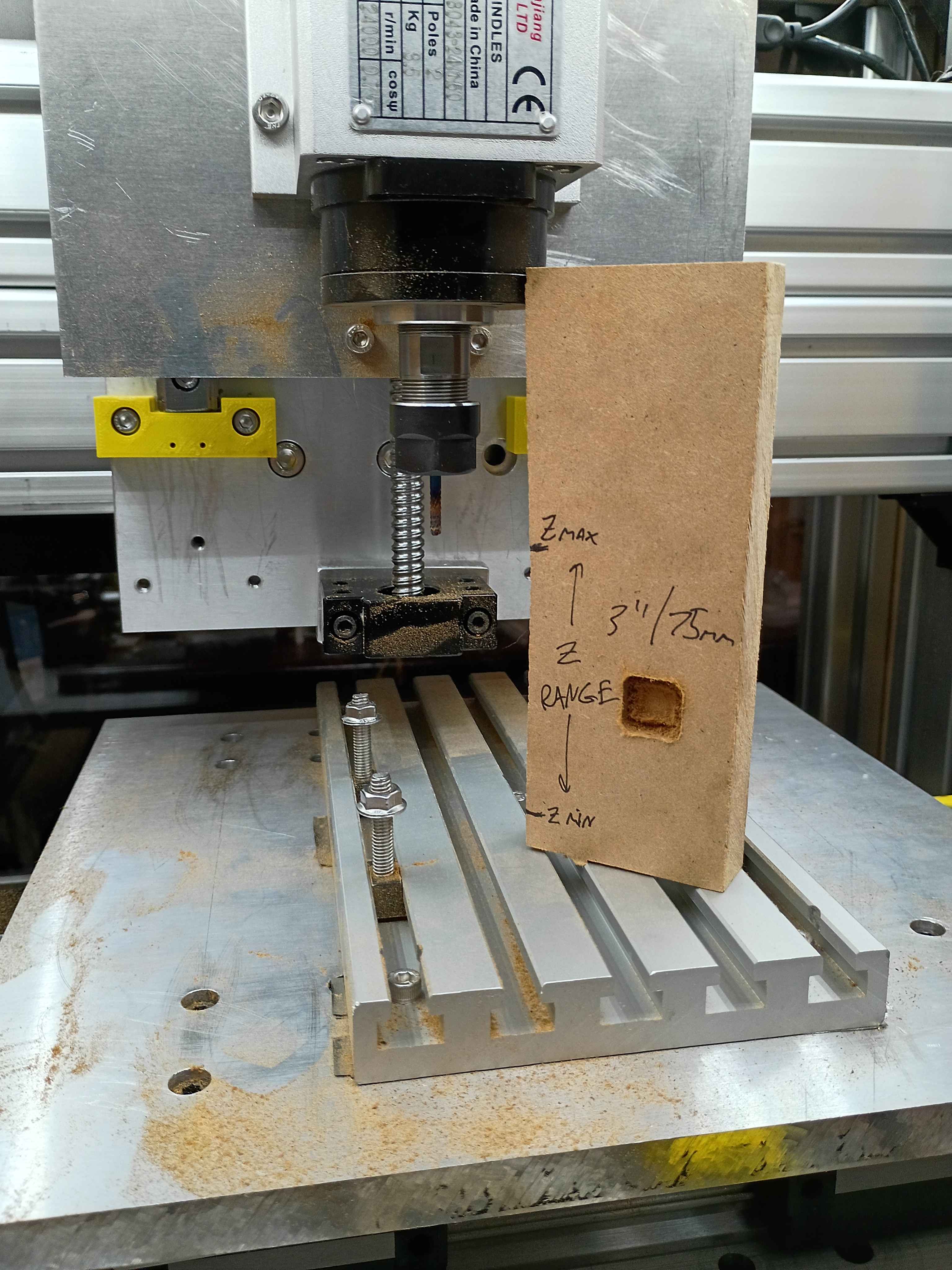
Conducted more tests on the CNC. Depth does seem to work properly, except that I run out of travel downwards in some situations. Can possibly be resolved with different fixturing setup. Also realized the 12V power supply I had on hand does not provide enough amps for 3 fans and the lighting in parallel. Ordered a more powerful replacement. 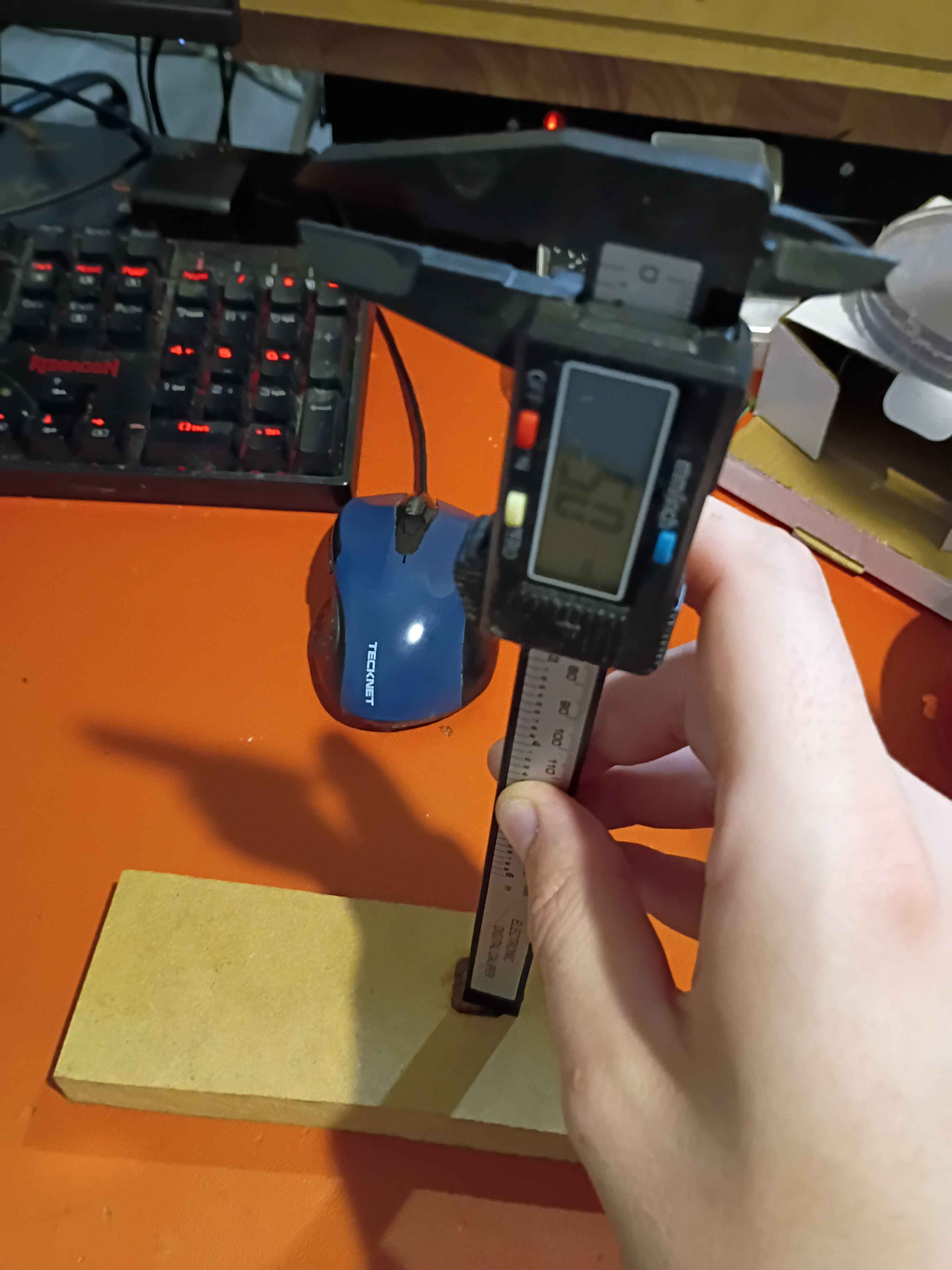
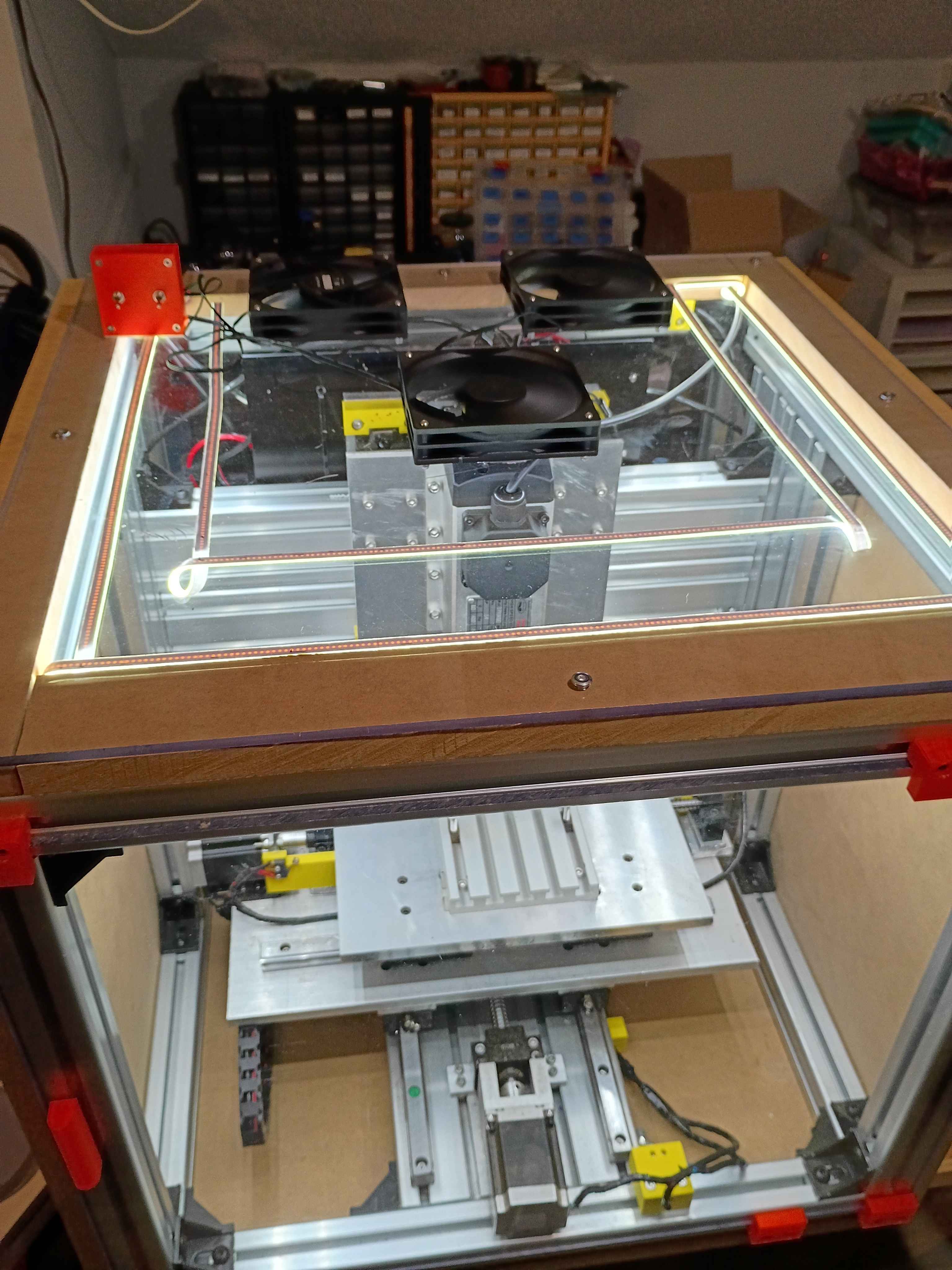
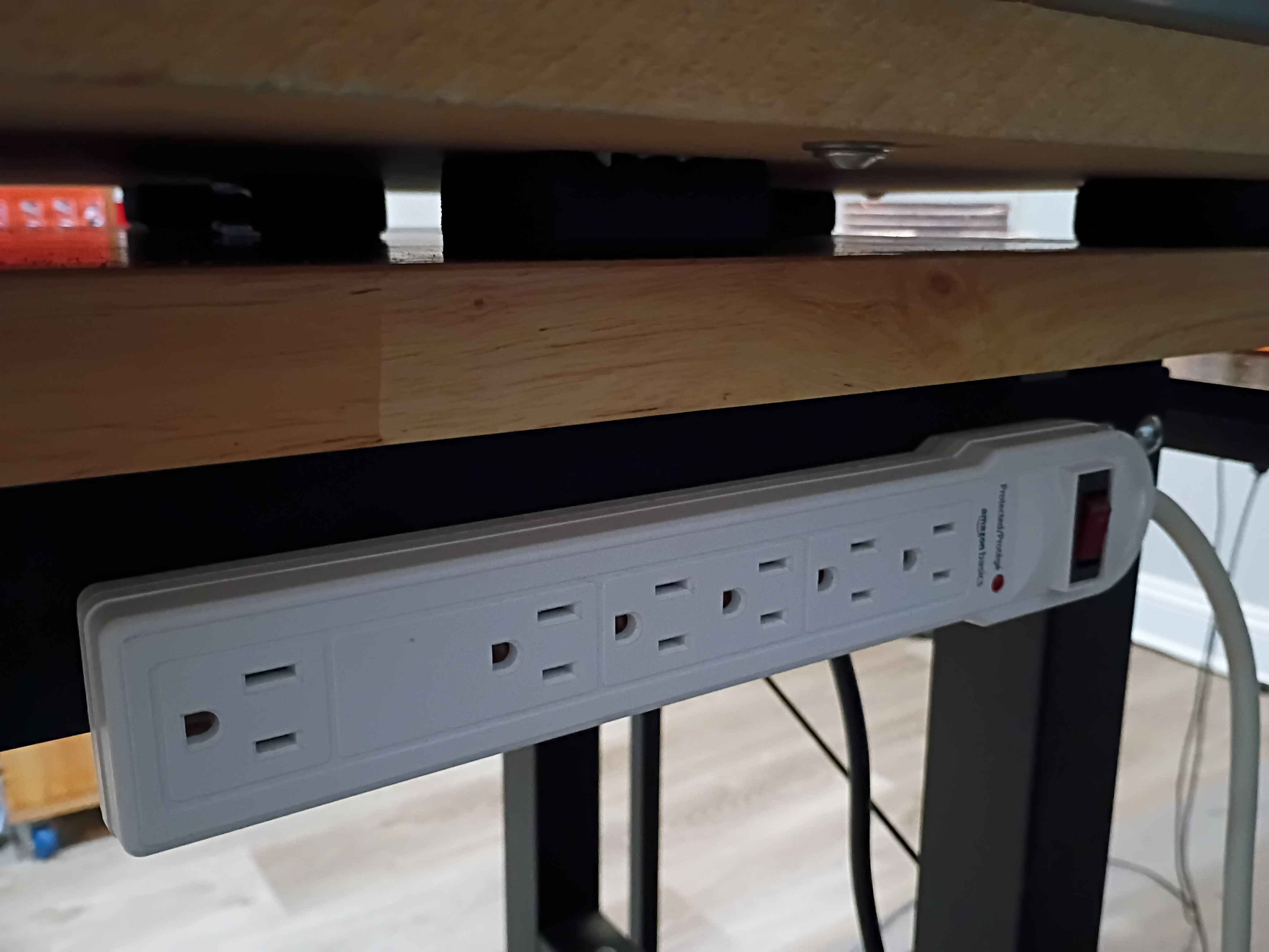
Affixed lights to the top panel, soldered their connection to the control box, and attached the entire top panel to the rest of the frame assembly. Drilled and bolted a power strip to the side of the workbench to power all the CNC subsystems, including the panel lights and ventilation. Did a test and was quite impressed with the lighting. There are no shadows. I wrapped the LED strips in loops at the right angles to avoid soldering, which worked well. 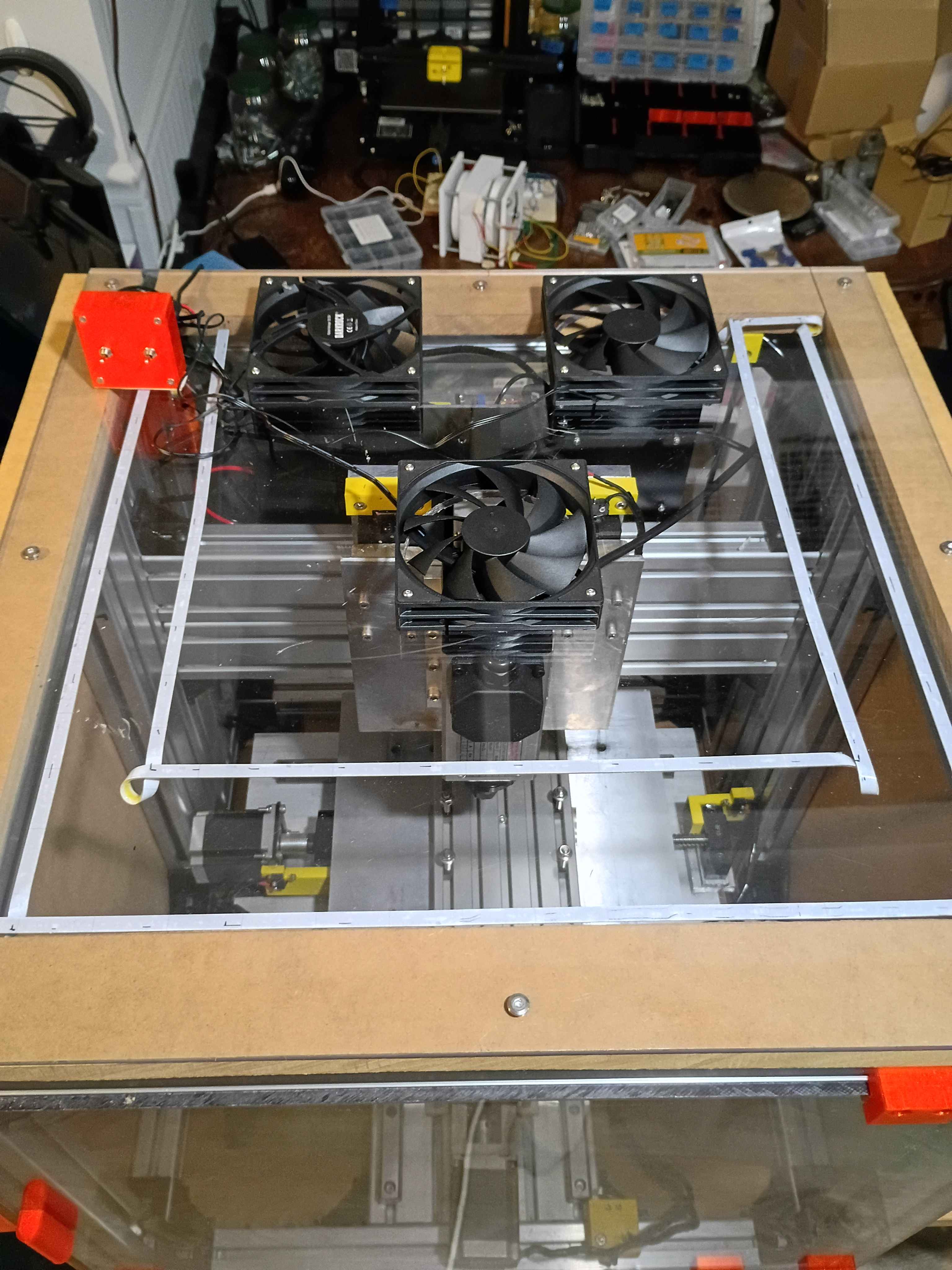
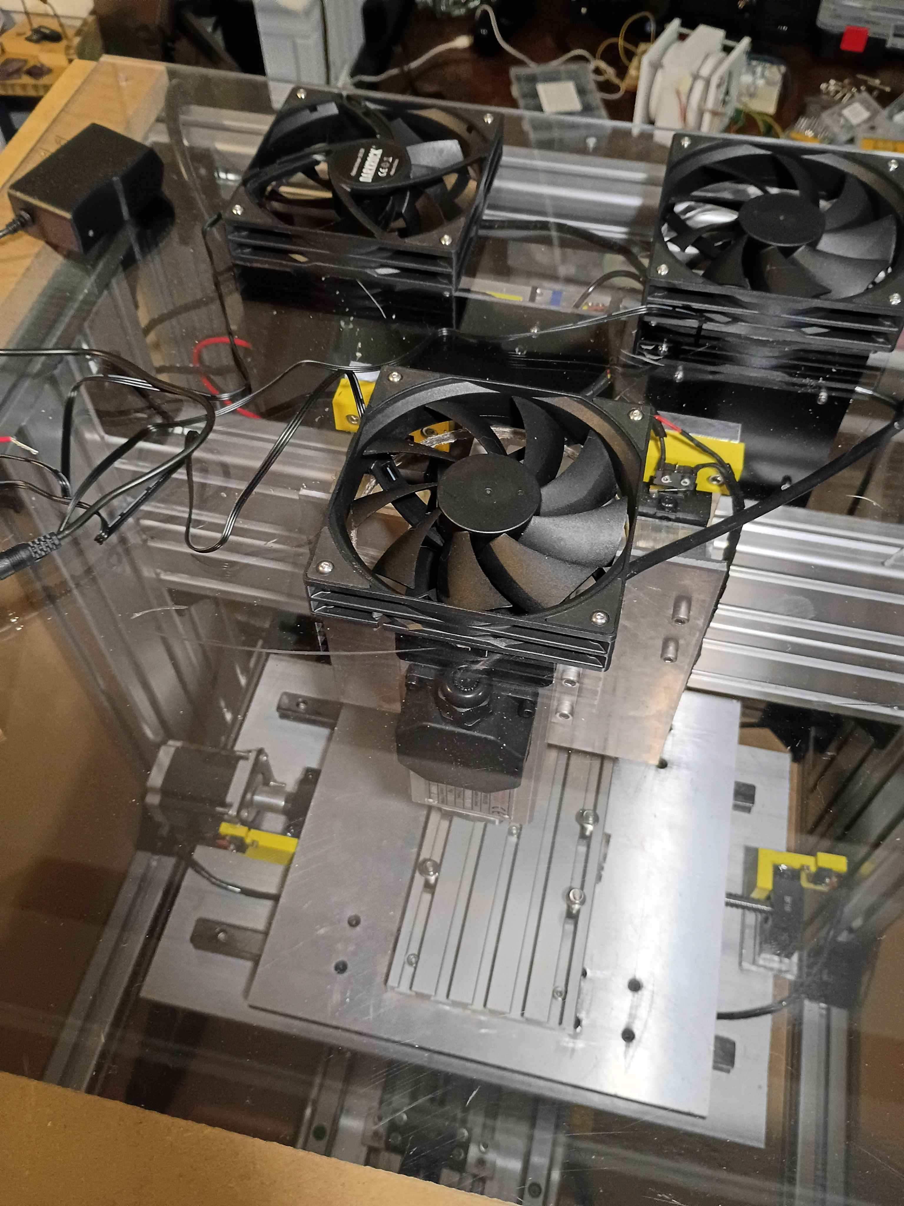
Cut 3x ventilation holes in top panel using hole saw (very hard, I blame the saw). Installed the 3x vent fans with ME screws and tested them. 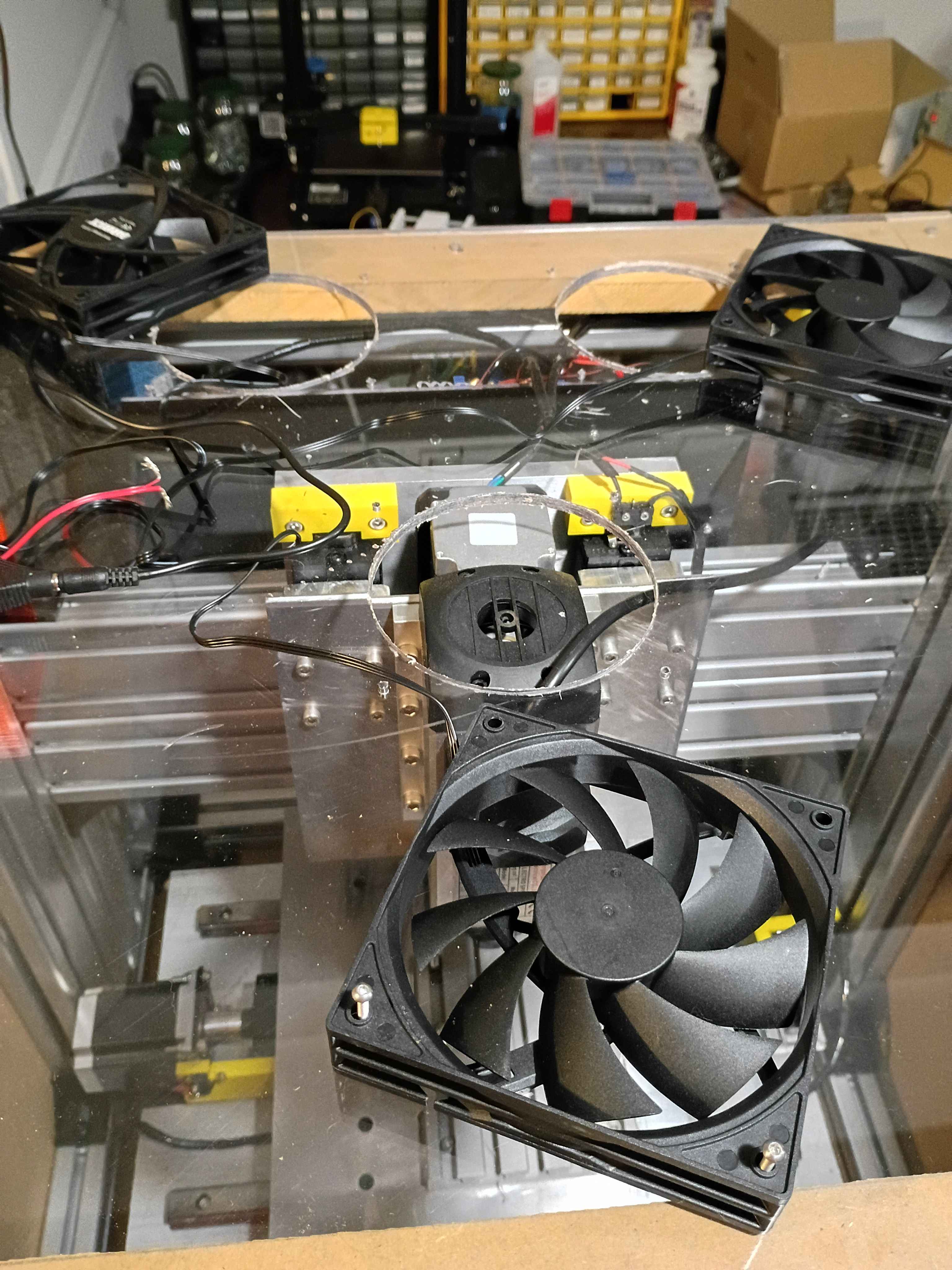
Laid out and drilled holes into upper enclosure panel and MDF spacers. Cut slots for the cables to leave the enclosure. Need a 4.5" hole saw to cut the ventilation holes before I can install everything. 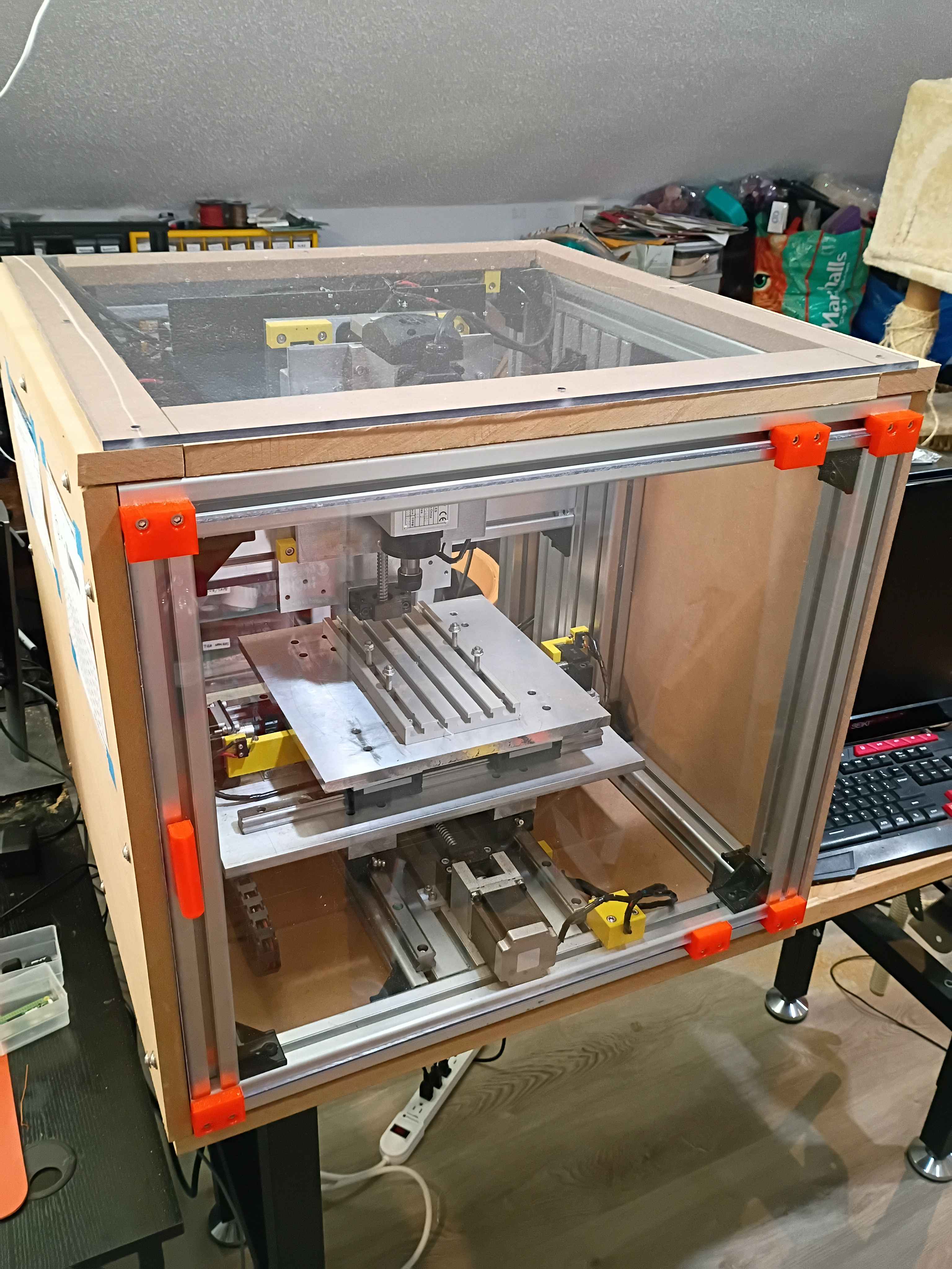
Hooked up camera to Pi zero for garden monitoring. Got the old discord bot control working, though I think I'm going to pivot to a Tailscale VPN to get a less bloated and less precarious setup. I did a preliminary setup connecting a few devices and hosting a simple webpage with a Flask server to get user input and show a photo snapped by the camera. 
Took inventory of last years automated garden pump system. Saved cronjobs and scripts from old system and reflashed a new Pi Zero with Raspbian. Brainstormed some additional functionality and purchased some peripherals online.
Began working on the circuitry and control box for the lighting and ventilation. Soldered up the circuit. Designed 00001-020 and -021 control box parts and began printing. One will print overnight. 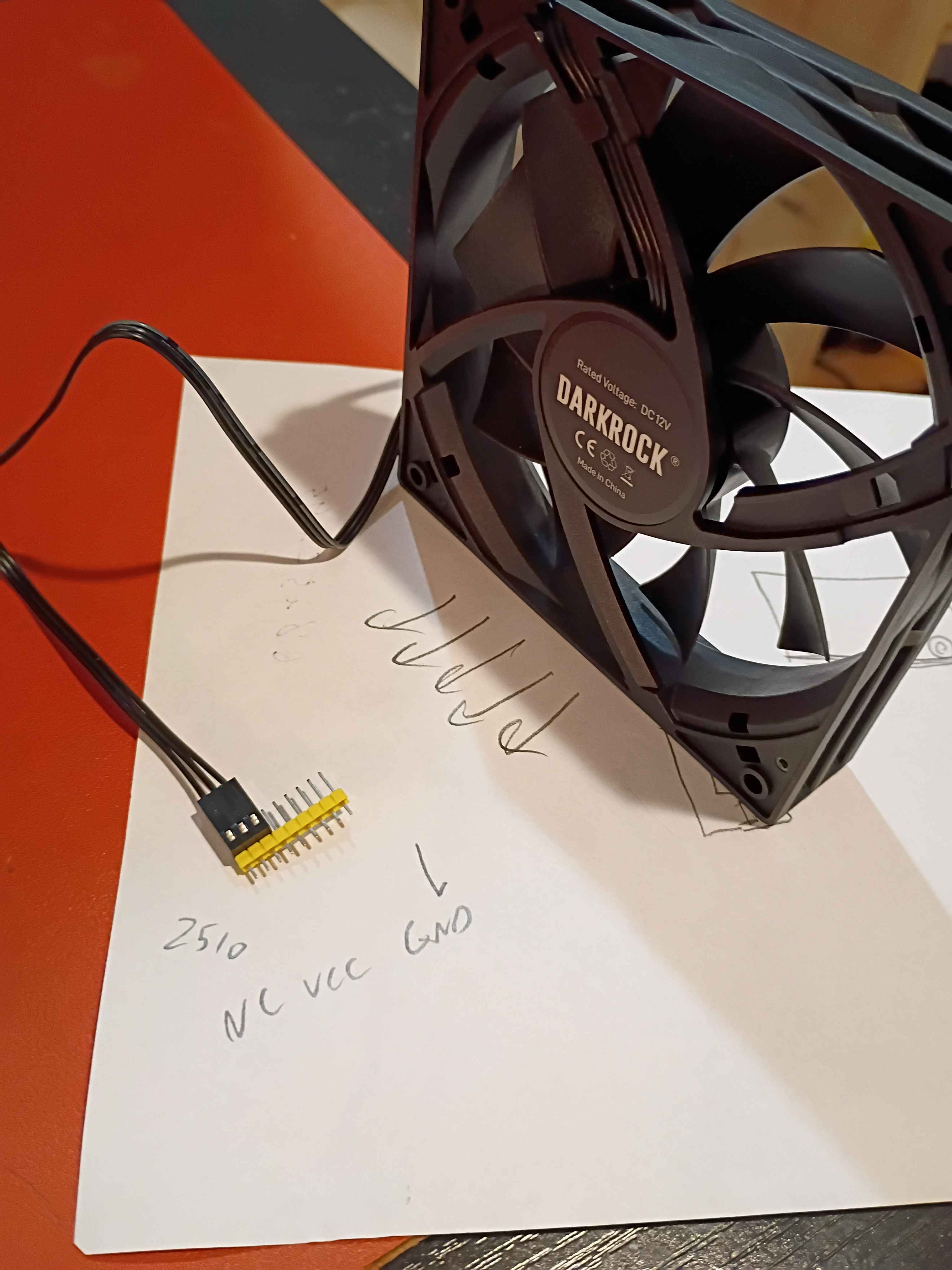
Added chamfers to the handle side of the front sliding door and also sanded the other sharp edges smooth for safety. That really helped the door slide in a lot more easily. Also cut 4 strips of 3/4" MDF to raise up the eventual top polycarbonate panel enough to clear the top of the spindle air intake in the highest z-axis position. 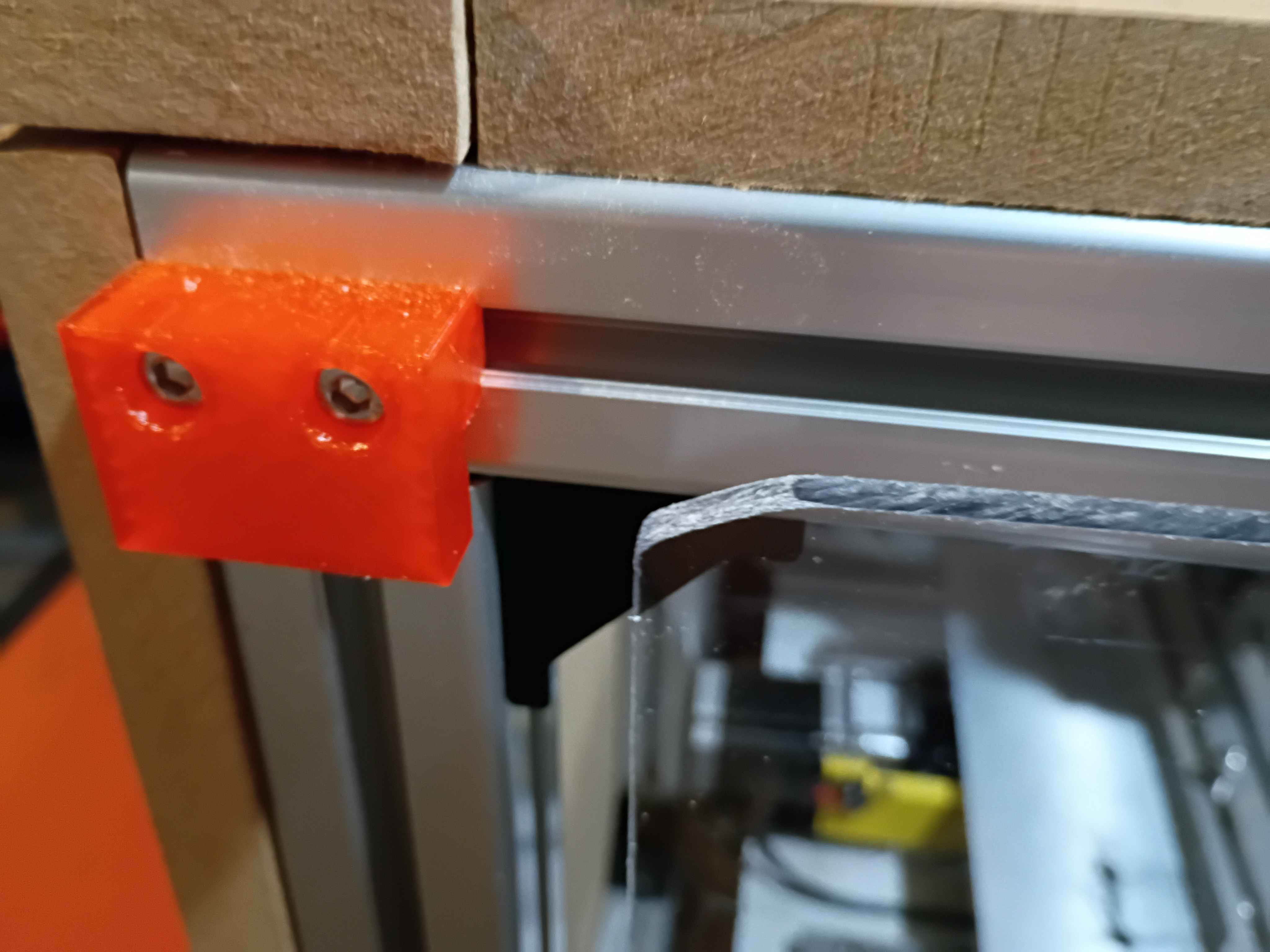
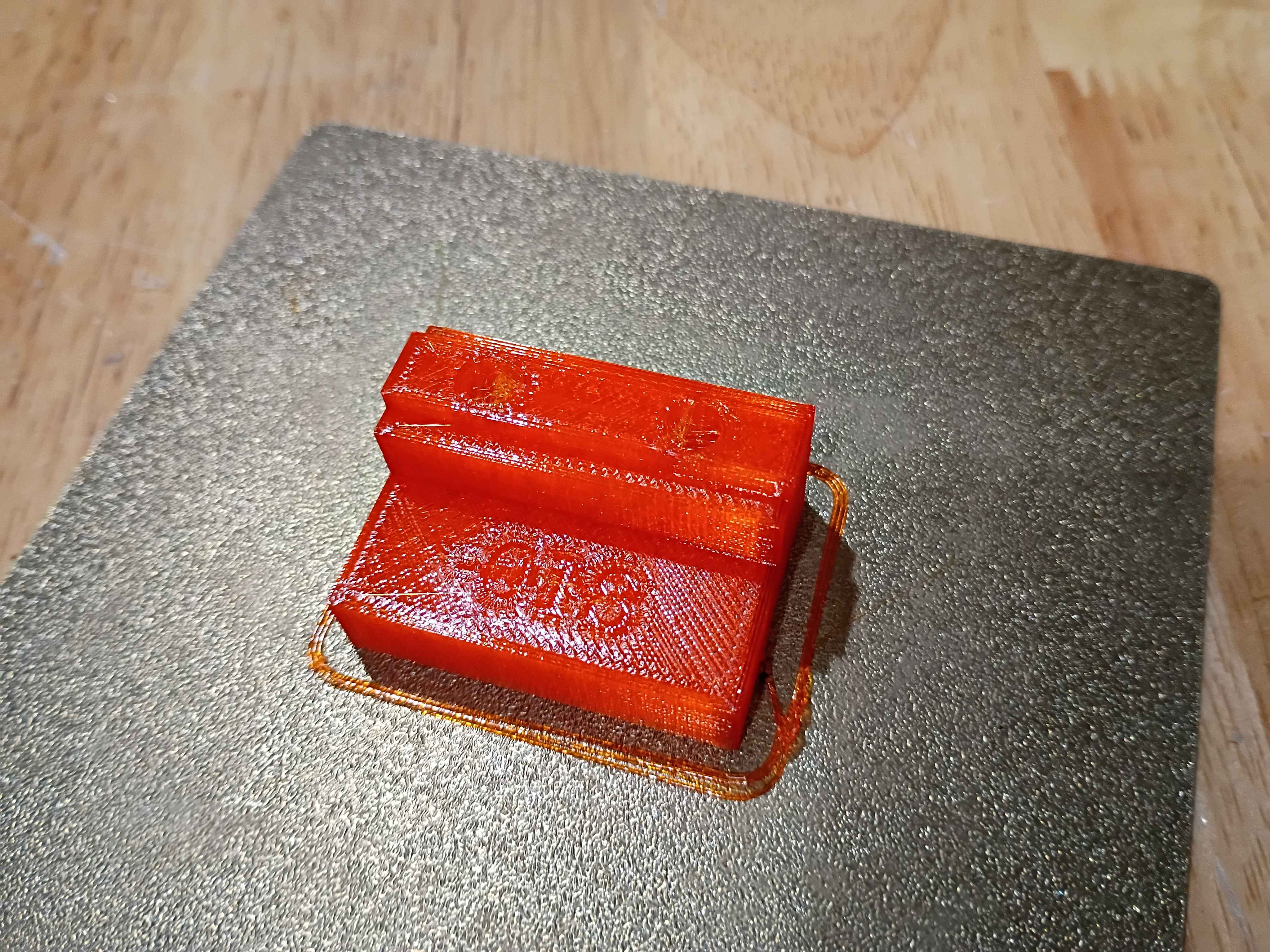
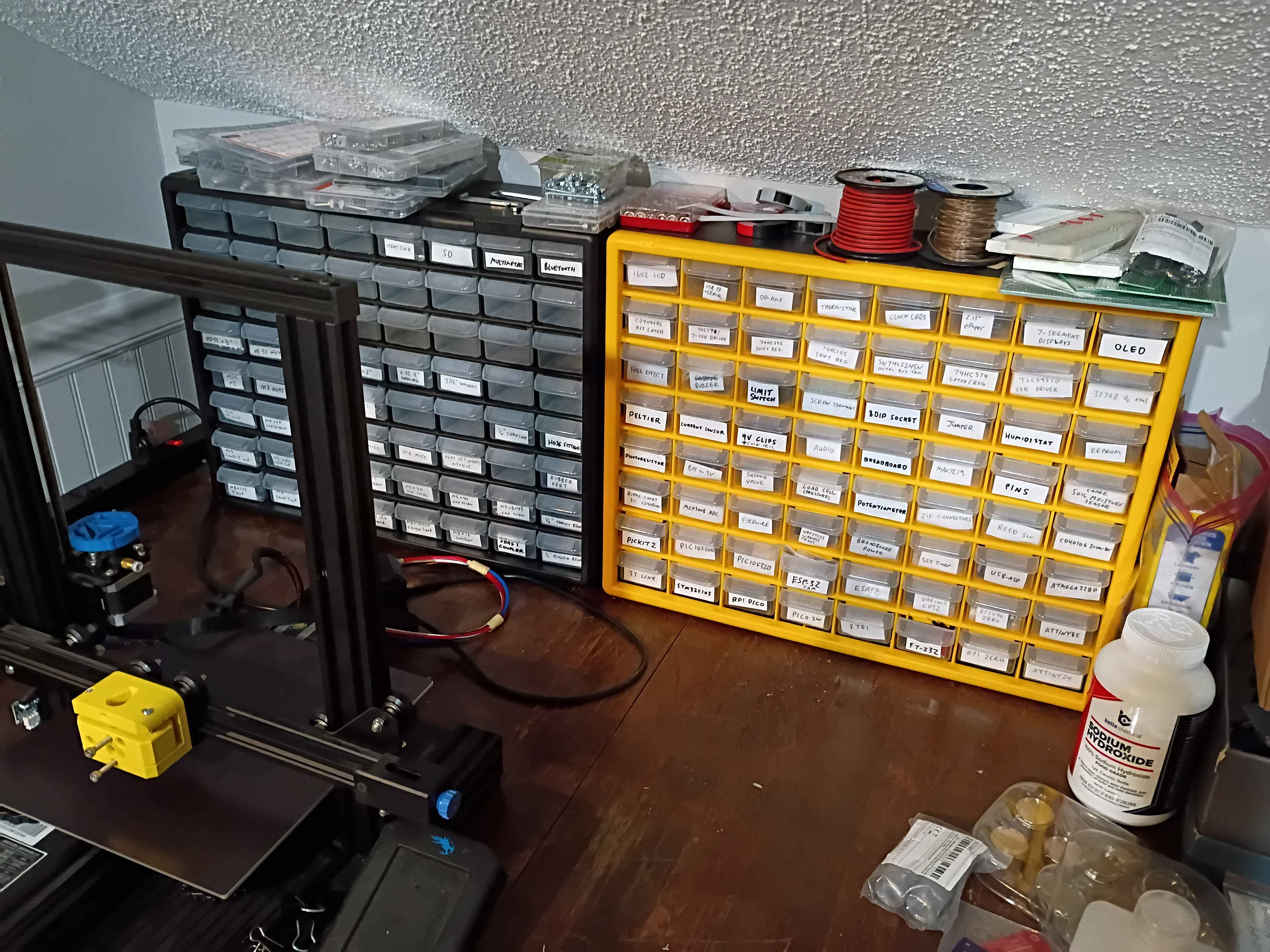
Sorted most heavily used hardware (M5) into briefcase bin with labels. Designed and printed small cubby to keep similar parts with different coatings segregated. Will do the same for other hardware eventually. 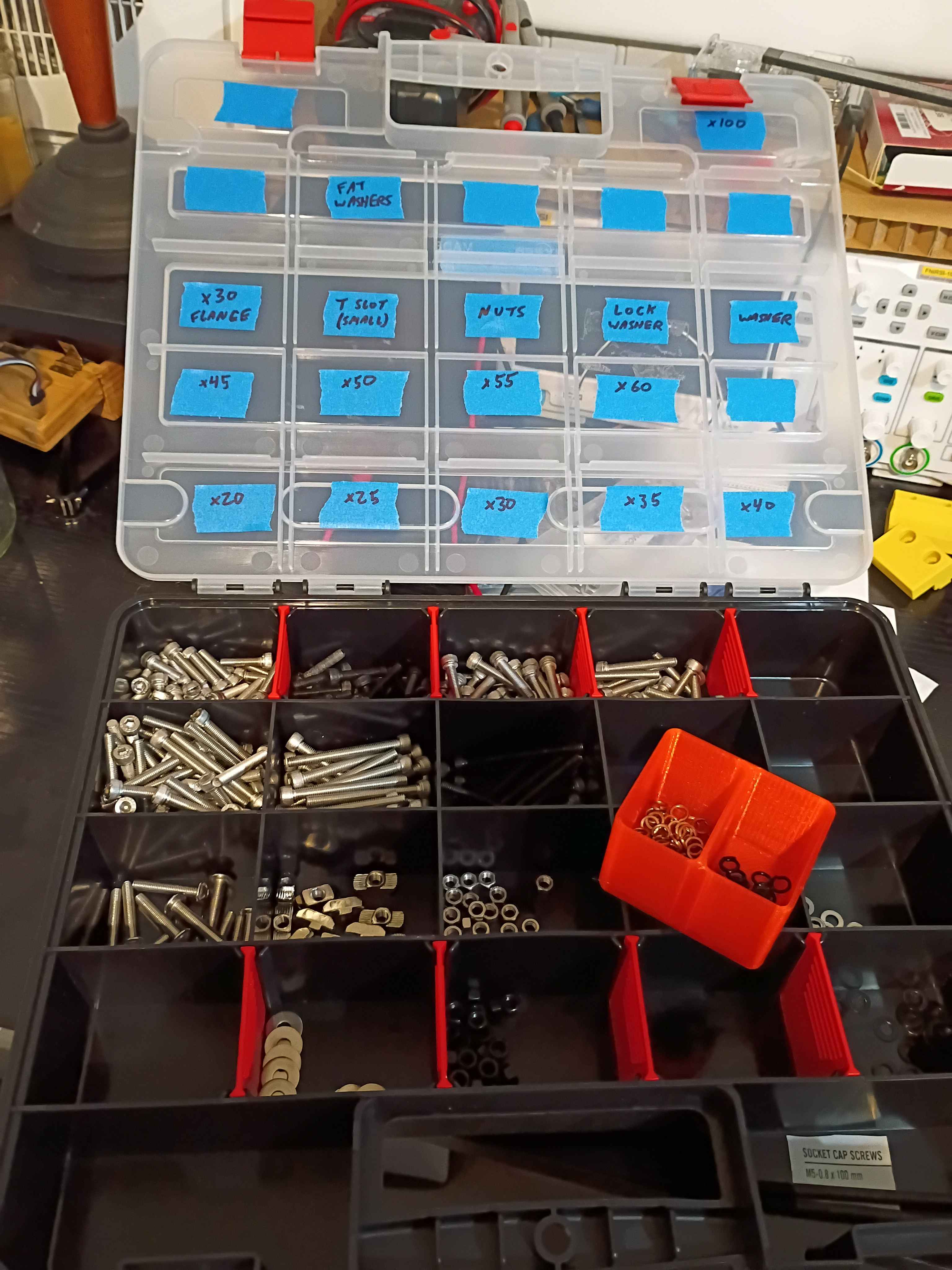
Tested stiffness calculations for rectangular bar and I-beams, and corrected some errors insodoing.
Designed and printed 00001-019 handle for front panel. Did not need any support material for the small overhangs. Melted M3x4x5 heat set inserts into the back. Cut the front polycarbonate panel to size, and drilled and countersunk holes for the M3x12 flat head screws to sit flush. Installed the sliding front panel door using 6x 00001-018 brackets, with the middle two biased toward the side opposite the handle, to keep supporting the panel while it is open. It is a bit dangerous on the free end when the door is open, and it's kind of a pain on the handle end to line it up when closing the door, so I might add a chamfer to all 4 corners. Also cleaned up some of the electronics yesterday, but forgot to record that. 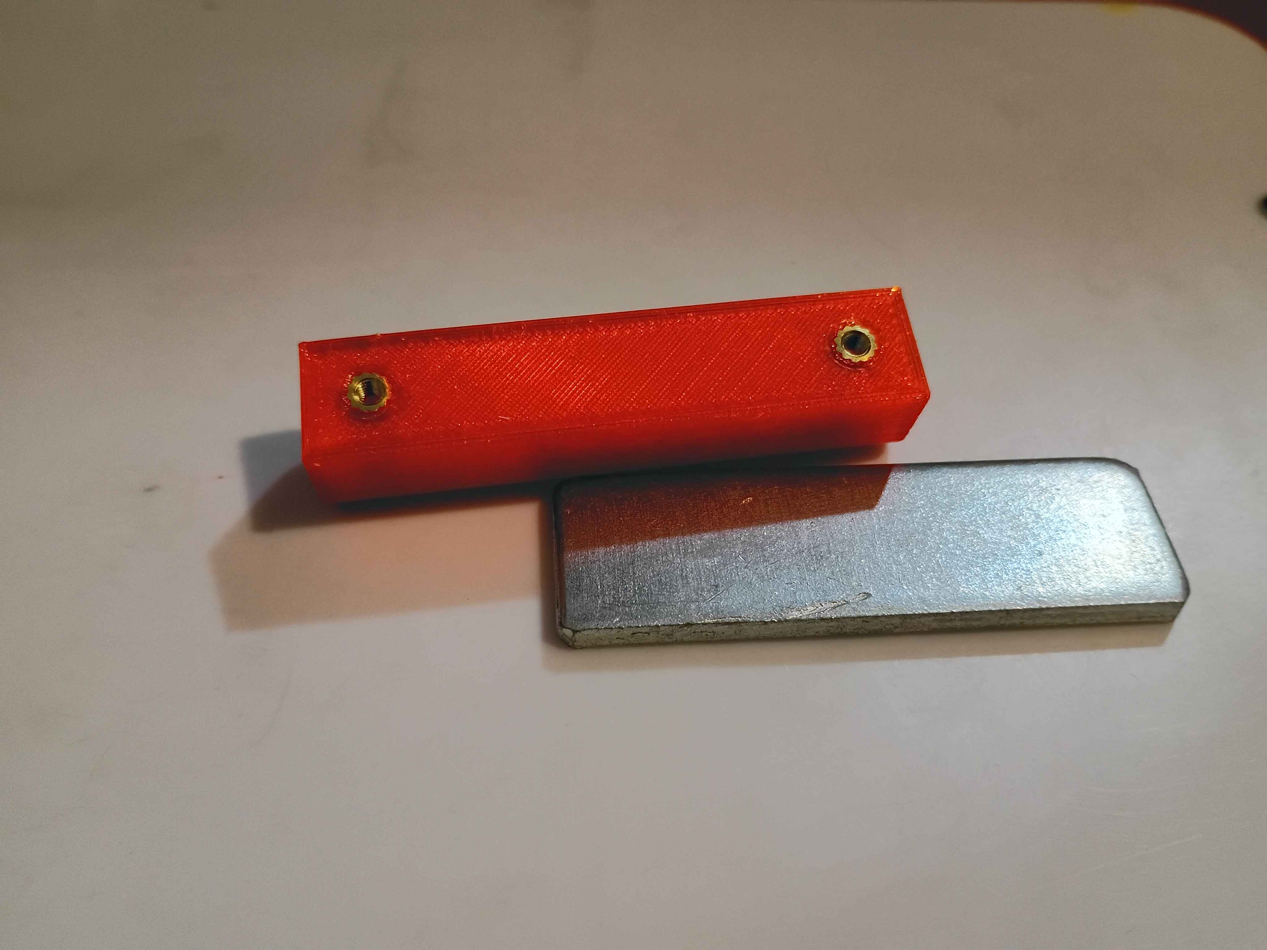
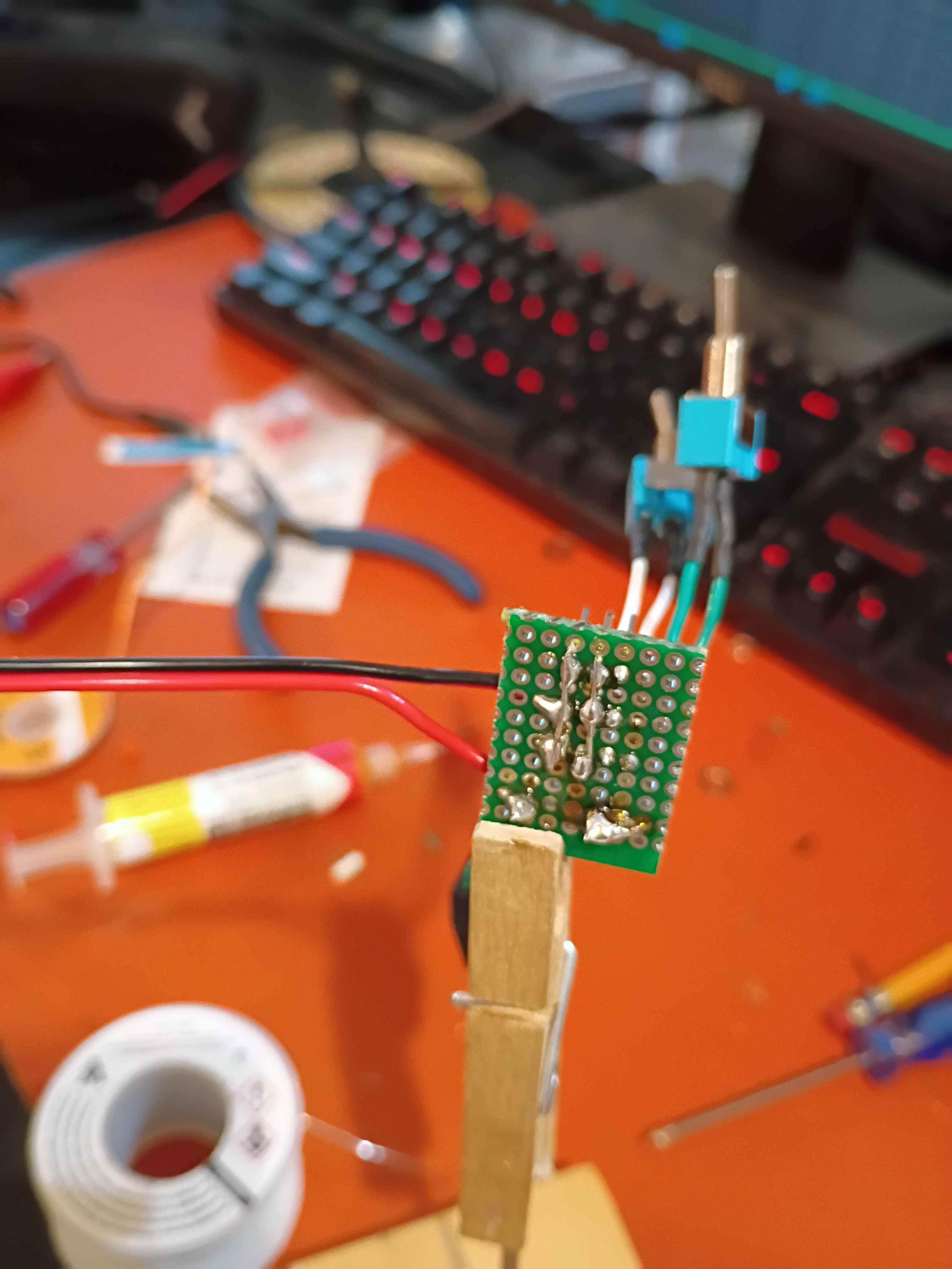
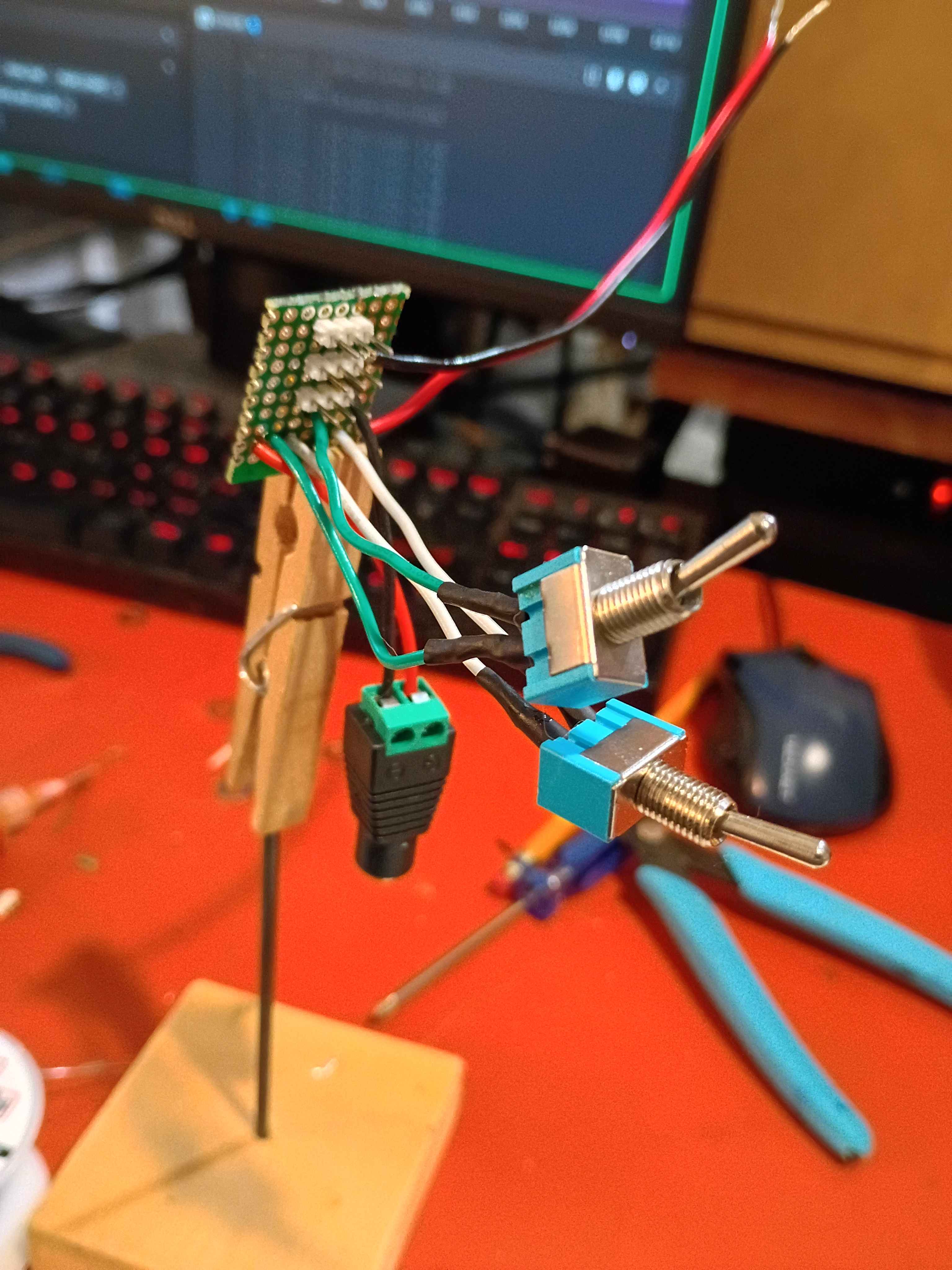
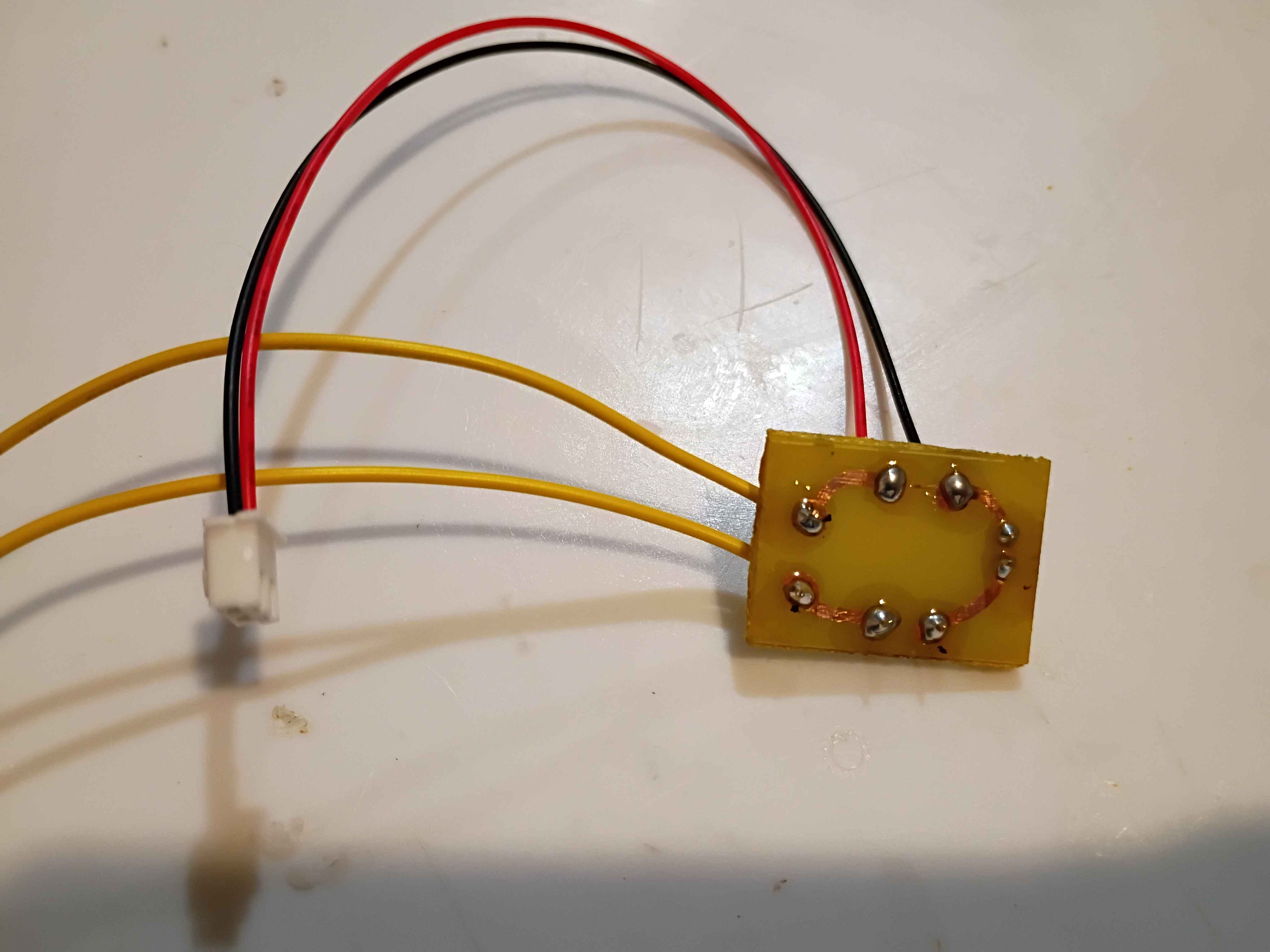
Diagnosed and repaired non-functional (newly purchased) RGB LED wall clock for a client. The issue was either a bad shunting diode on the power input or a faulty connection with the DC power barrel jack. Recorded a video of the repair, quickly spliced it together using Kdenlive, and posted it to the company YouTube channel.See video of repair. 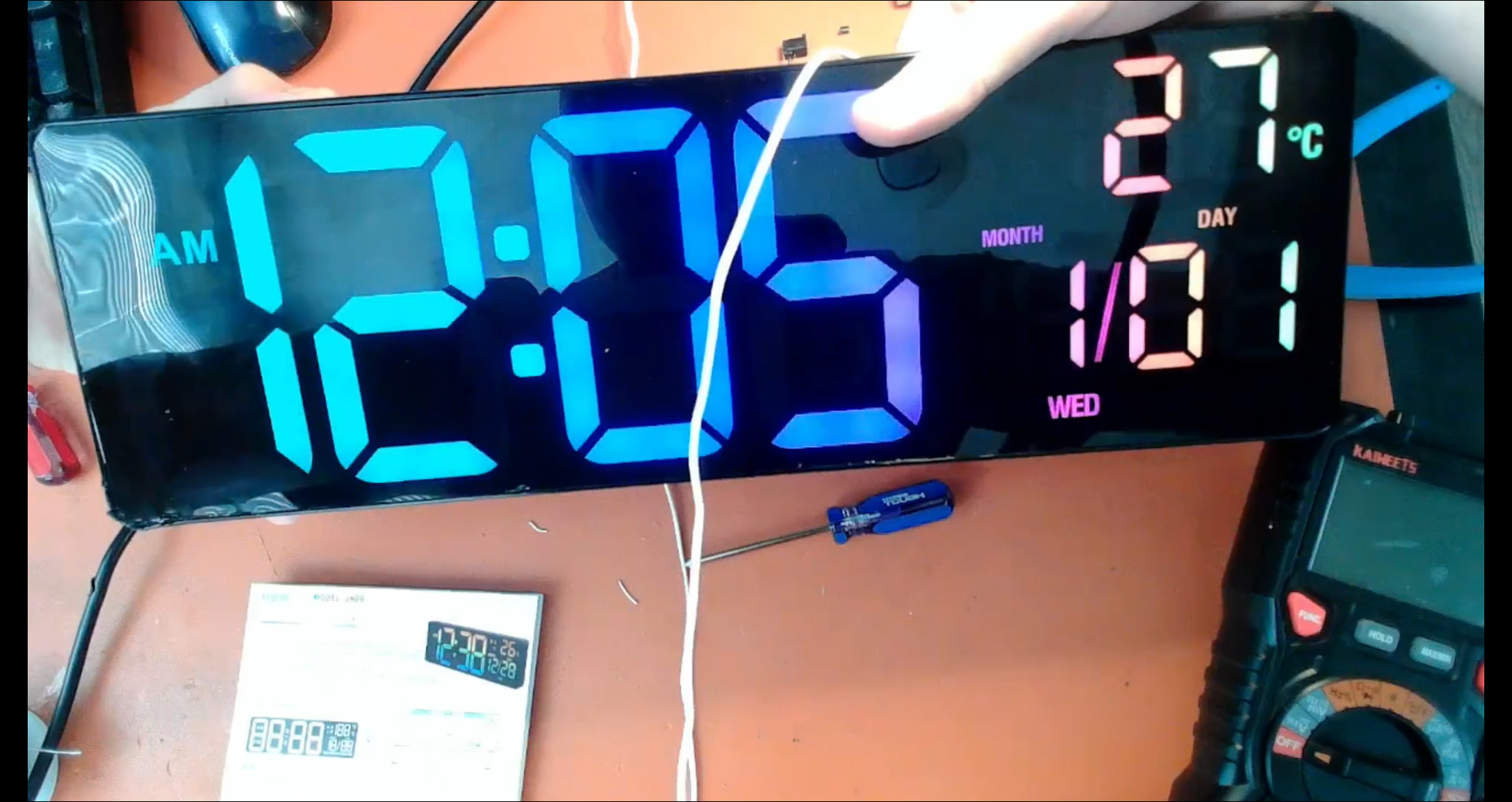
Updated parts of website that Mary-Bot does not have access to regarding recent organizational changes. Formally ended the Pentecost-Pursuits initiative.
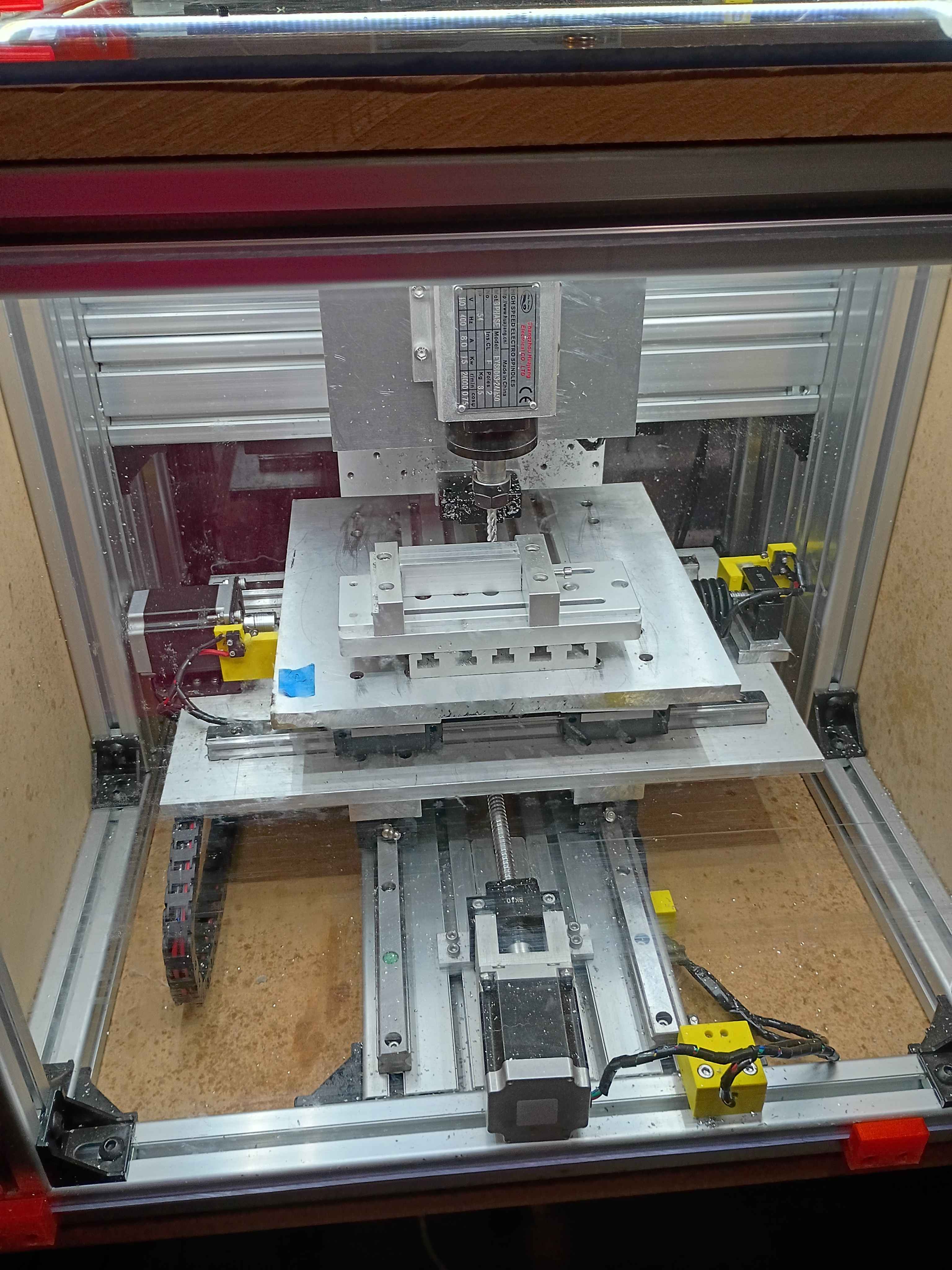
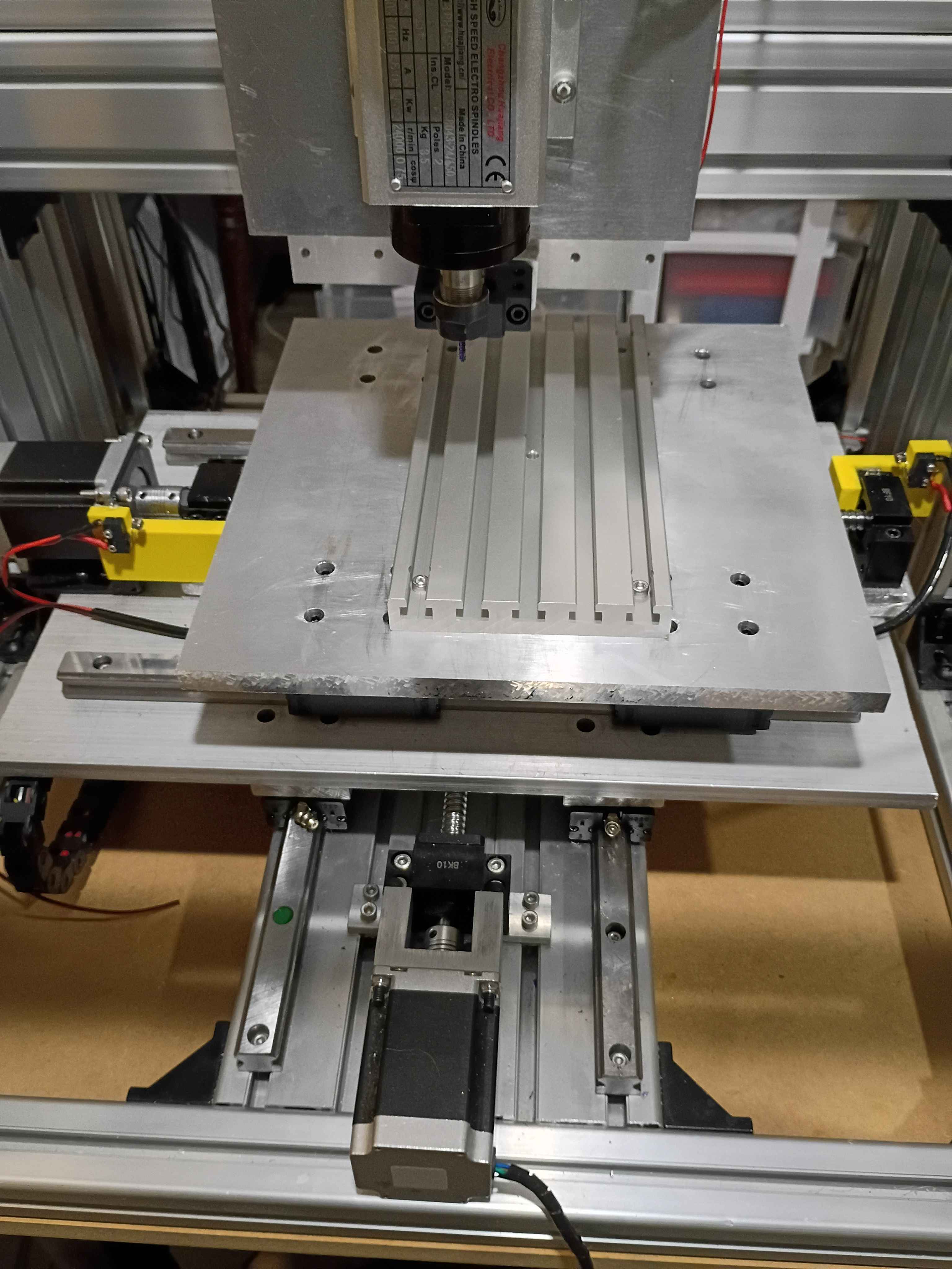
First chips on CNC. Cut 10mm cube into MDF at 300 Hz or 18000 RPM using 3.00mm endmill. Something about the depth seems off, but the x/y are spot on. Need to think a bit about how the x/y directions are oriented. See video. 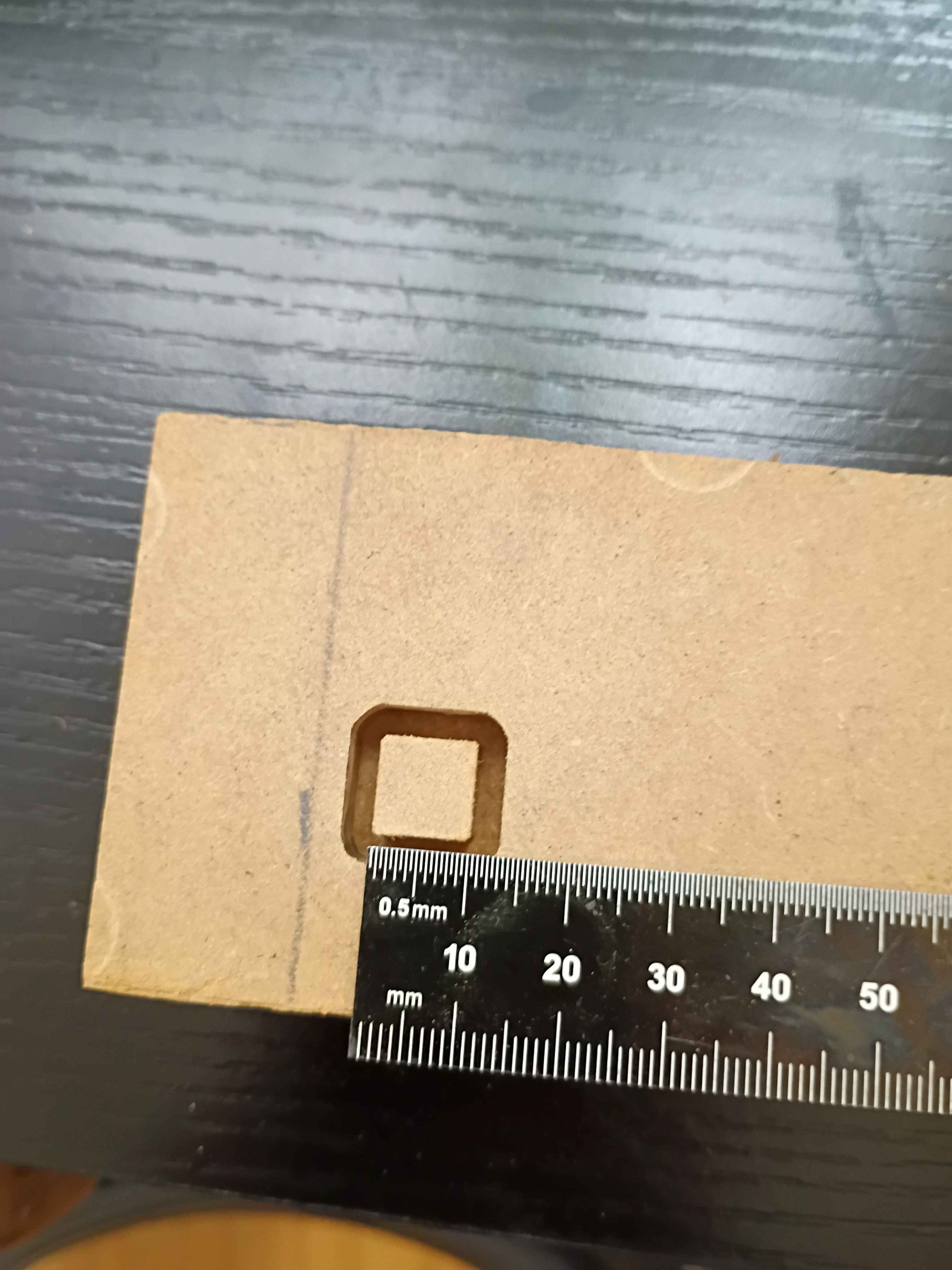
Cut polycarbonate back panel and installed it with all the necessary brackets, including some old repurposed ones. Routed the wires in the back area using some 00001-017 brackets. Cut the side MDF panels to size with a flush cut saw. Designed and printed a first 00001-018 bracket for the front sliding door, which is an exact copy of the 00001-016 with an additional .5mm of room for the polycarbonate panel to slide, and printed in translucent orange PCTG instead of ASA. It also has the part number embossed in one of the non-visible surfaces for easy identification. 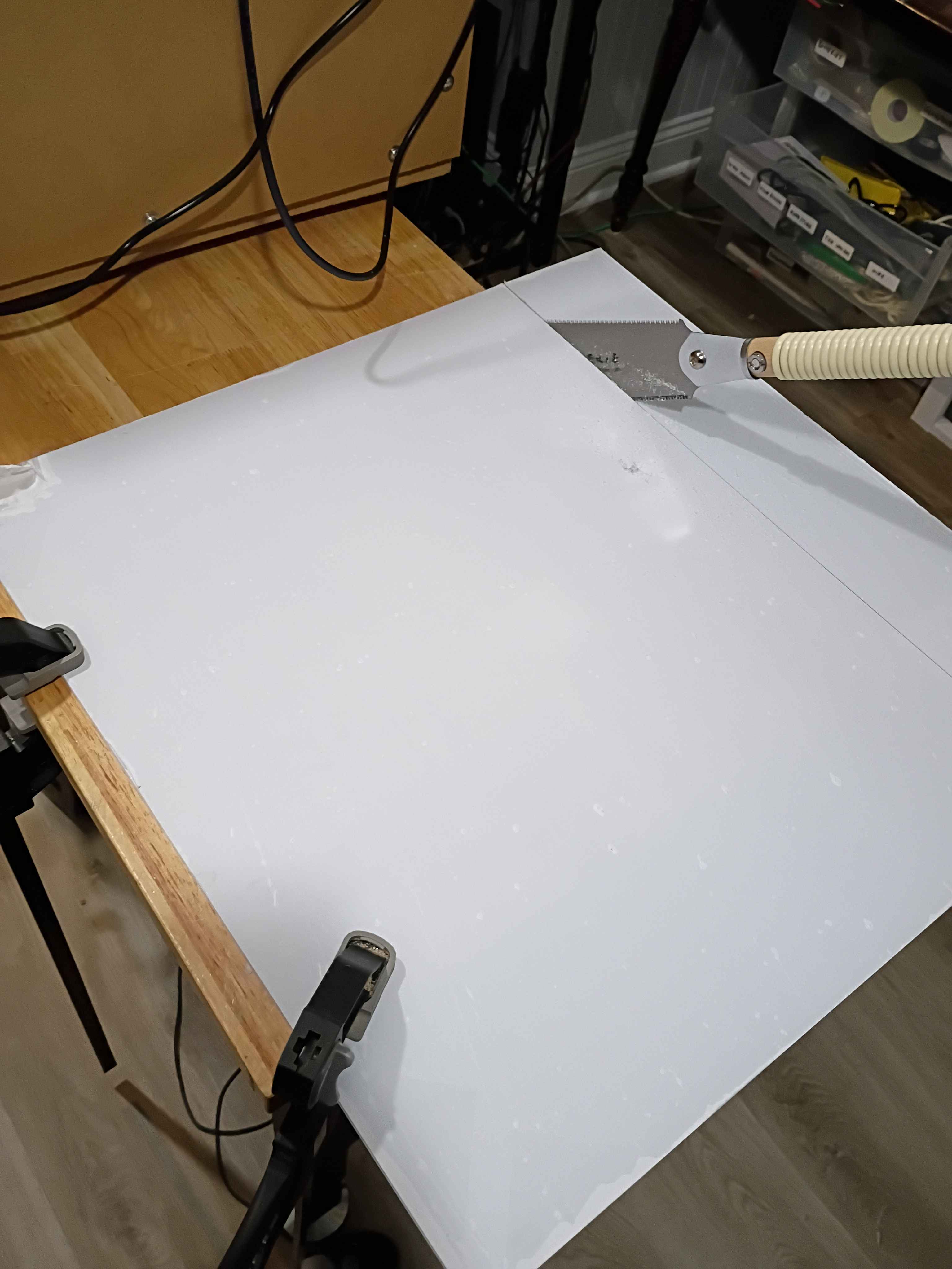
Soldered, rerouted, and rewrapped some of the wires for the electrical panel. Also printed out some prototype brackets for wire routing. 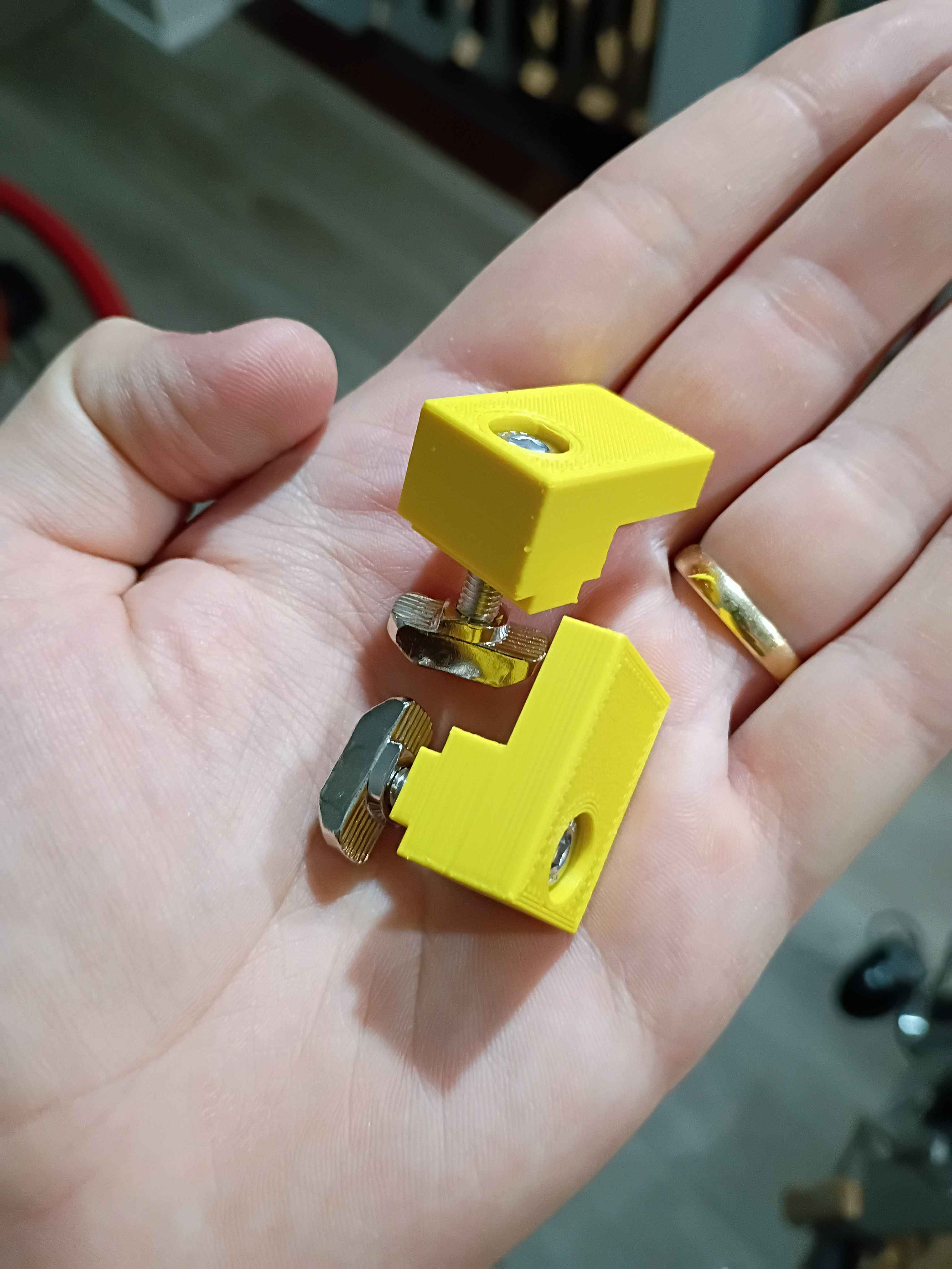
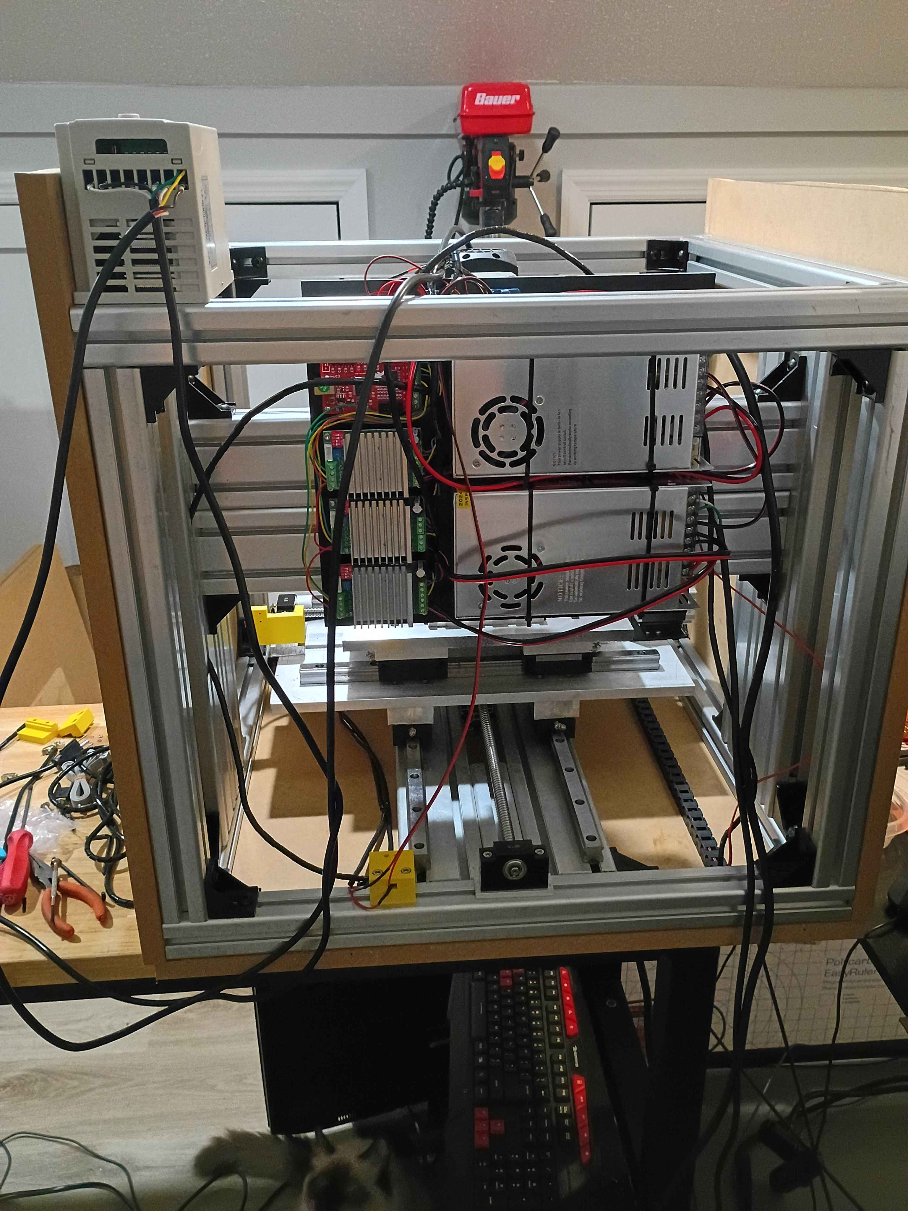
Though it took an insane effort, got the entire electrical system mounted up and rewired, after trimming the lead wires shorter. Accidentally had it upside down, too. Also printed all the door slide brackets. 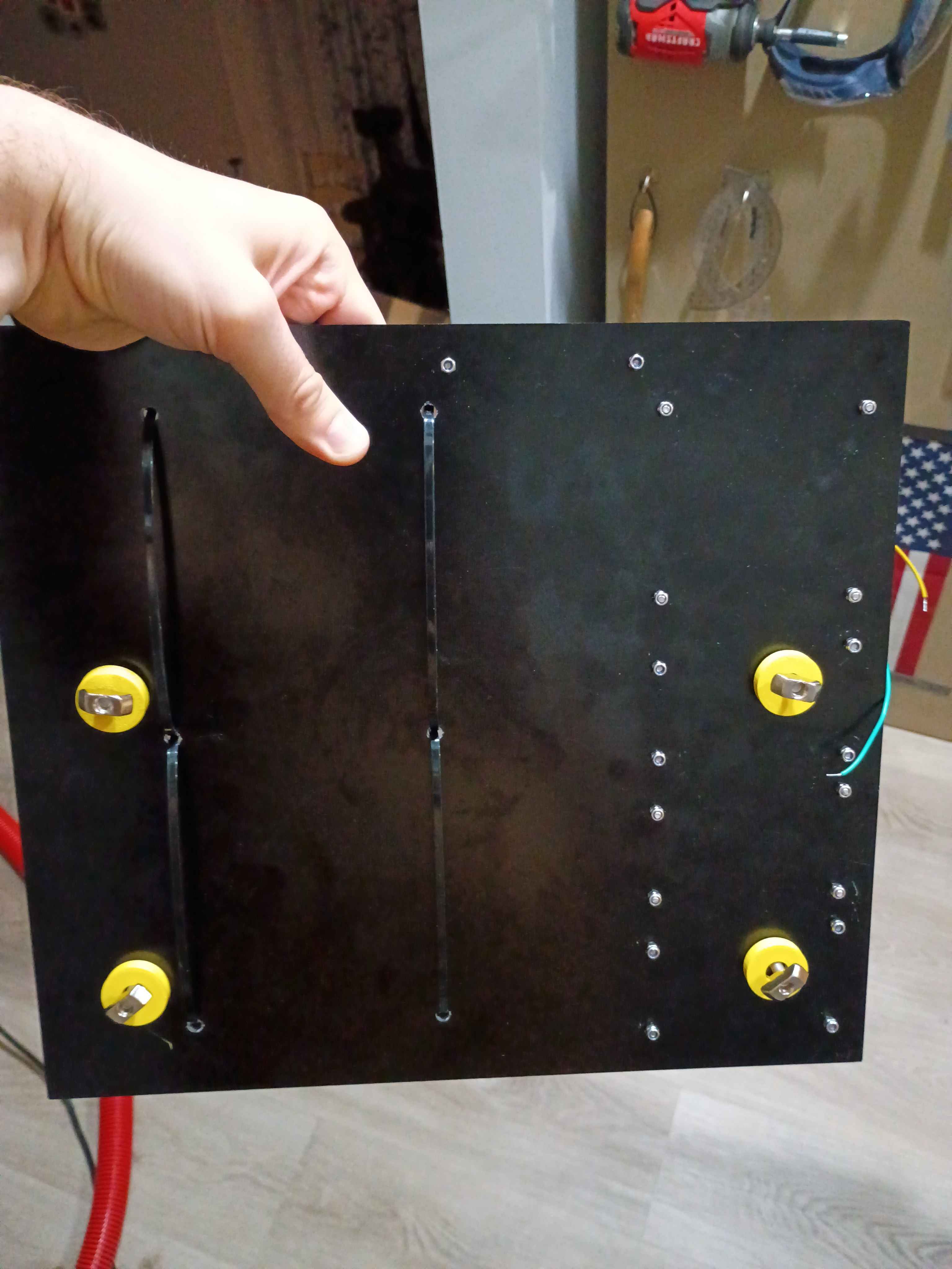
Designed and printed 00001-016 sliding door panel brackets that accept 2x M5x20 bolts to attach to 4040 T-slot nuts. It worked successfully on the first attempt. Printing 7 more over the next couple days. 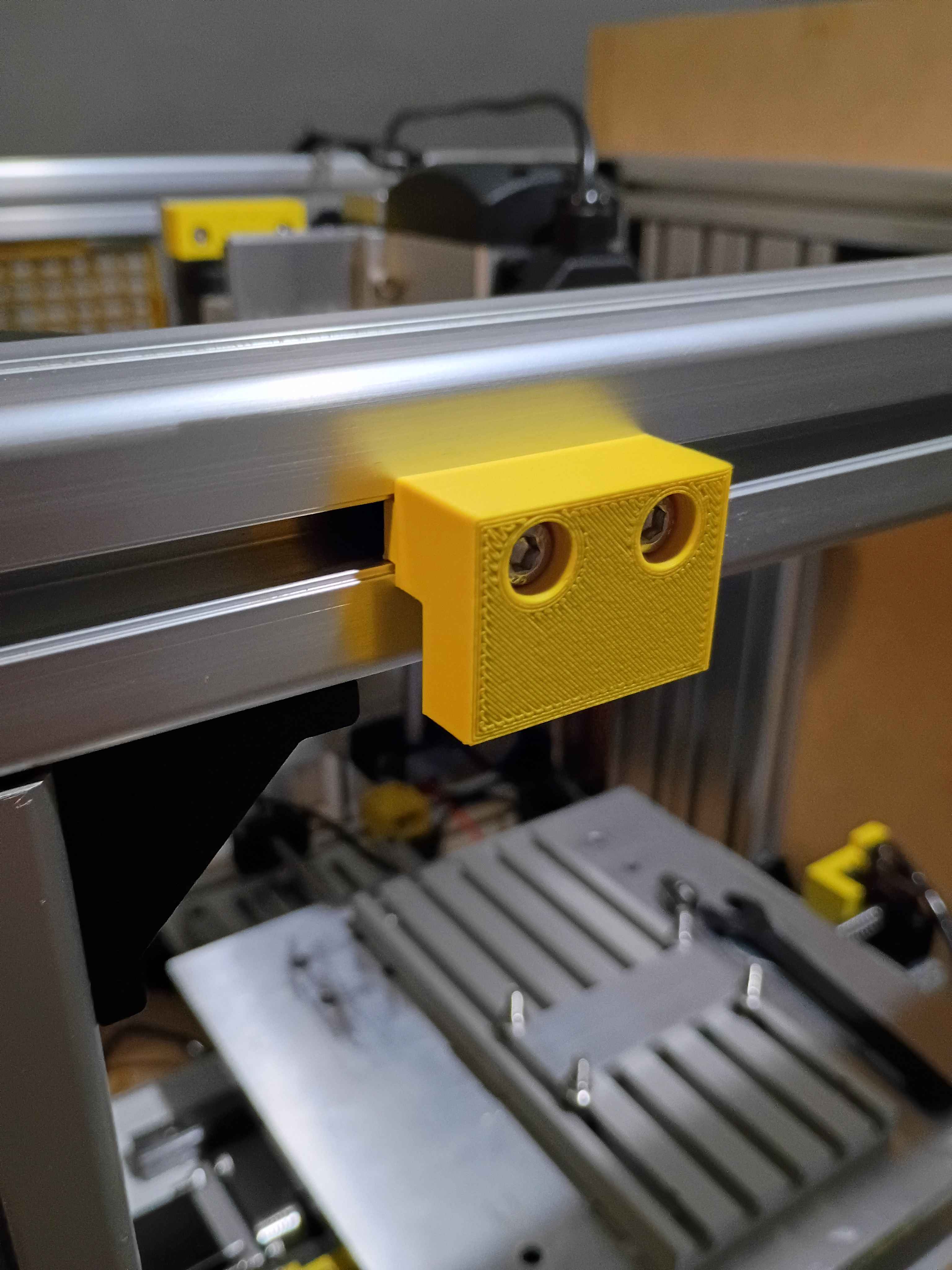
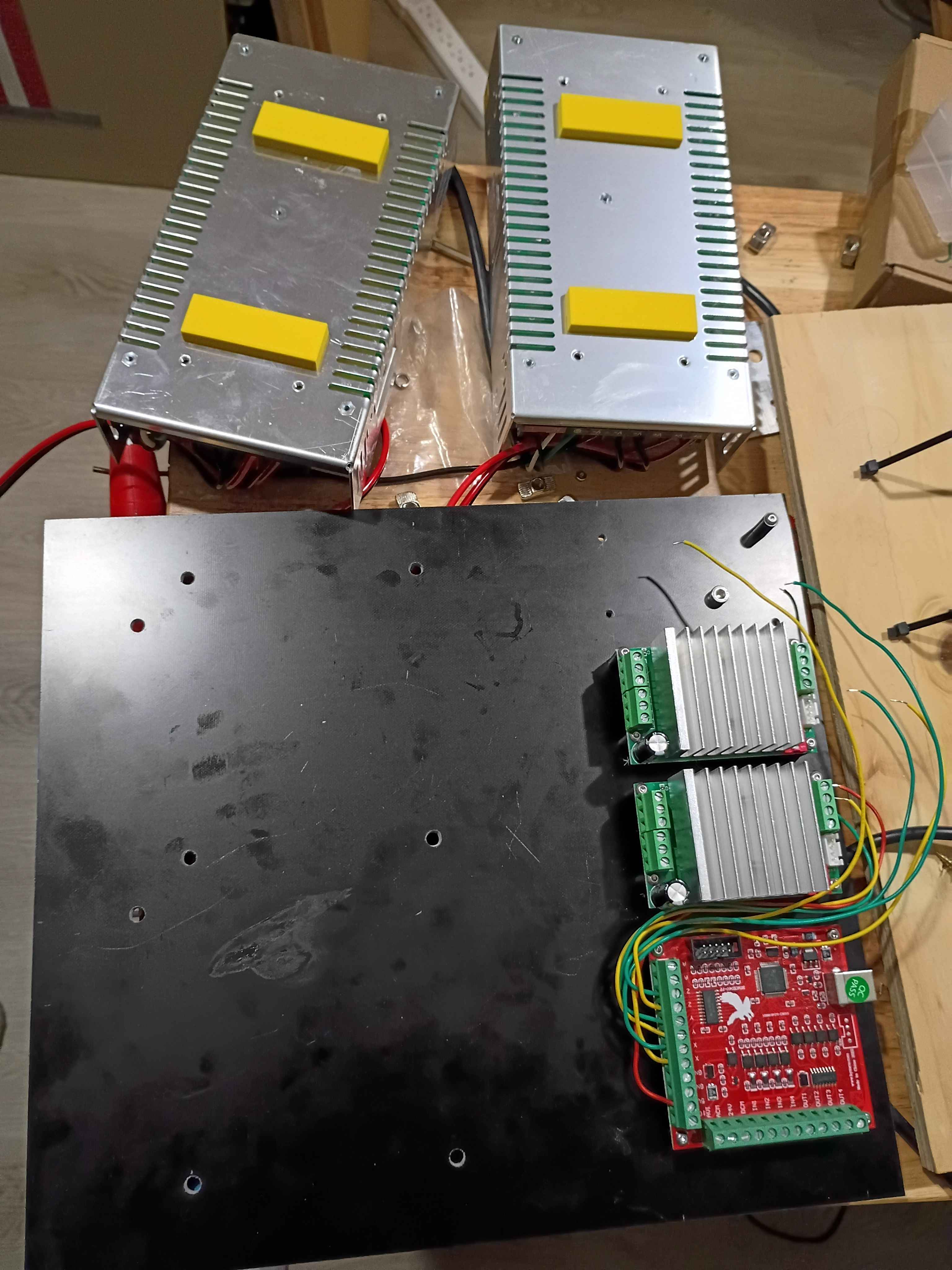
Drilled holes in G10 fiberglass electrical mount plate, began to mount up some components using spacers, realizing I will need some more M3x20 screws and a set of stubby Allen wrenches, and designed & printed some rectangular 00001-014 spacers for the inverters and some cylindrical 00001-15 spacers to mount the entire panel to the aluminum frame. While this will work, it would be better if I planned out the electrical subsystem placement to not shroud the hardware mounting the panel to the frame underneath the hardware mounting the electrical components to the panel, as that just makes things unnecessarily difficult to install. 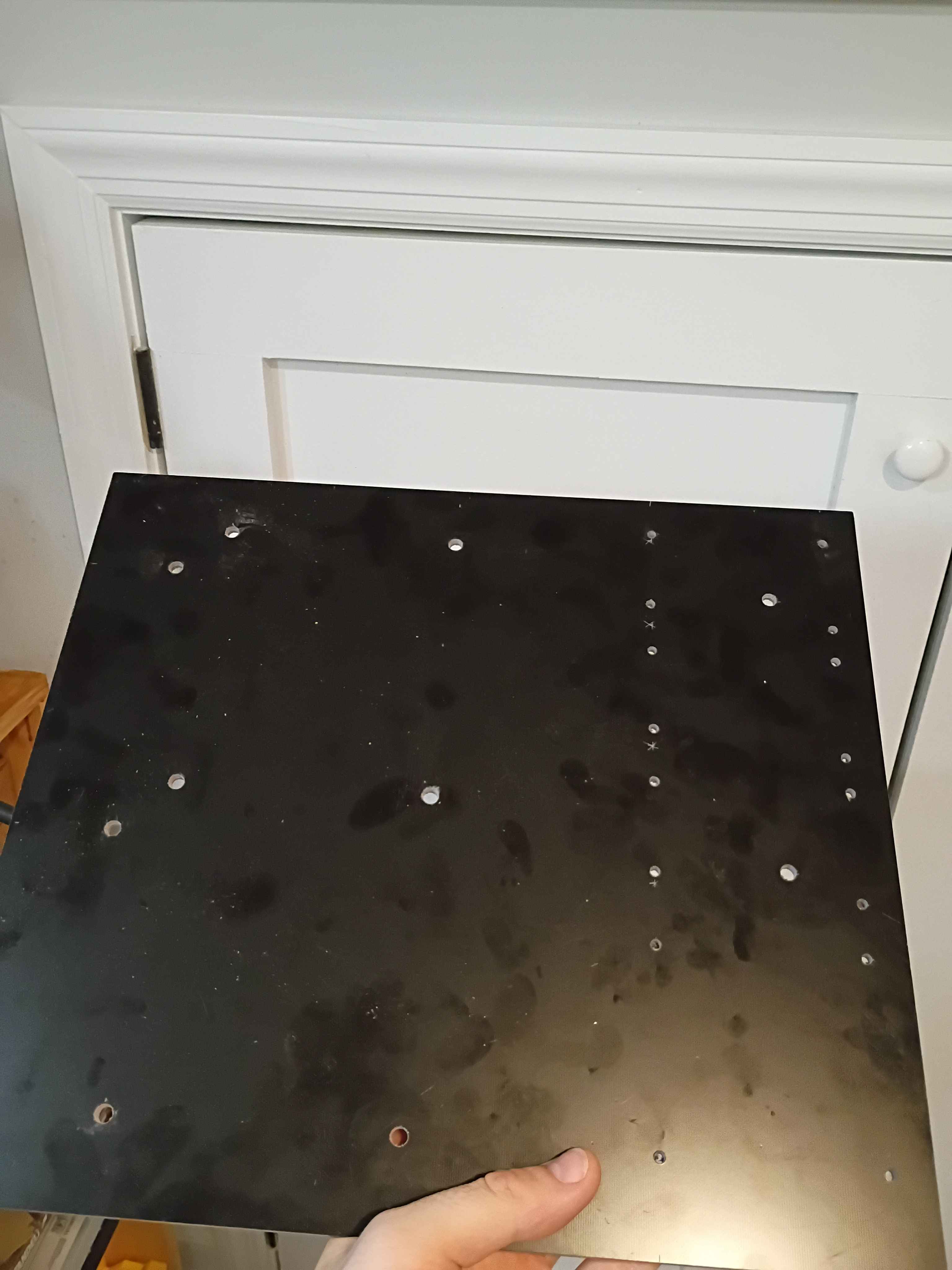
Fixed an error in the inertia evaluation code and reported some more properties related to the individual component densities.
Added sectional property evaluation code, untested. Should test with a few simple cases tomorrow. I-beams and simple composite sandwich sections.
Planned out electrical panel drill pattern based on the initial plywood version, but slightly less flammable since it will be made of G10 fiberglass. Received the laminate today, but waiting on spacers. 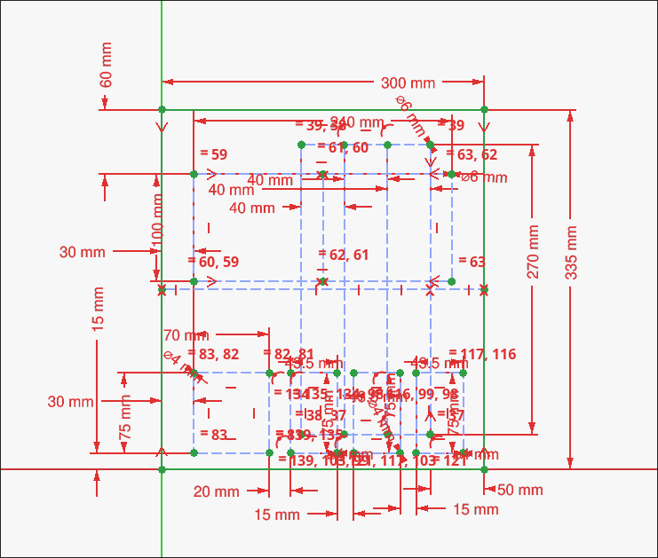
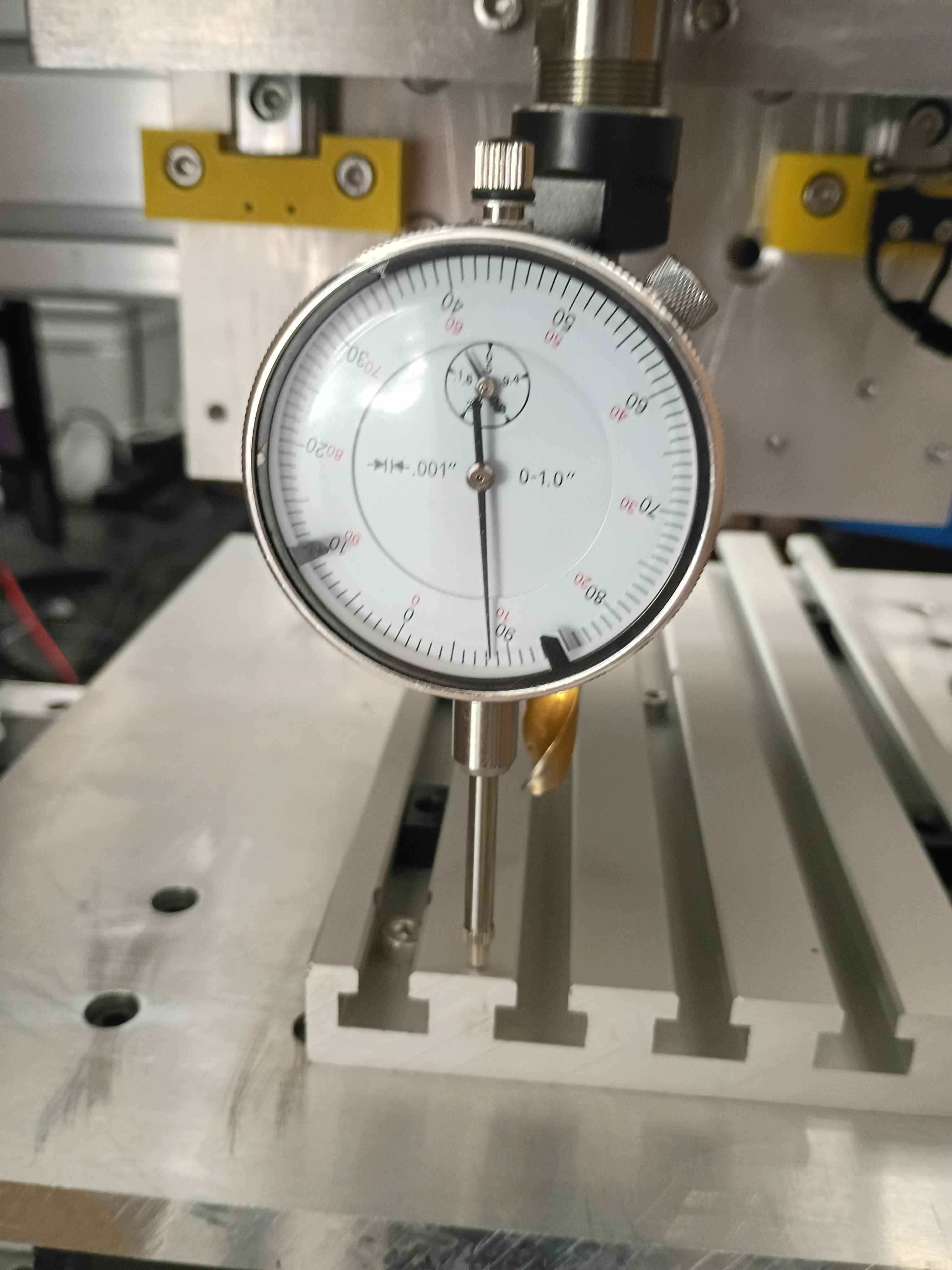
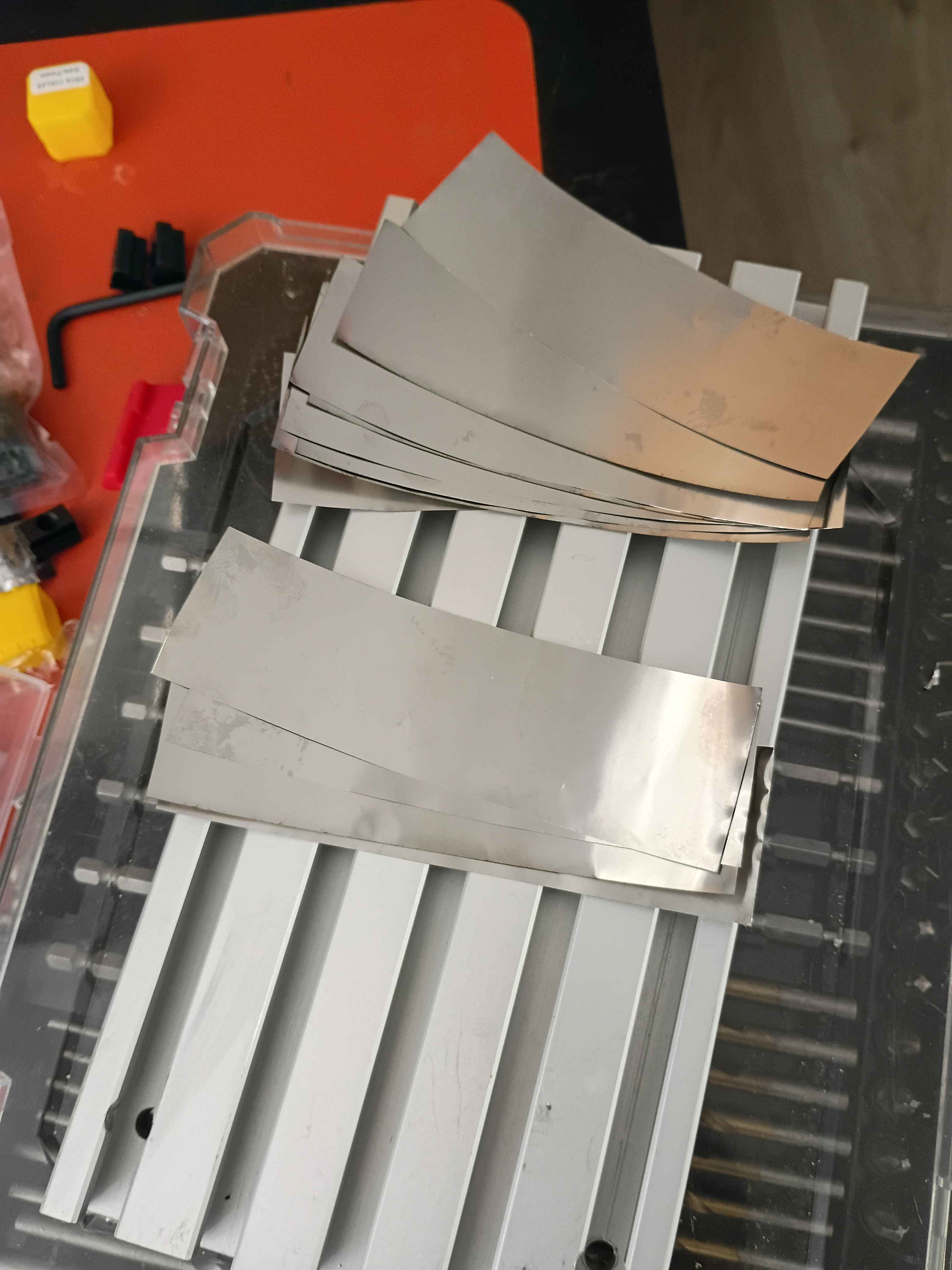
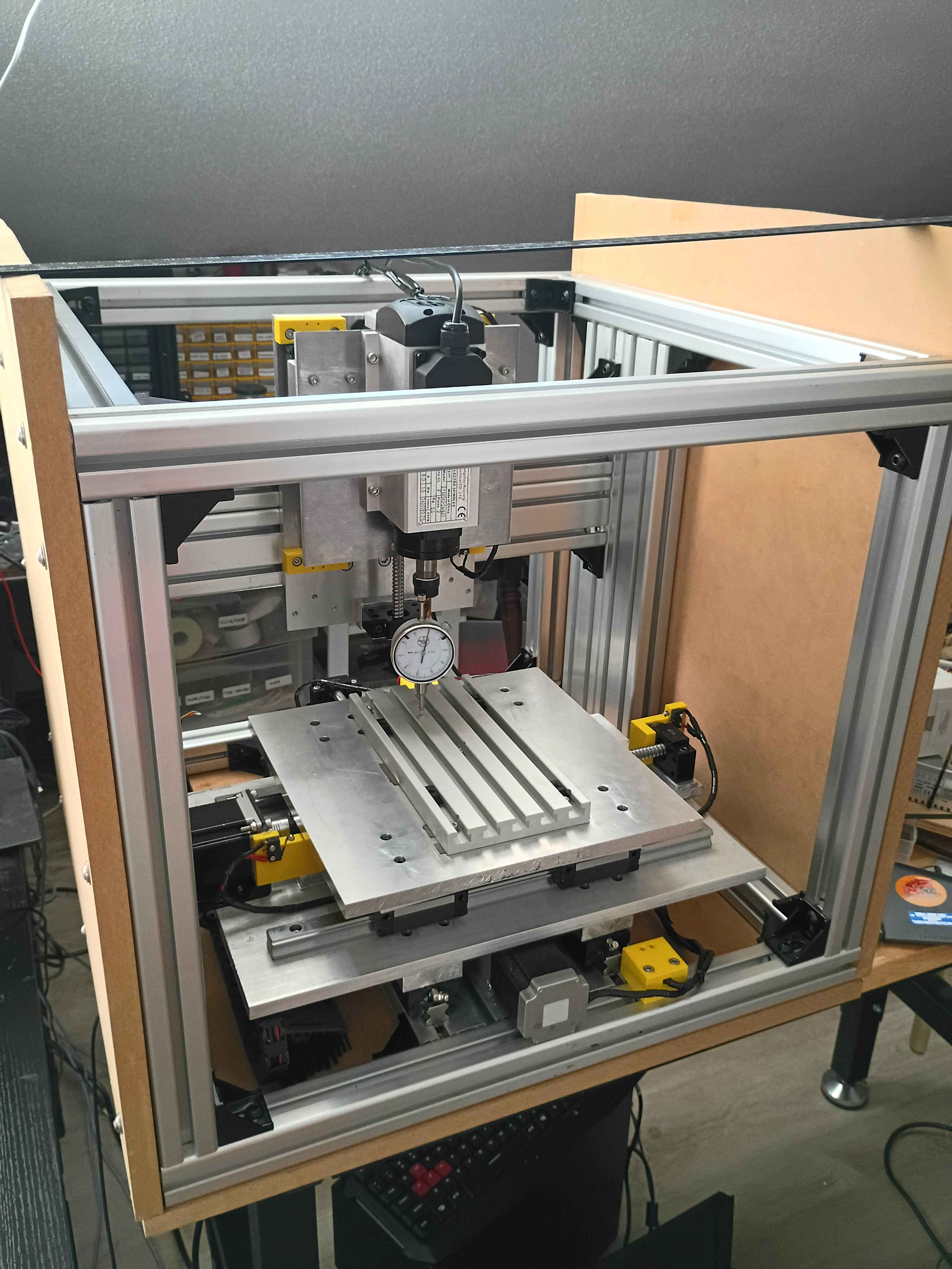
Insert dial indicator into spindle using a 10mm drill bit as an adapter. Determined that the y axis was tram within .0005" and the x axis was tram within .008" over 8 inches of travel. Cut some .001" strips of stainless steel and inserted 4x at the middle of the T-slot fixture plate and 8x at the end, reducing the tram error to less than .0005". Still need to determine if the T slots run truly parallel to the x-axis or not. 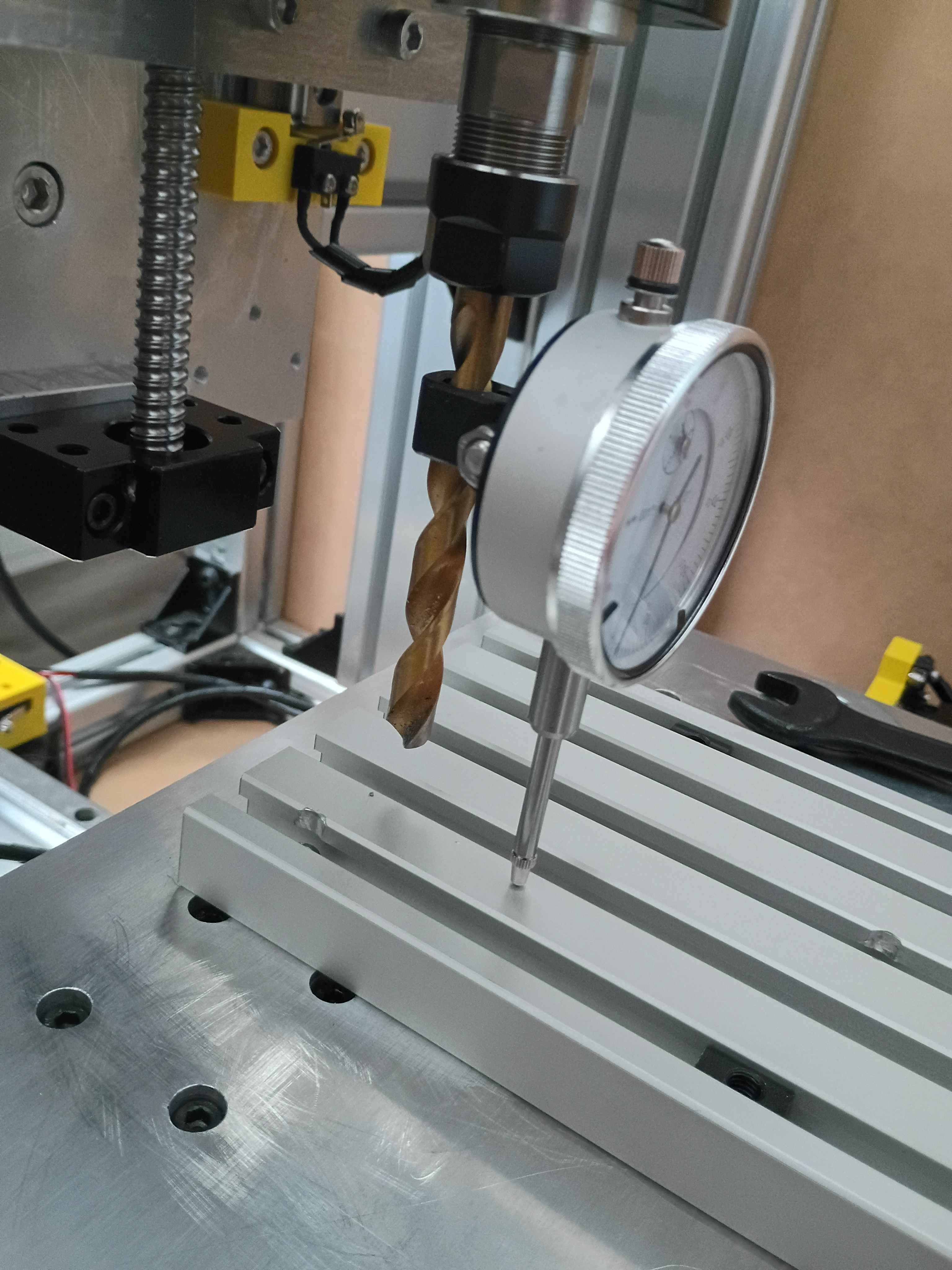
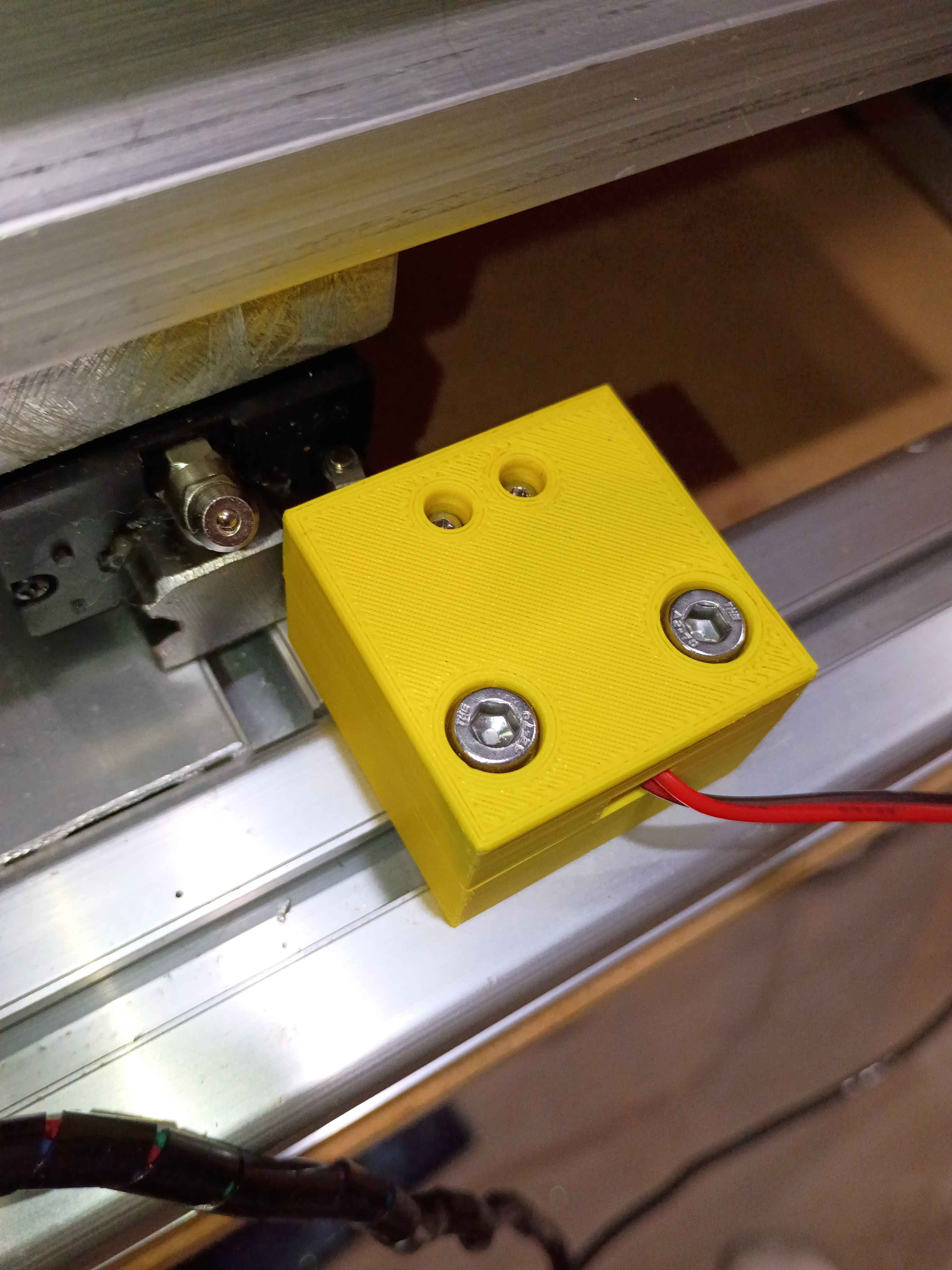
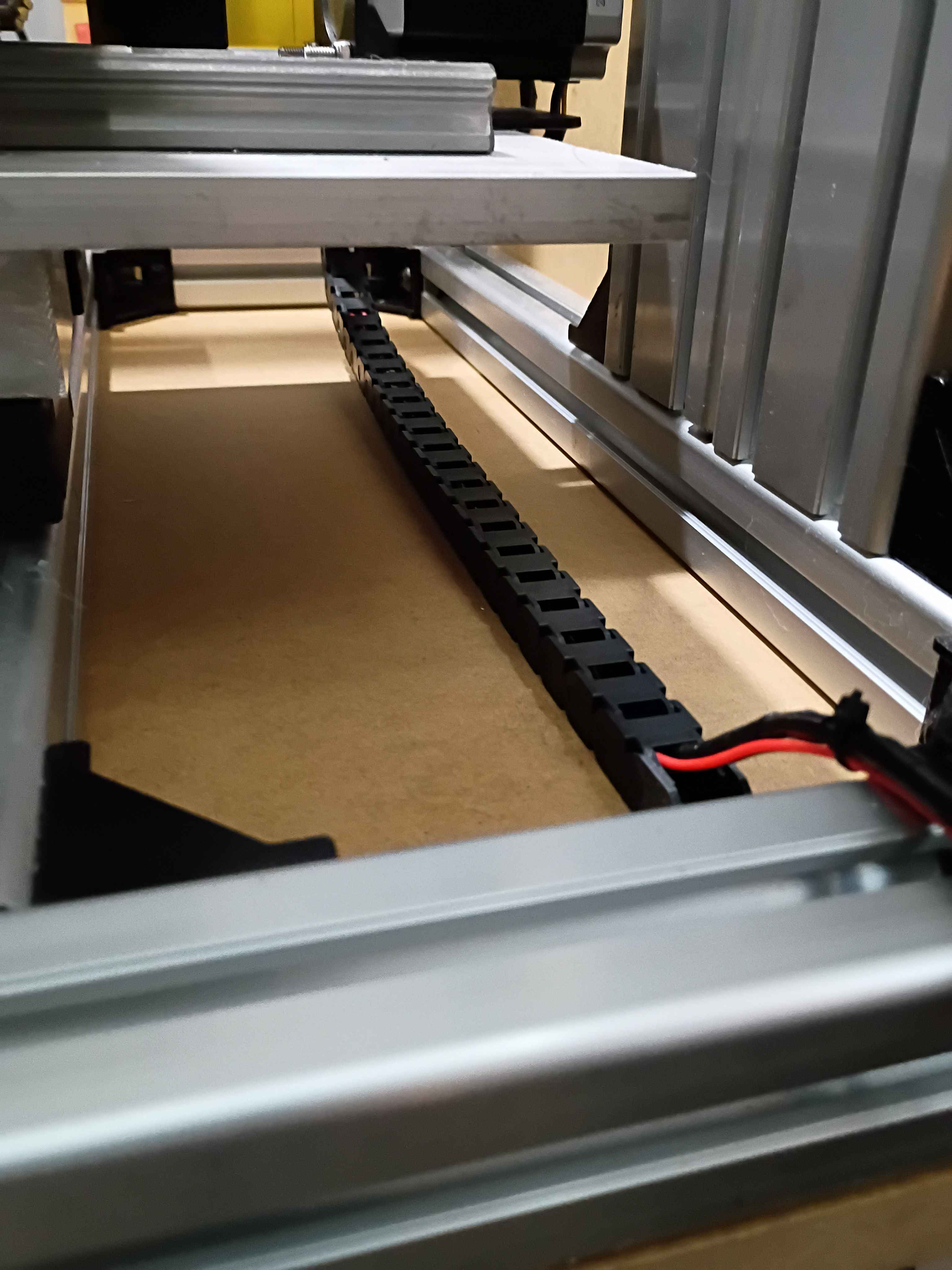
Installed y-axis drag chain. Drilled and installed right side enclosure panel. Designed and printed 2x 2-part limit switch mounts (00001-012 and 00001-013) for the x-axis motion, adding 4 inches of motion to the x-axis. Added some more wire wraps and adjusted some electrical connections. 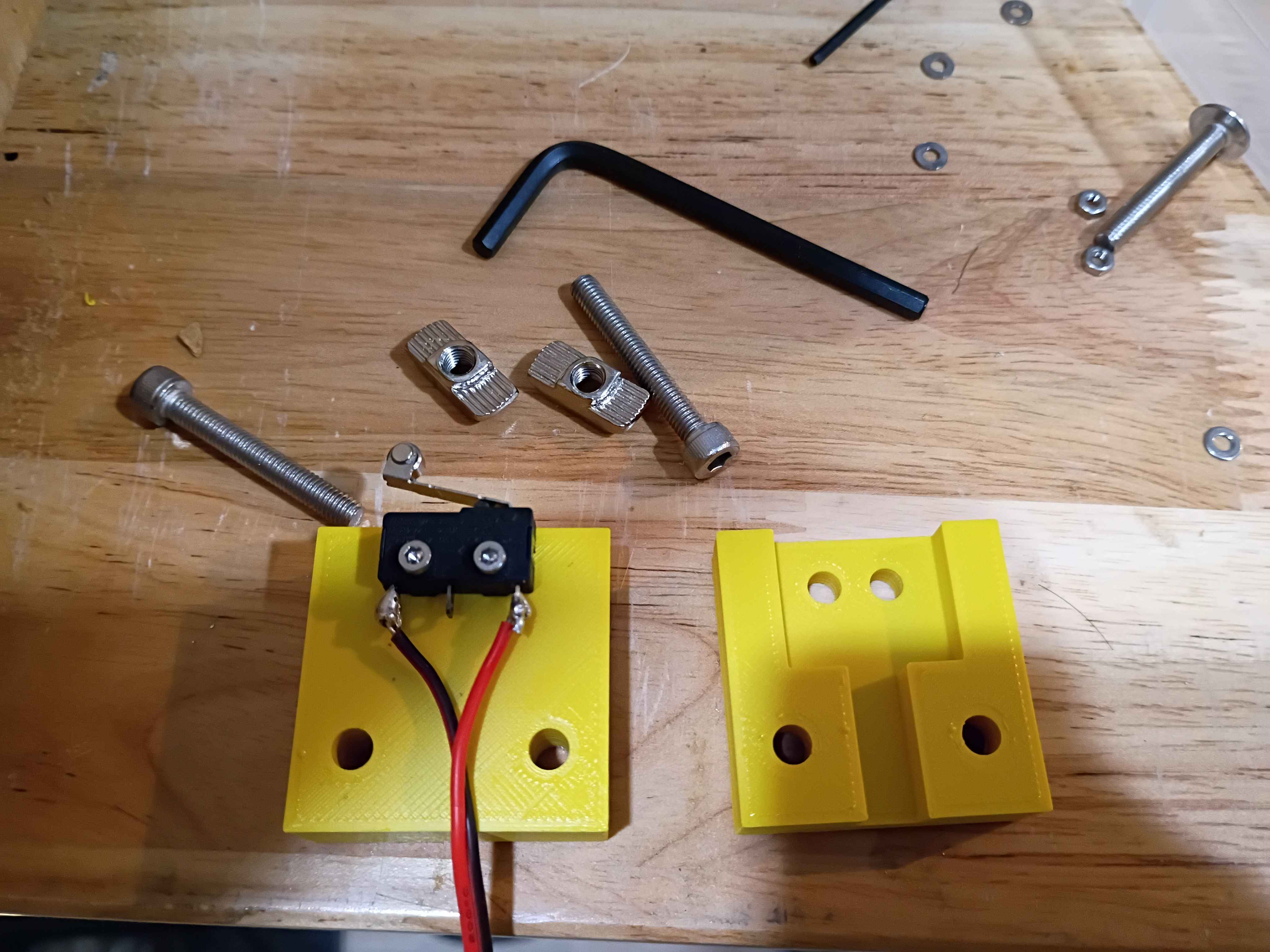
Drilled and installed bottom enclosure panel along with rubber dampener feet. Drilled holes in t-slot fixture plate and drilled and tapped corresponding mounting holes in the xy-gantry plate. Temporarily installed the fixture plate, but it will need to be trimmed with shims. 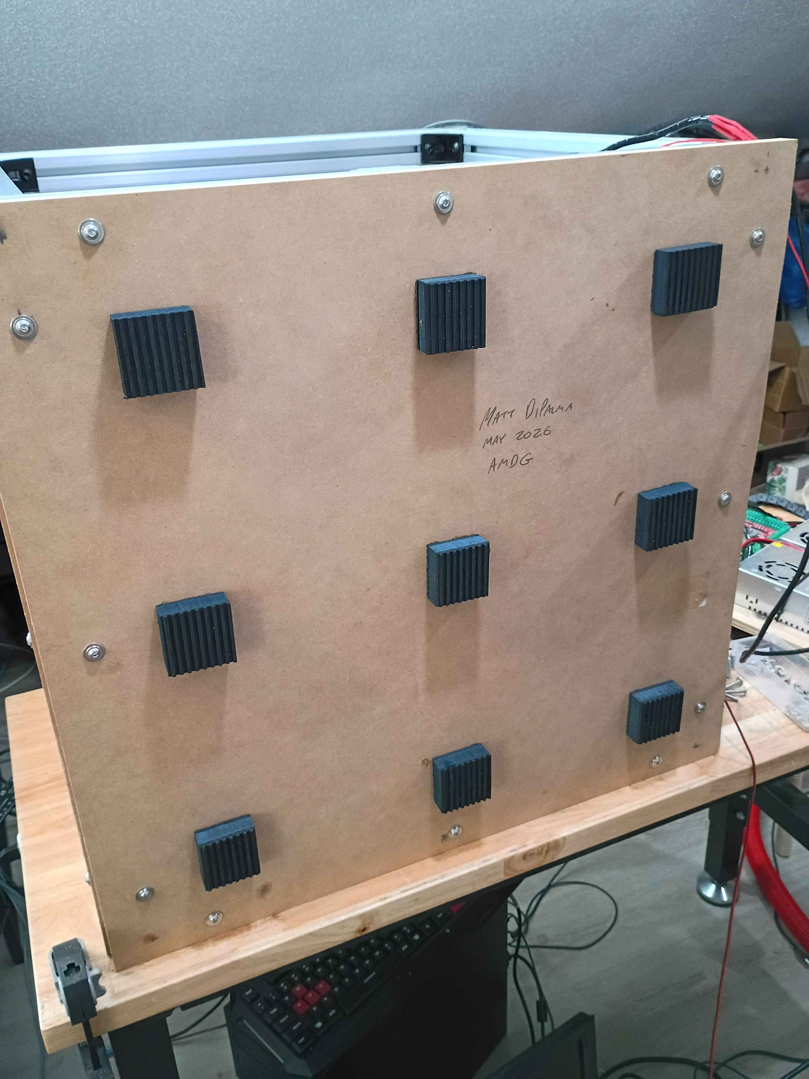
After a client expressed interest, took inventory of old XSD (Cross-Section Development) MATLAB code, and updated the computation of the local inertias using the shoelace formula. Migrated the code to the Marian Scientific repositories.
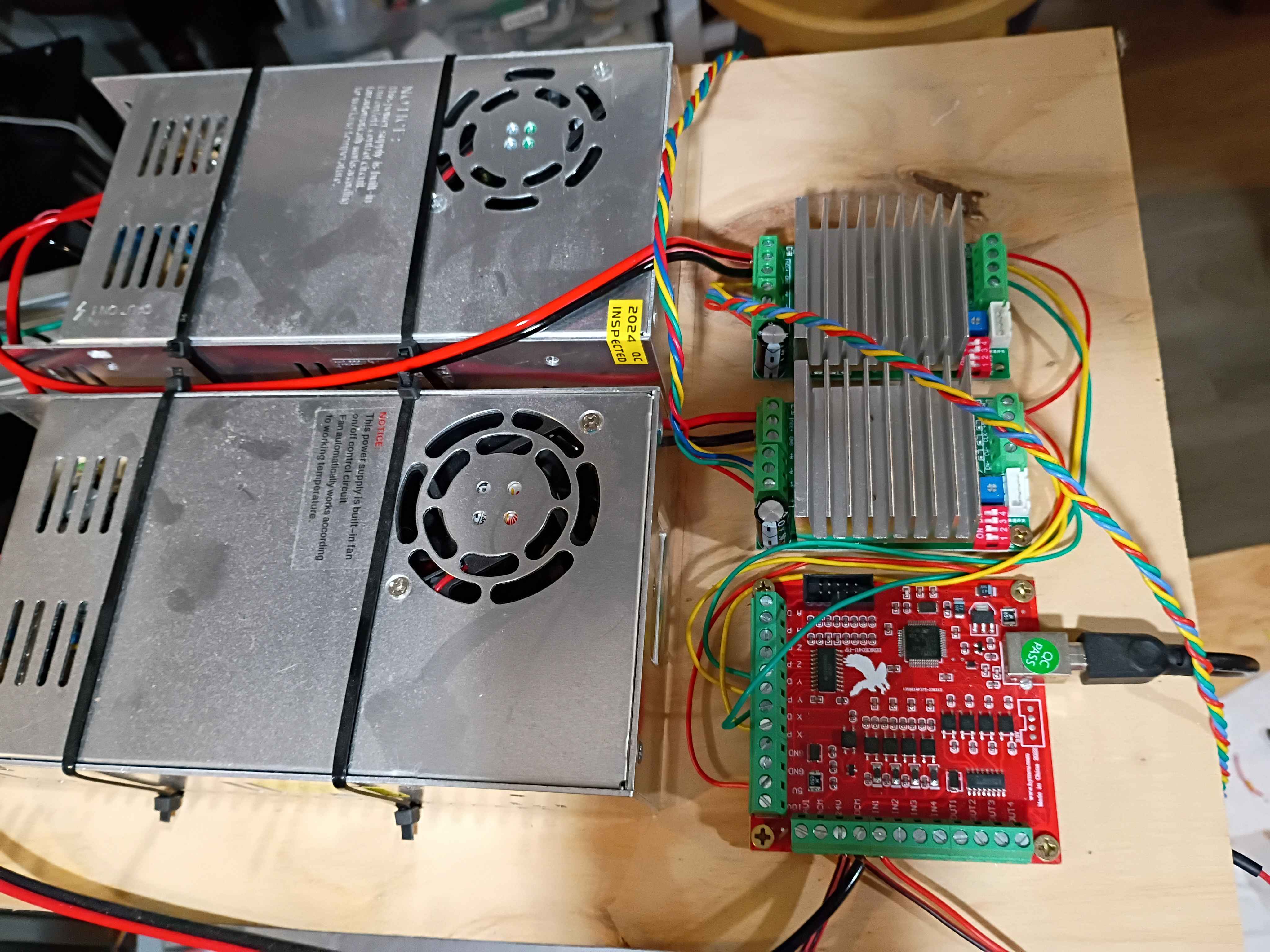
Got CNC to run gcode for a CAM path generated in FreeCAD See video of it running. Had to adjust the step count to 800 steps per mm for all axes because the drivers are set to 16x microstepping and the 1204 ballscrews have 4 mm pitch and the steppers generally have 200 steps per revolution so (16*200/4=800). Also wrapped the stepper lead wires in protective wire wrap. 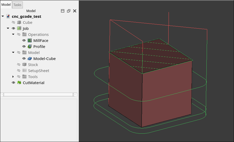
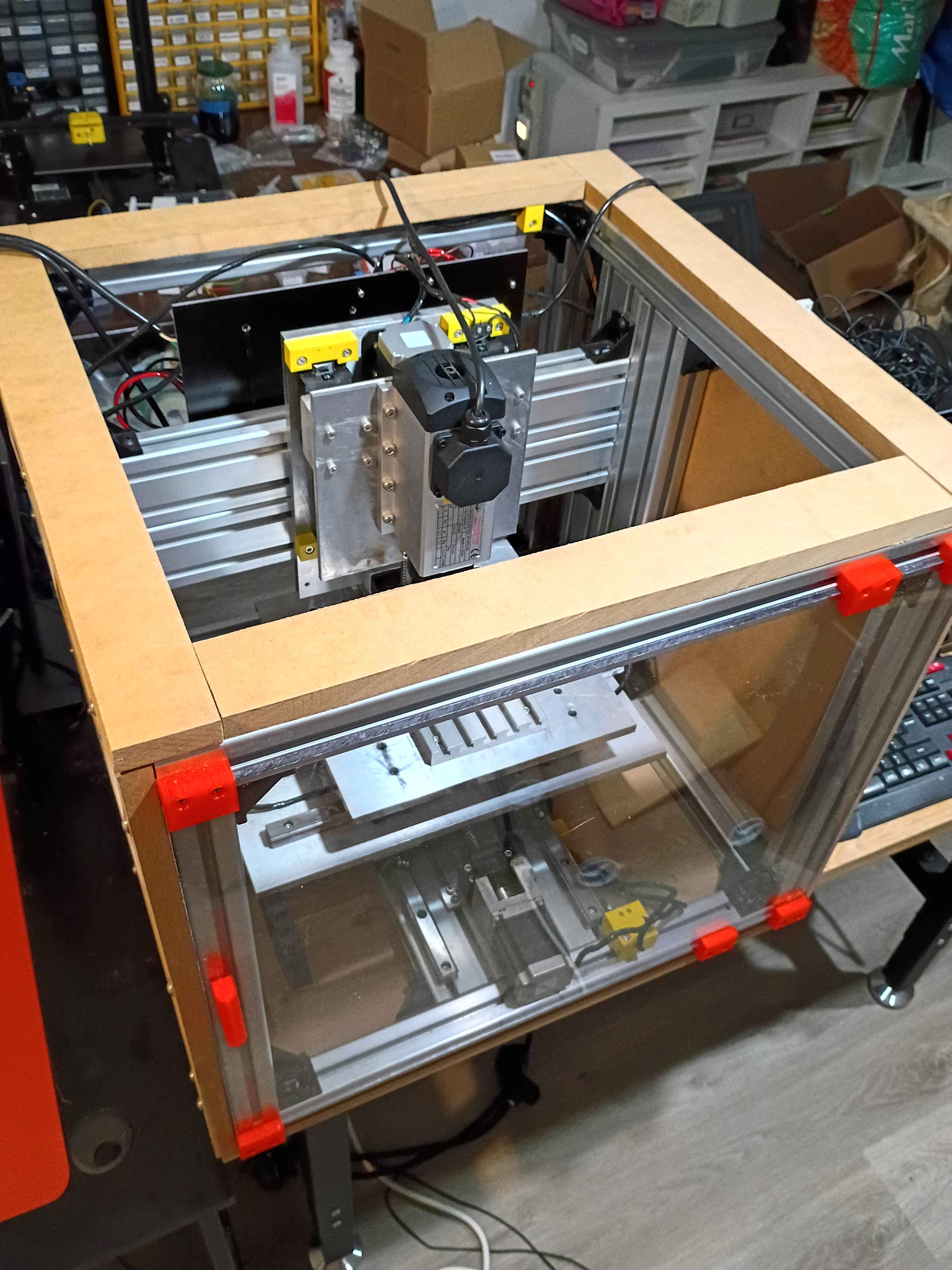
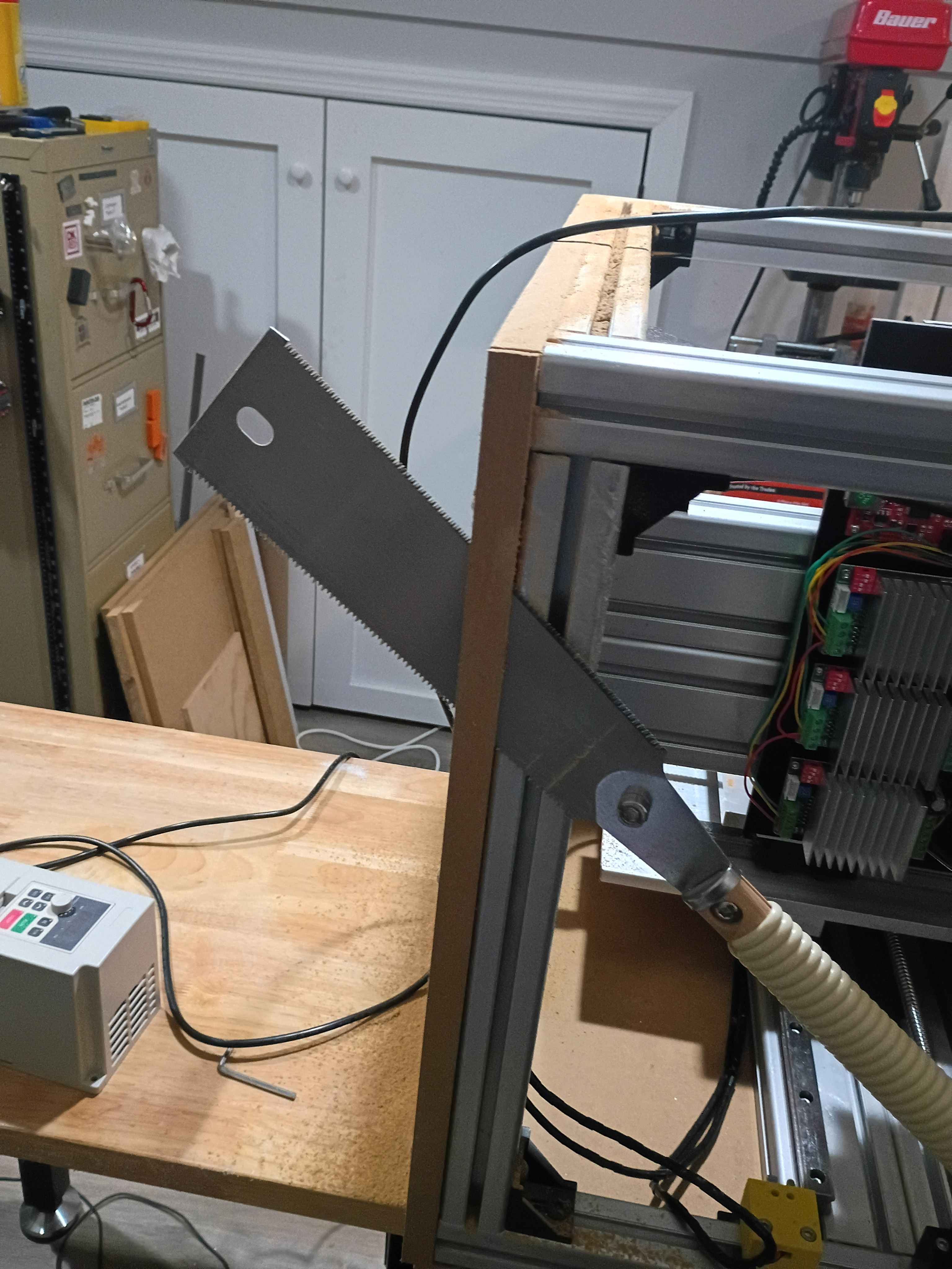
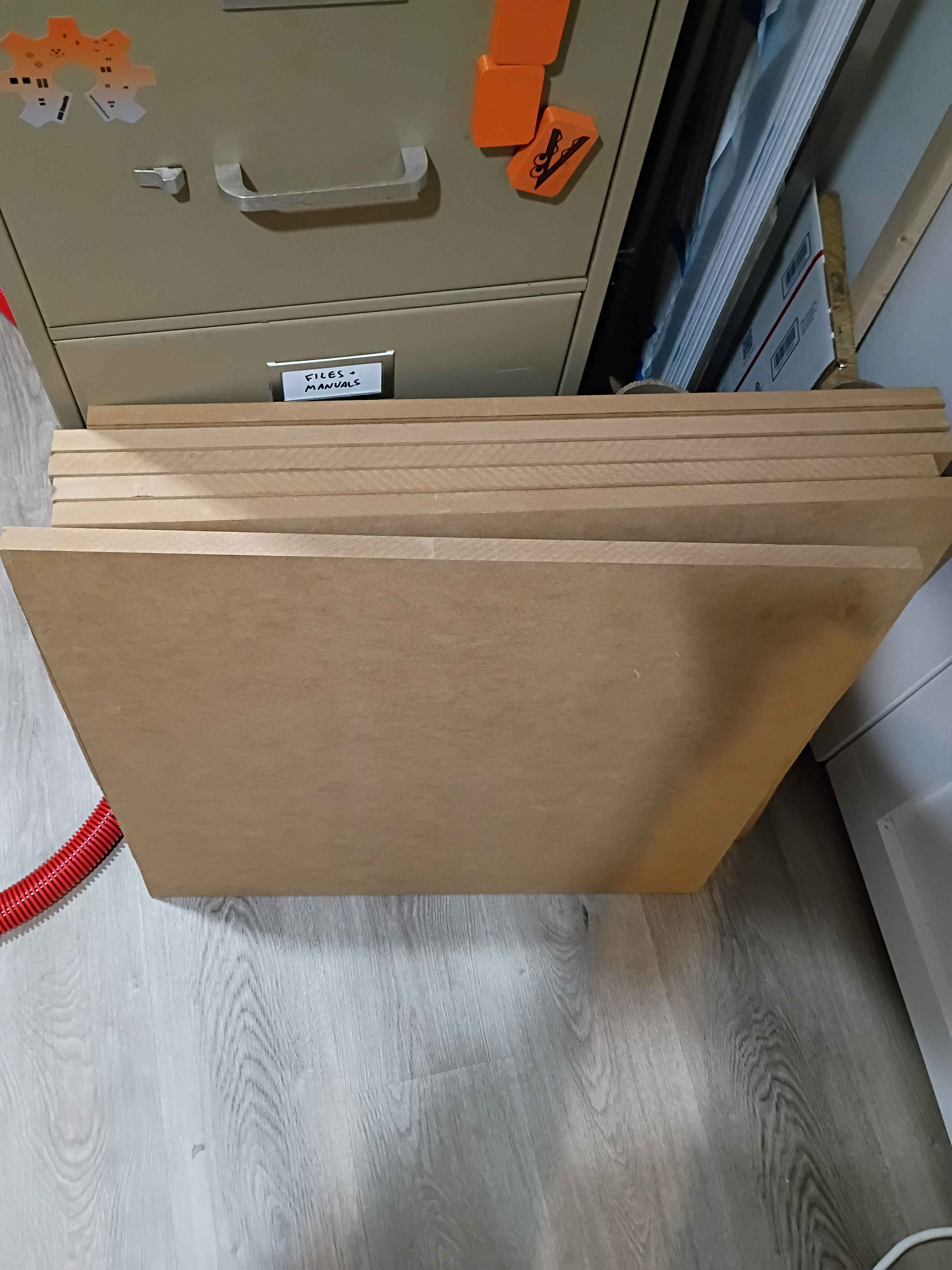
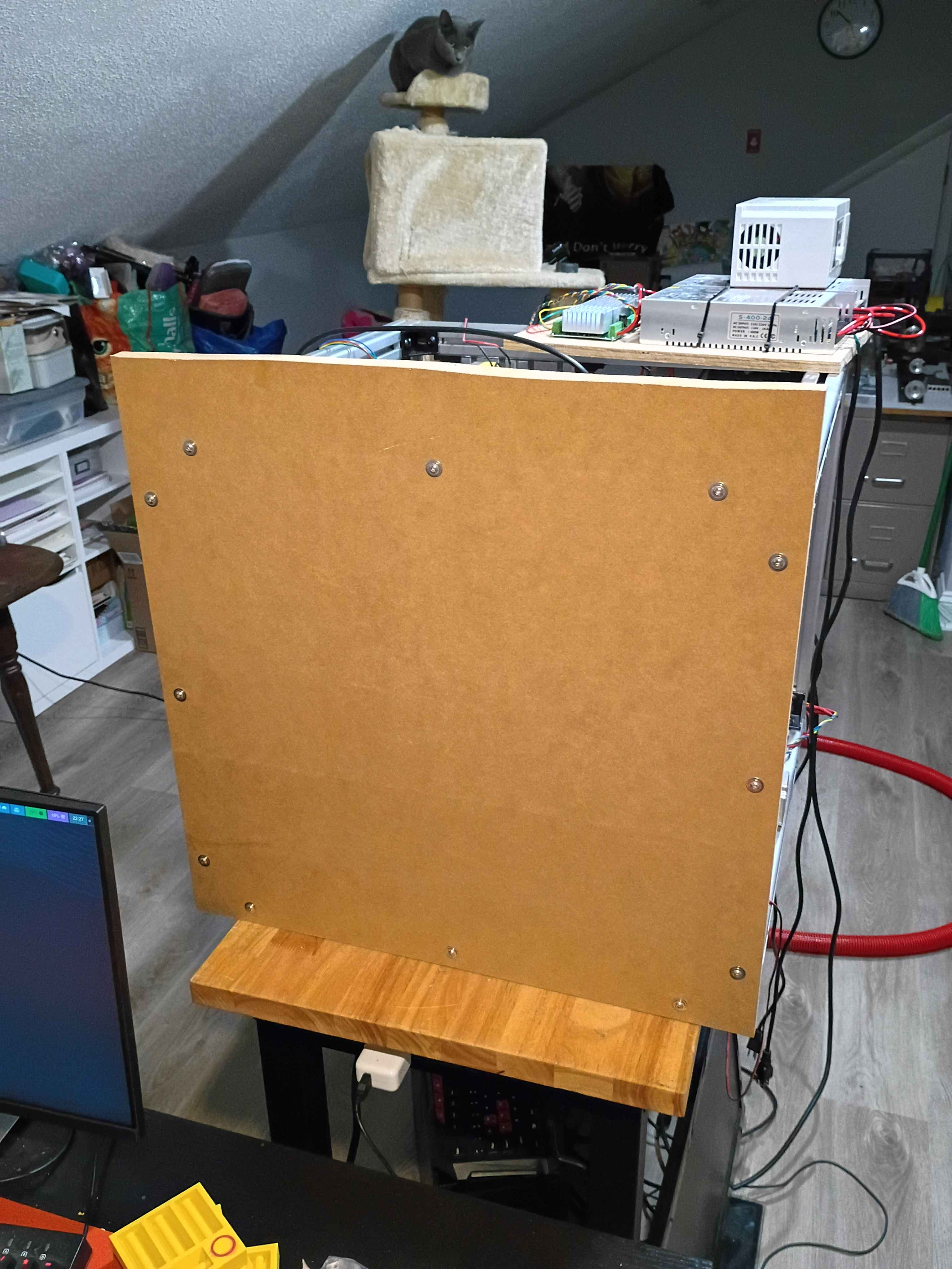
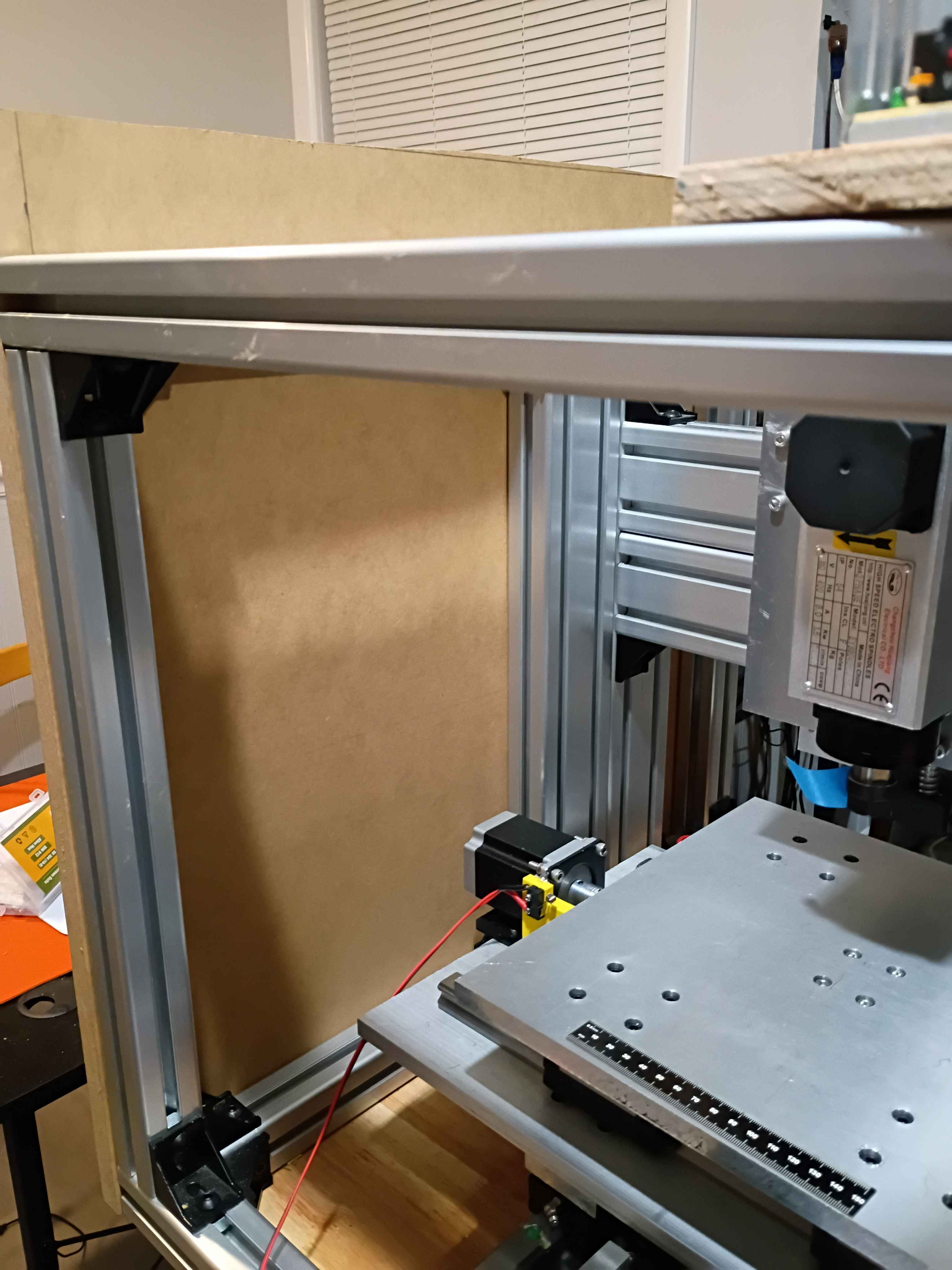
Finished sawing all 6 panels for the enclosure. Drilled holes and installed one side panel with flange bolts, fat washers, and t-nuts. I decided to put the excess material on the top to make some little container to hold things up there. I am holding off on doing the remainder of the enclosure until I know it works. 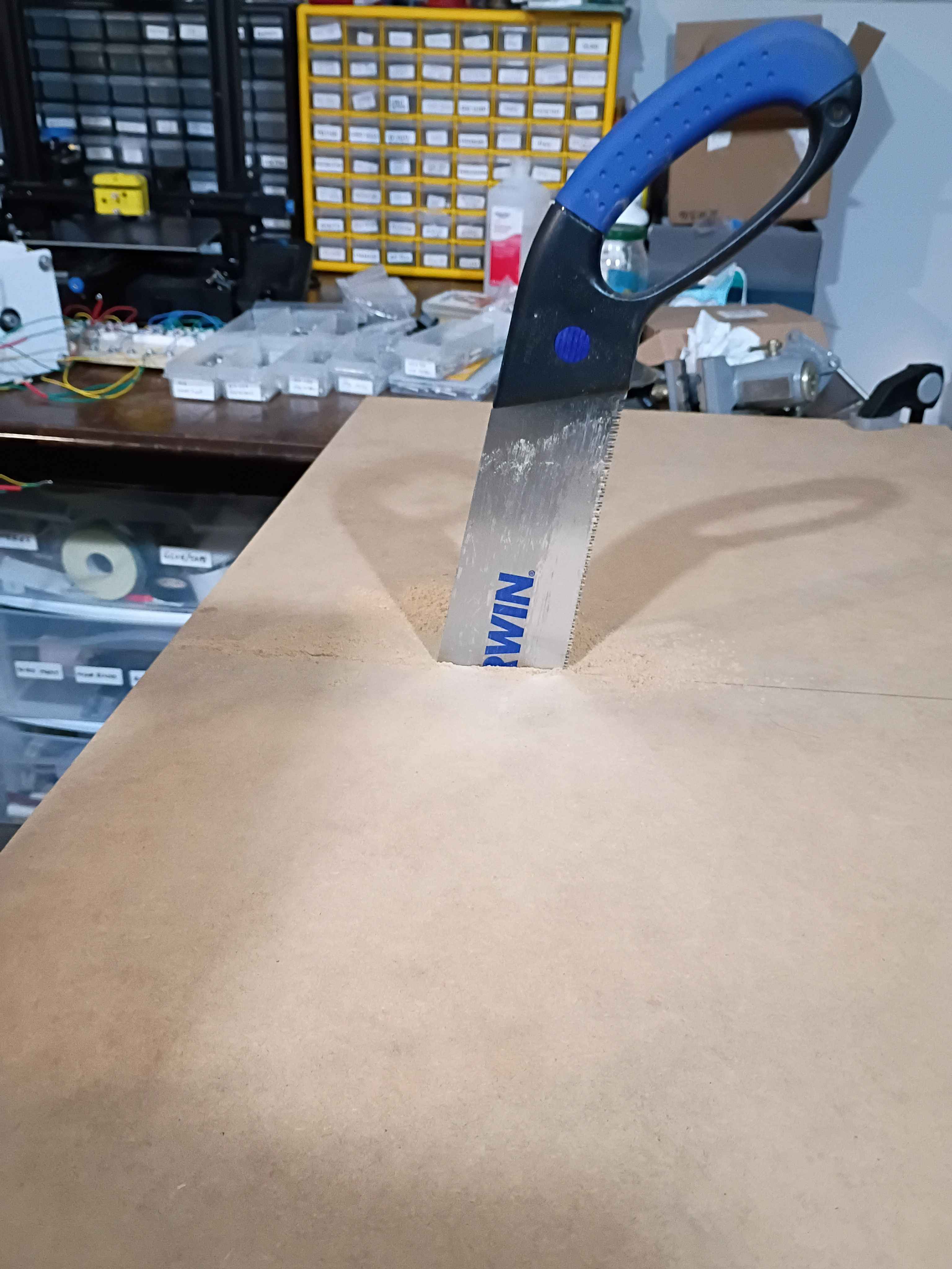
Bolted up the rest of the z-axis linear motion components including the spindle, configured all the electronics and software, and did a successful dry run. The stepper driver board that I had installed was bad, but thankfully I had an extra. In the future, the x axis motion can be extended slightly, and the z-axis downward limit switch is around 45mm beyond the feasible range of motion, so if that is to be used, some alternate stoppers and limit switch mounts will need to be printed. 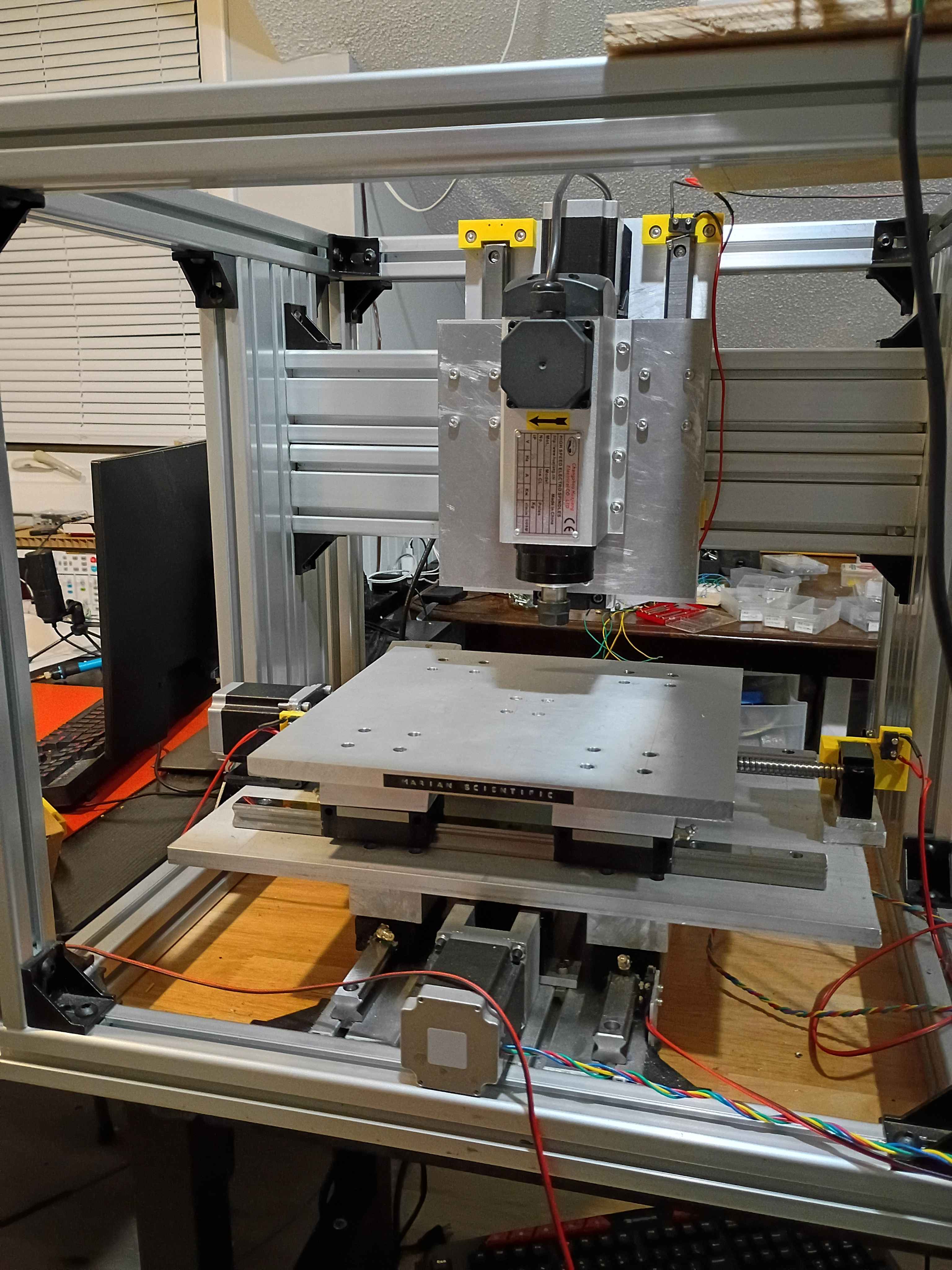
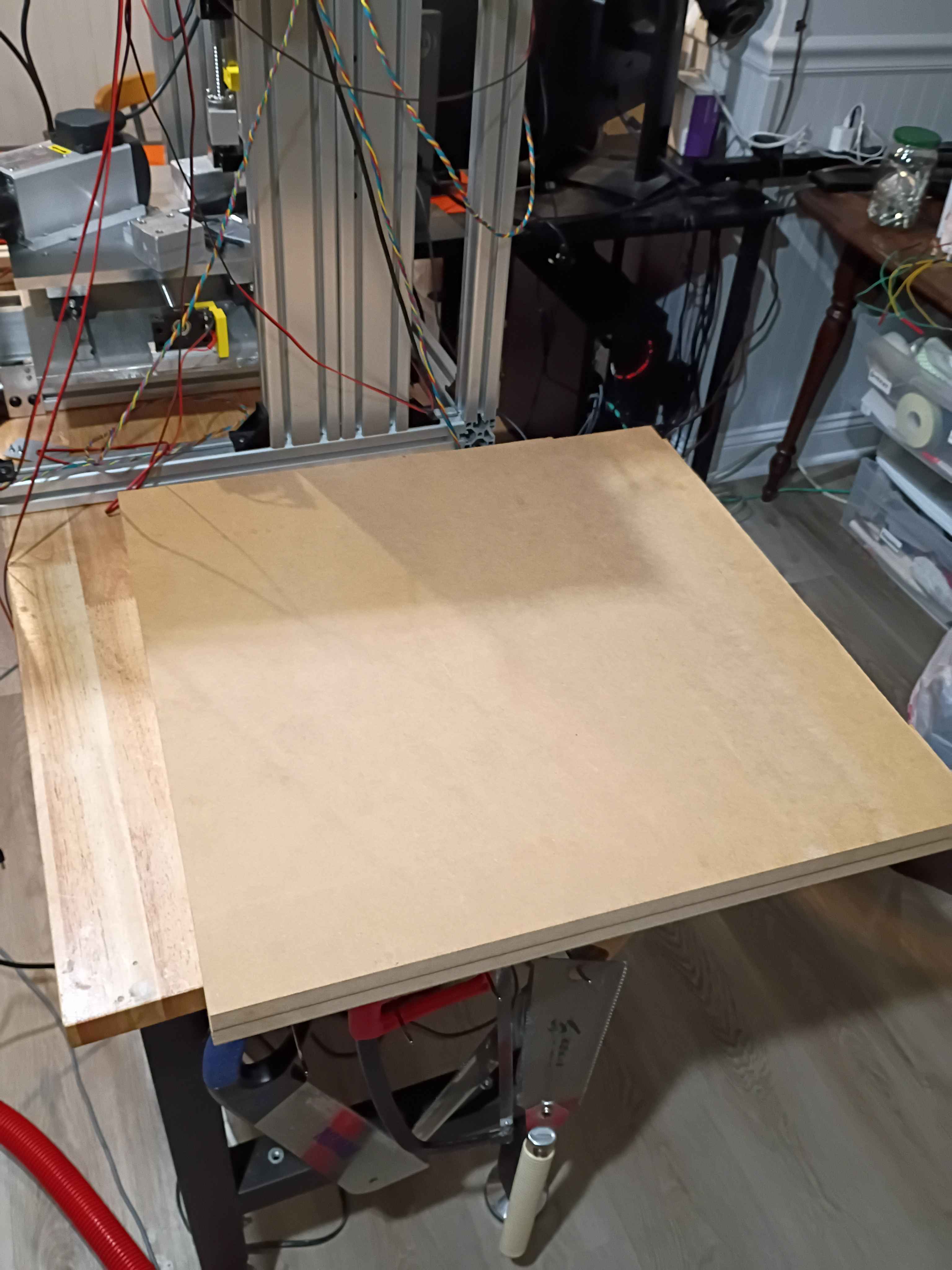
Purchased and cut two 24x~24x3/4" panels from MDF for the top and bottom enclosure walls. Widened the holes in 2 of the spacers and did a dry fit of the Z mount plate. I will probably need washers or something or to file down some of the stepper bracket, as they slightly interfere when the carriages slide upward enough. 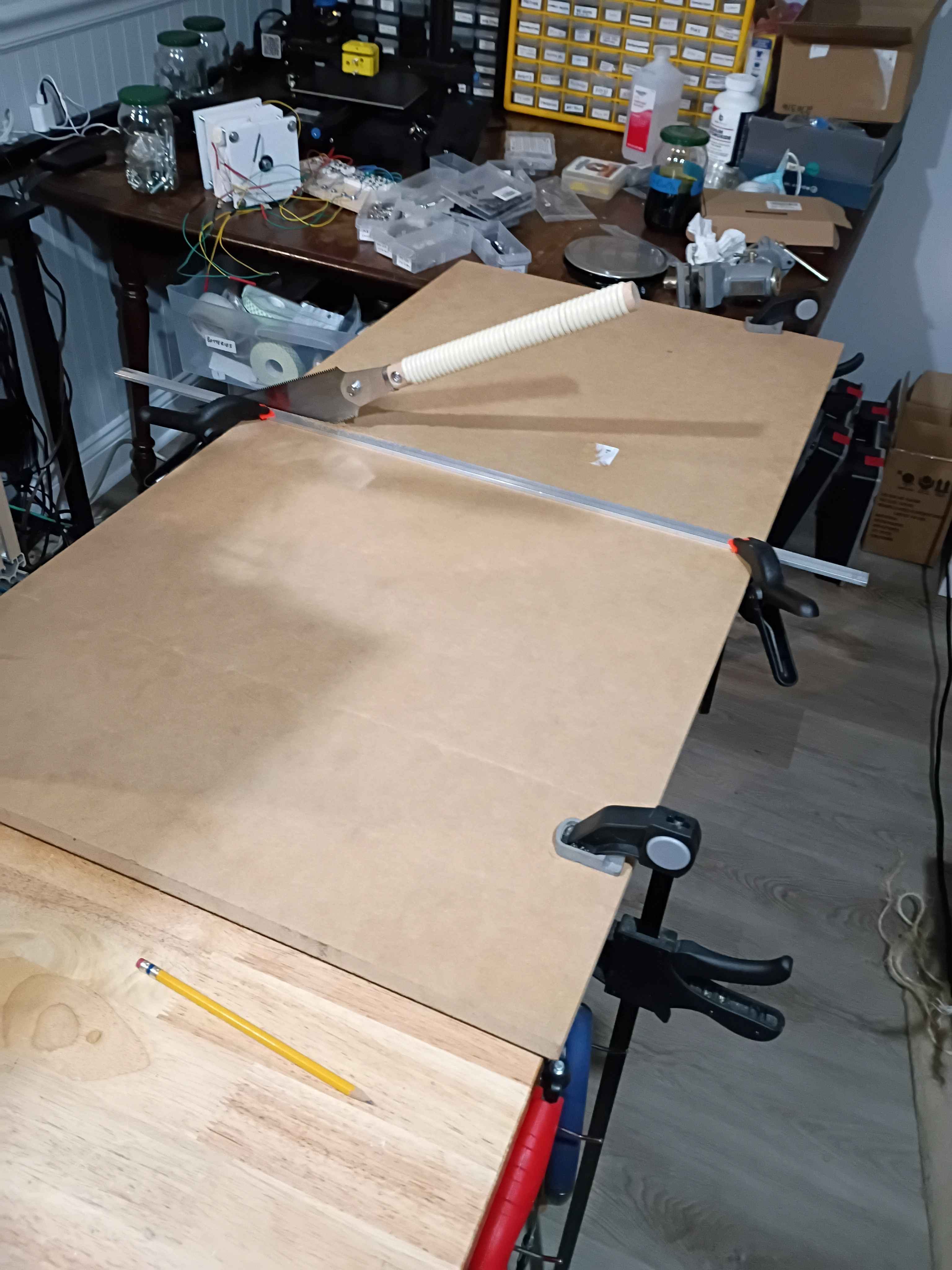
Cut and drilled last spacer. Marked (by printing a template) a drilled the Z-axis mount plate. Realized an earlier carriage spacer had holes that were not straight thru since the part was 2" thick and drill bit deviated as it cut, so I opened those 5.5mm holes to 8mm. Connected all Z-direction motion wiring. Used a power drill to coil the stepper motor lead wires (very cool). Also wired the VFD and spindle motor and did a quick test. 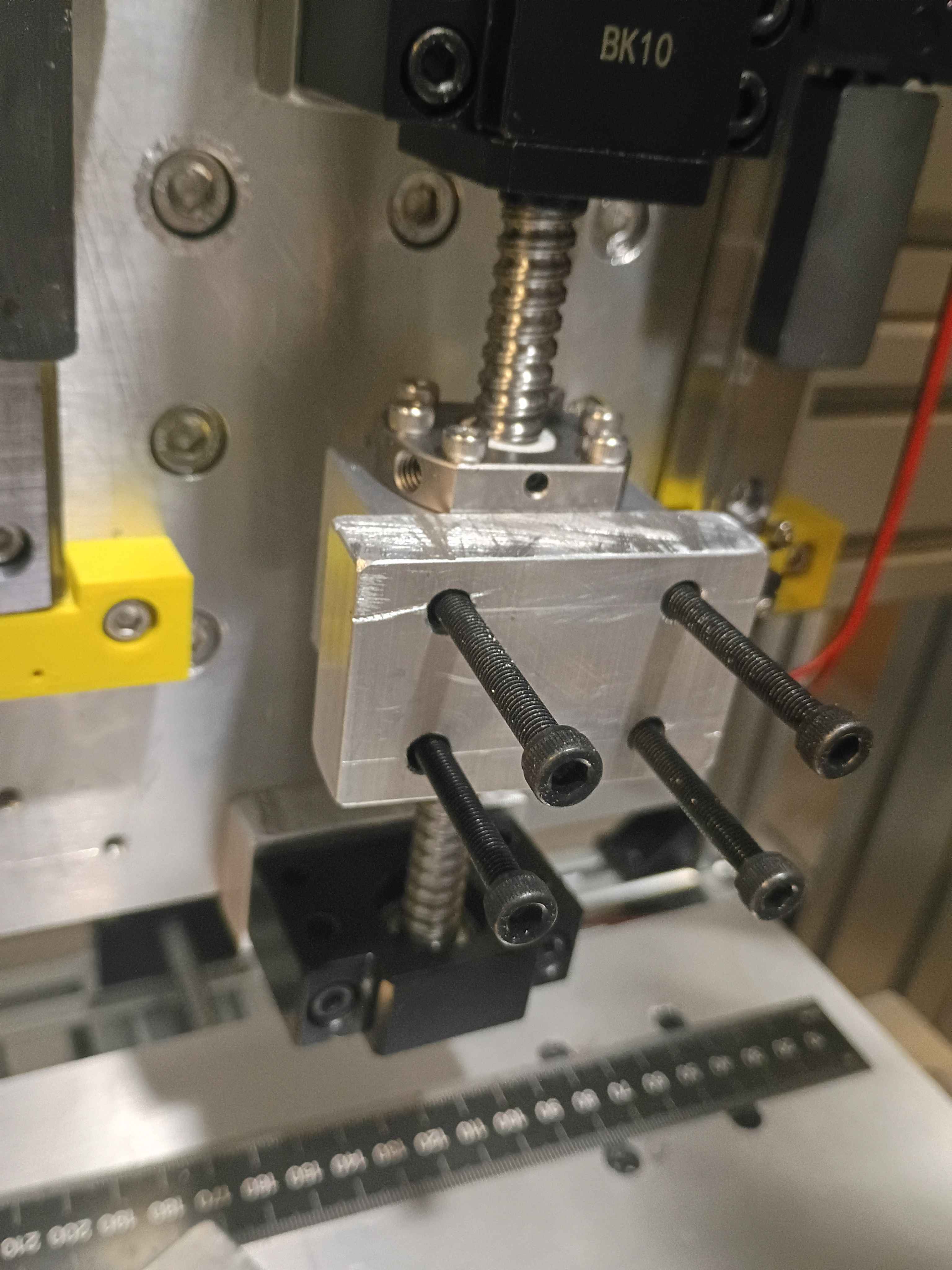
Added DOCTYPE callout to HTML pages, fixed a bug with project links from author pages, and manually corrected some image and link issues for some of the earliest journal entries.
Added manual backup script from my personal computer to archive important Mary-Bot and other website-related files.
Fixed bug in journal entries not incrementing. Cleaned up image naming convention and JSON database old .INI converted entries missing the last character. Tried to update the cache lifetimes of images for performance, and converted all the thumbnail images to WEBP for efficiency (major task). 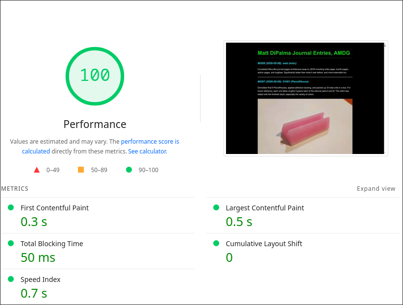
Completed Mary-Bot journal pages architecture swap to JSON including index page, month pages, author pages, and bugfixes. Significantly faster than what it was before, and more extensible too.
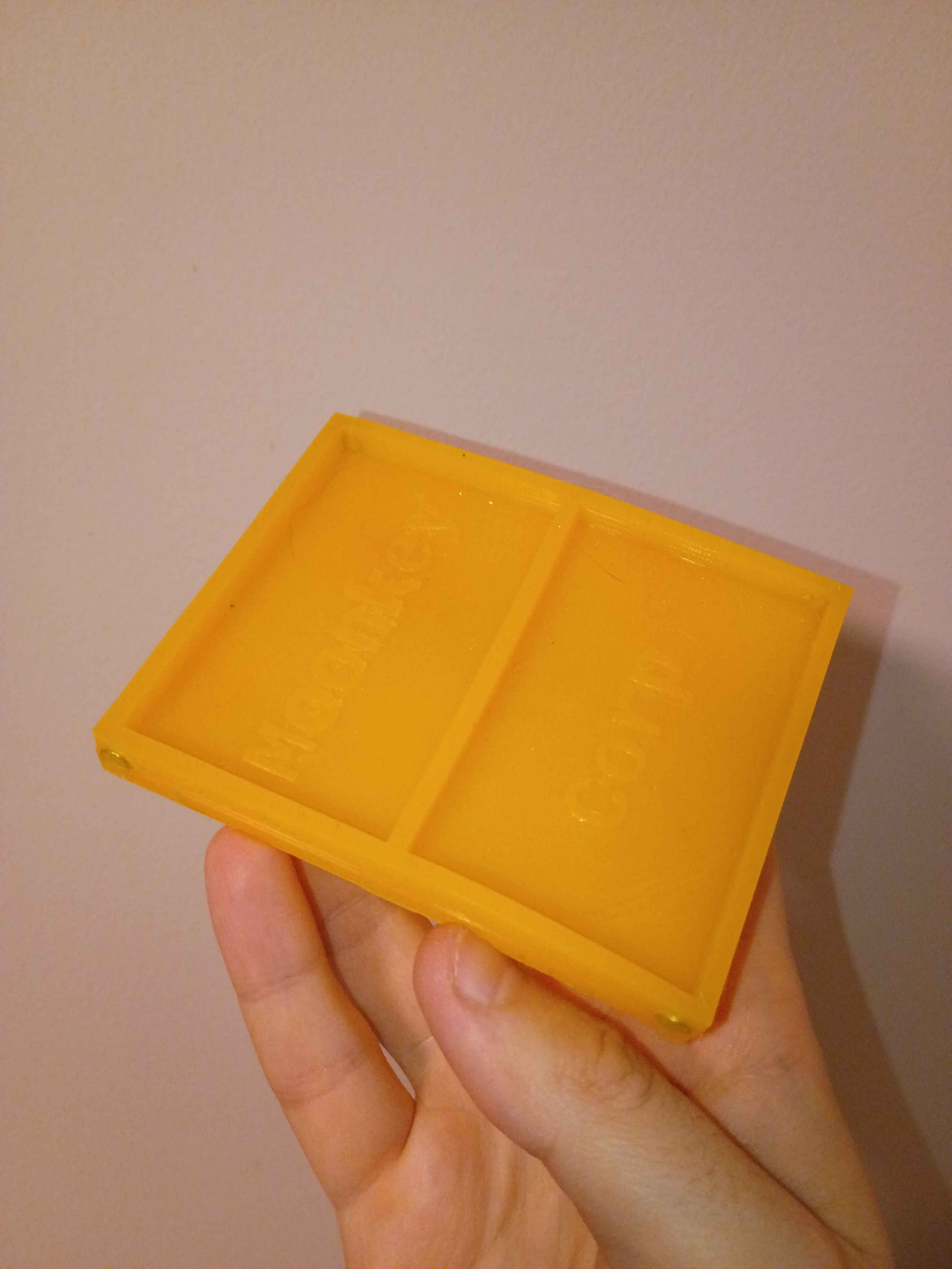
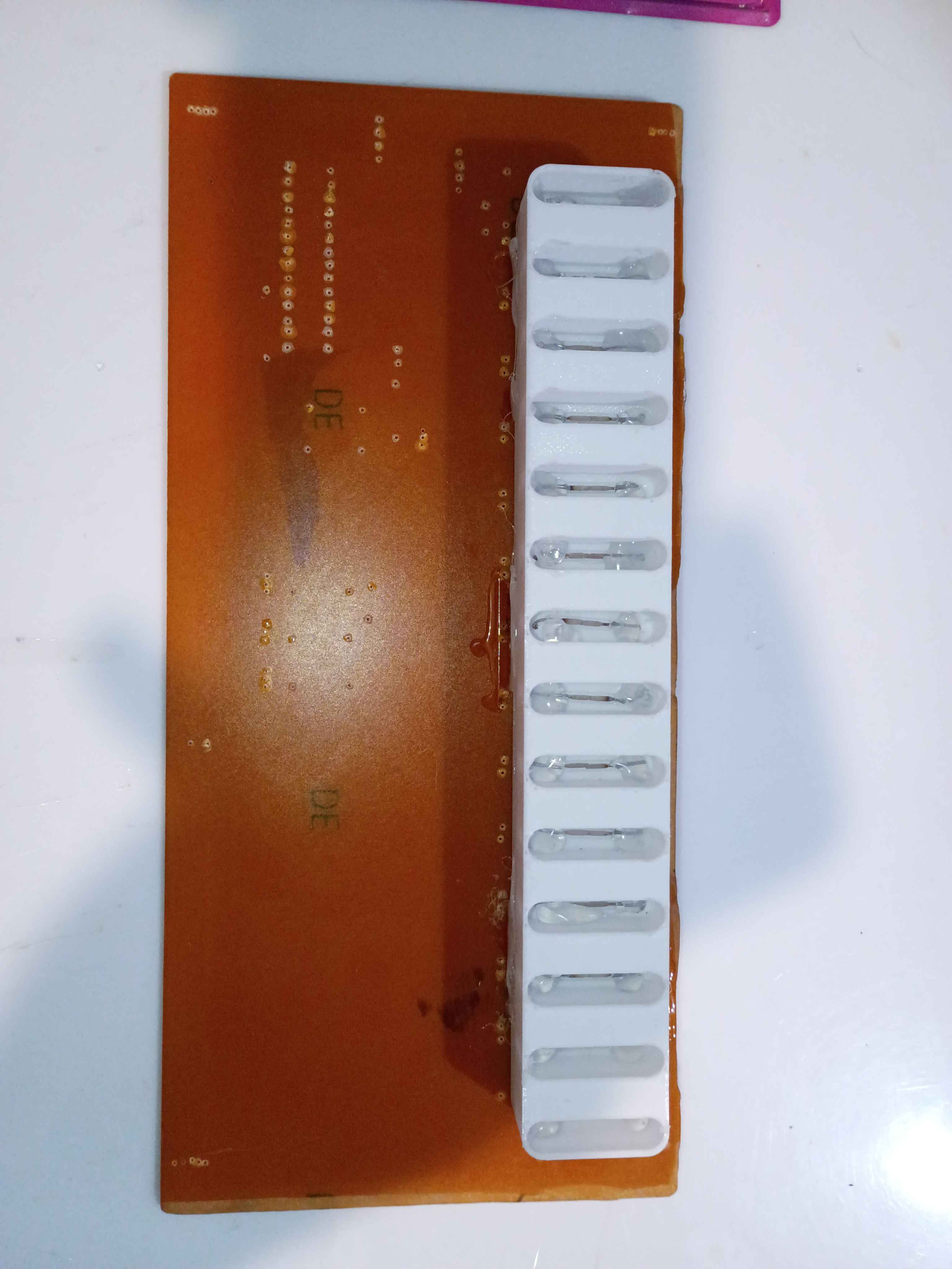
Demolded final 9 PencilHouses, applied adhesive backing, and packed up 33 total units in a box. For future reference, each unit takes roughly 5 grams each of the silicone parts A and B. The client was elated with the finished result, especially the variety of colors. 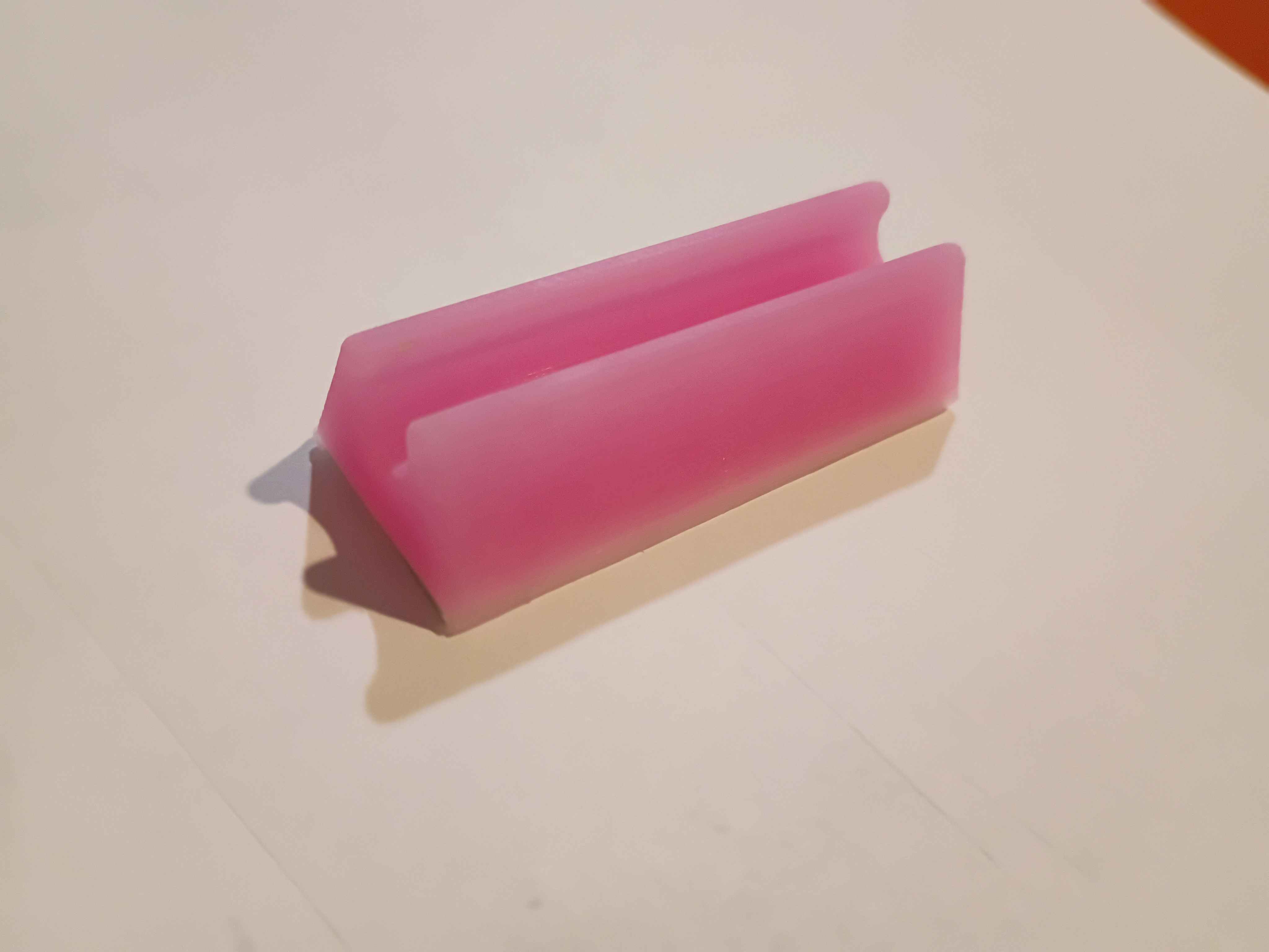
Finished converting journal main page to the new architecture, along with the entire !addproject !deleteproject !listproject setup. Now only the sub-category author and project pages need to be converted. 
Updated journal main index page to read from latest JSON journal entry list. Much faster, but the rest of the website is still under construction.
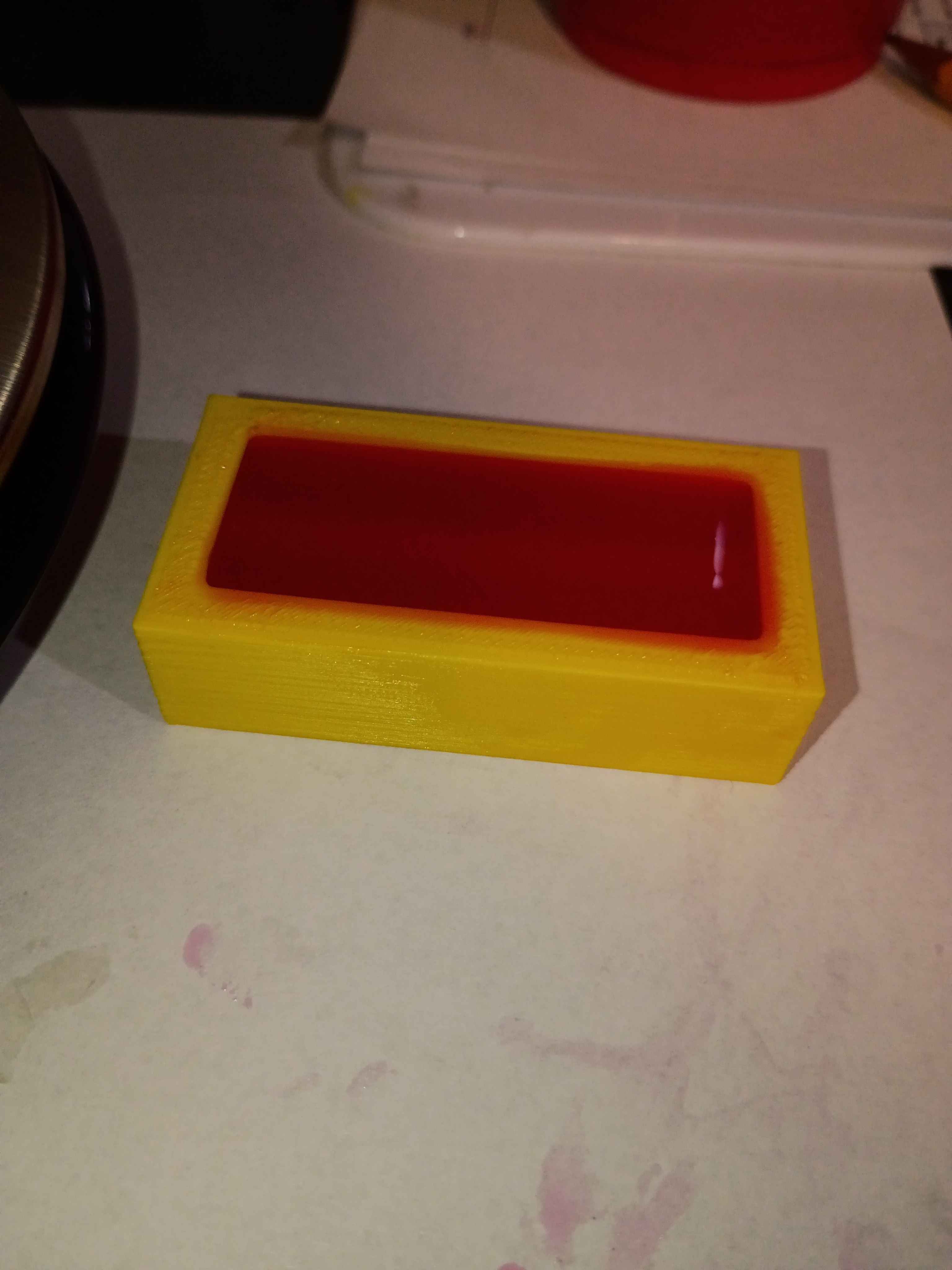
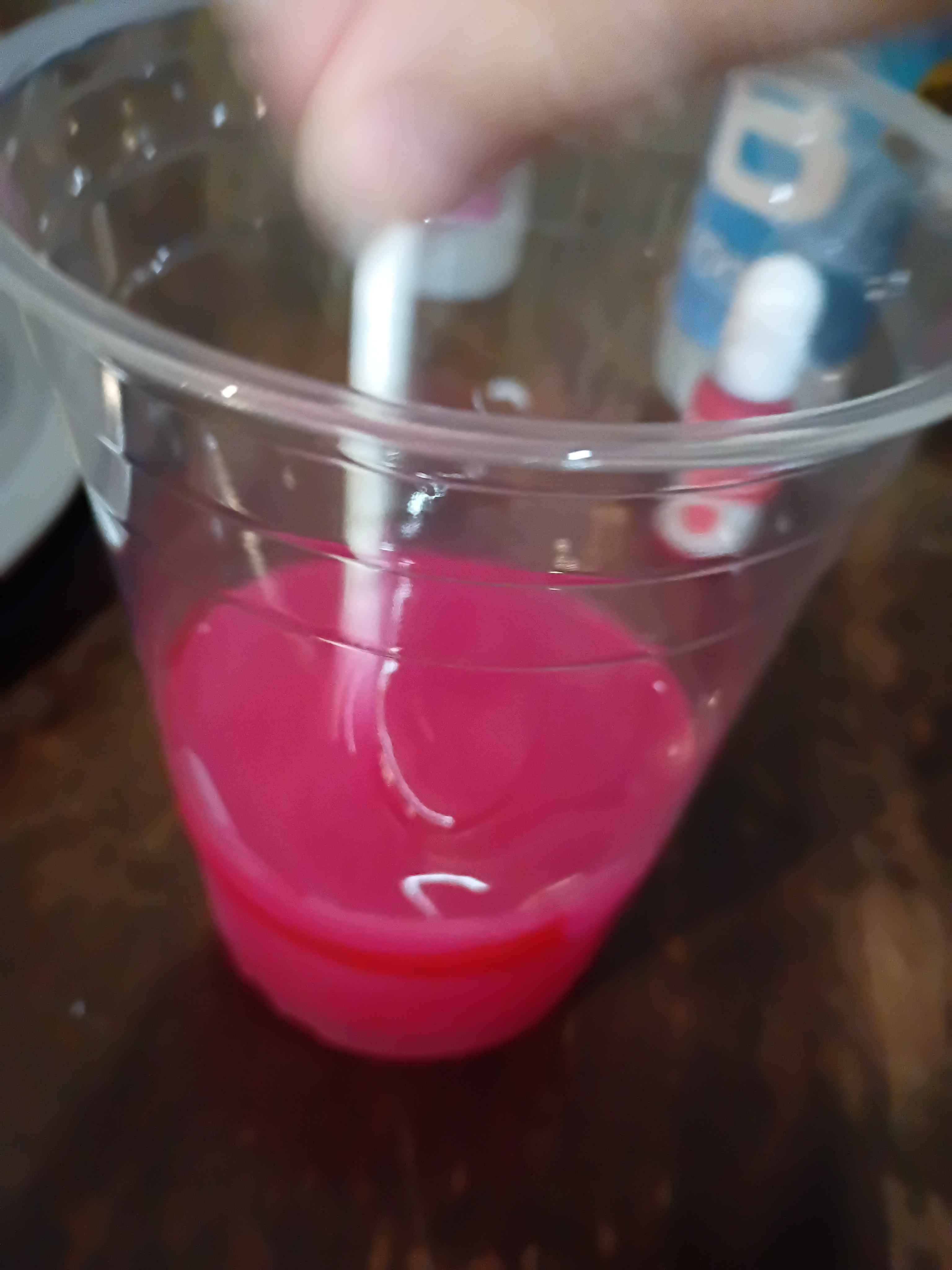
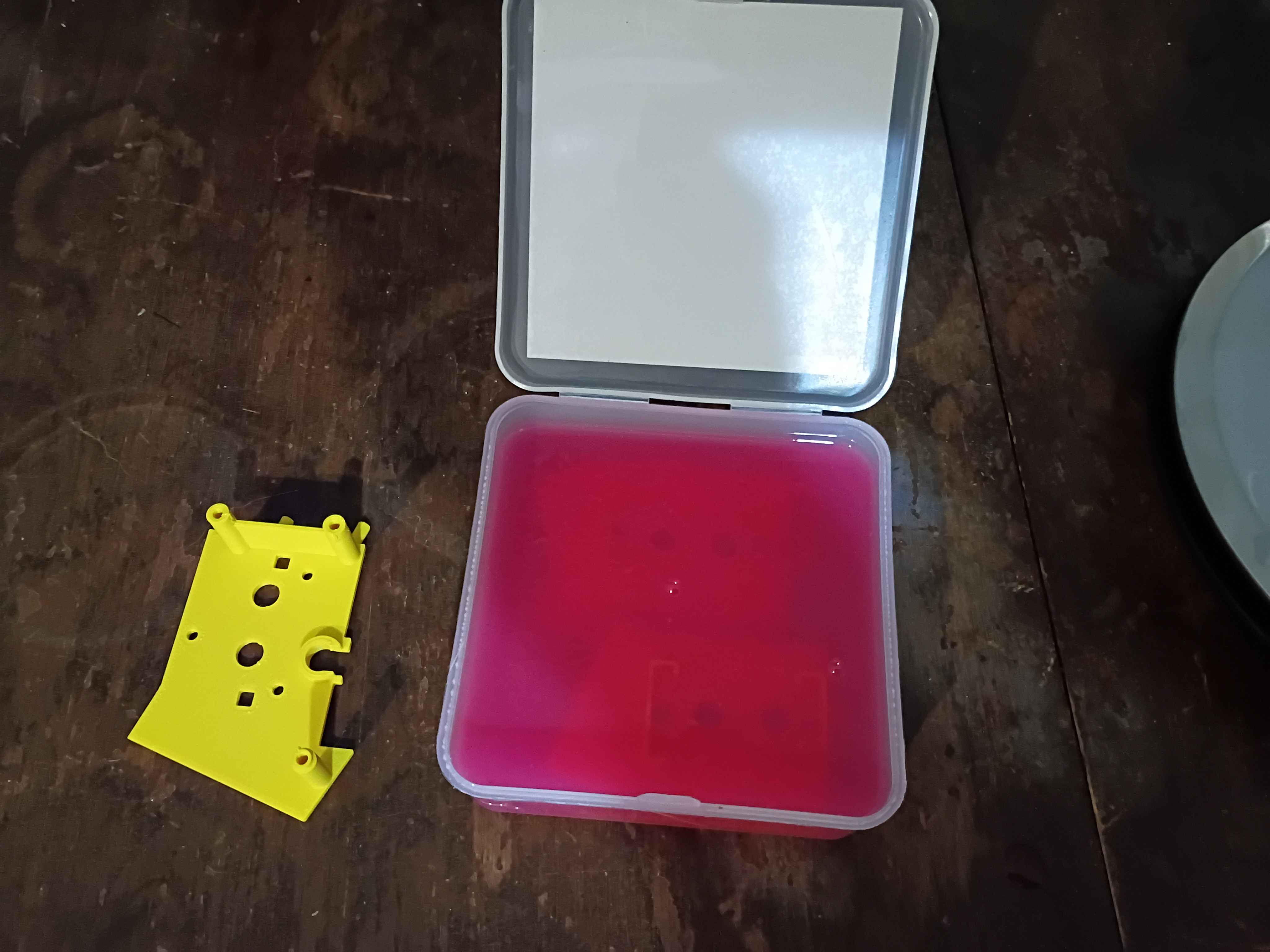
Poured 9 more pink PencilHouses. For reference, the pigment is roughly 5:1 white:red. 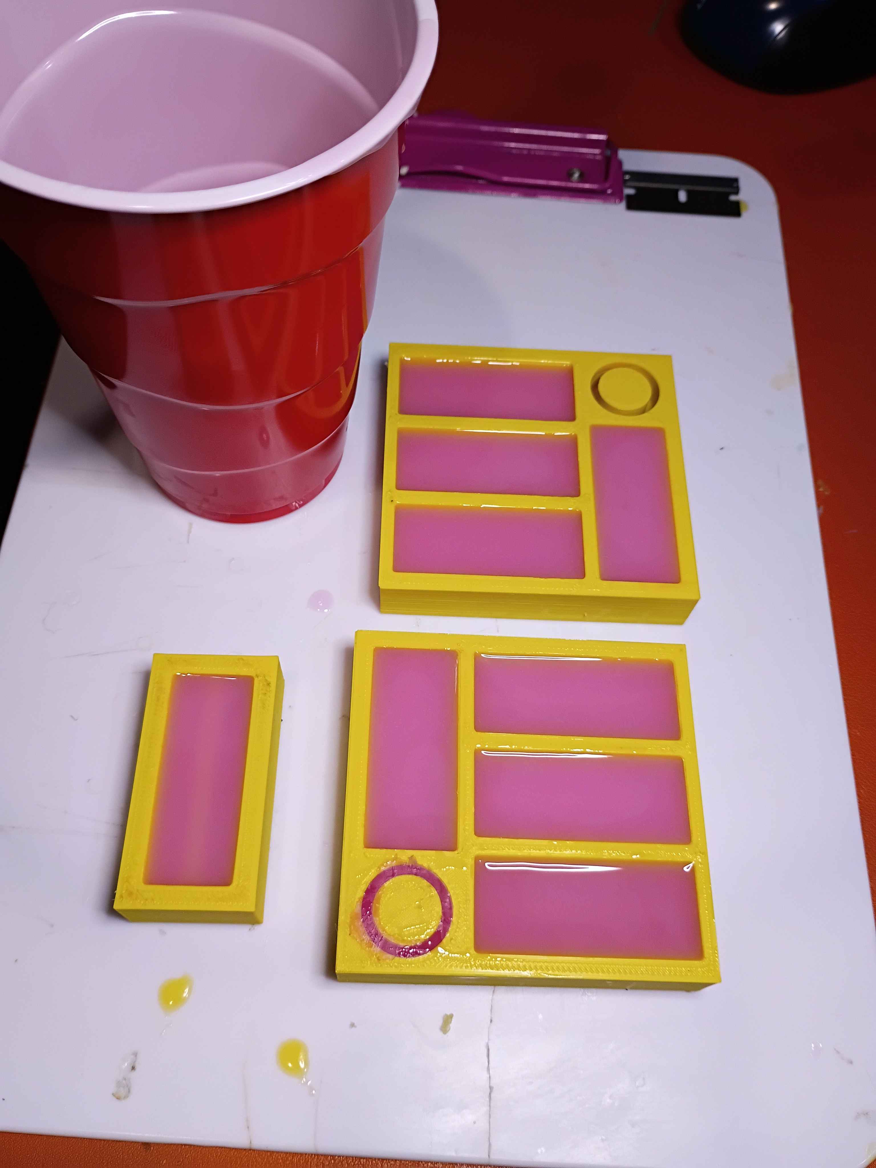
Corrected Mary-Bot logic for depth requirement success checking. Continued to modernize the journal handling code.
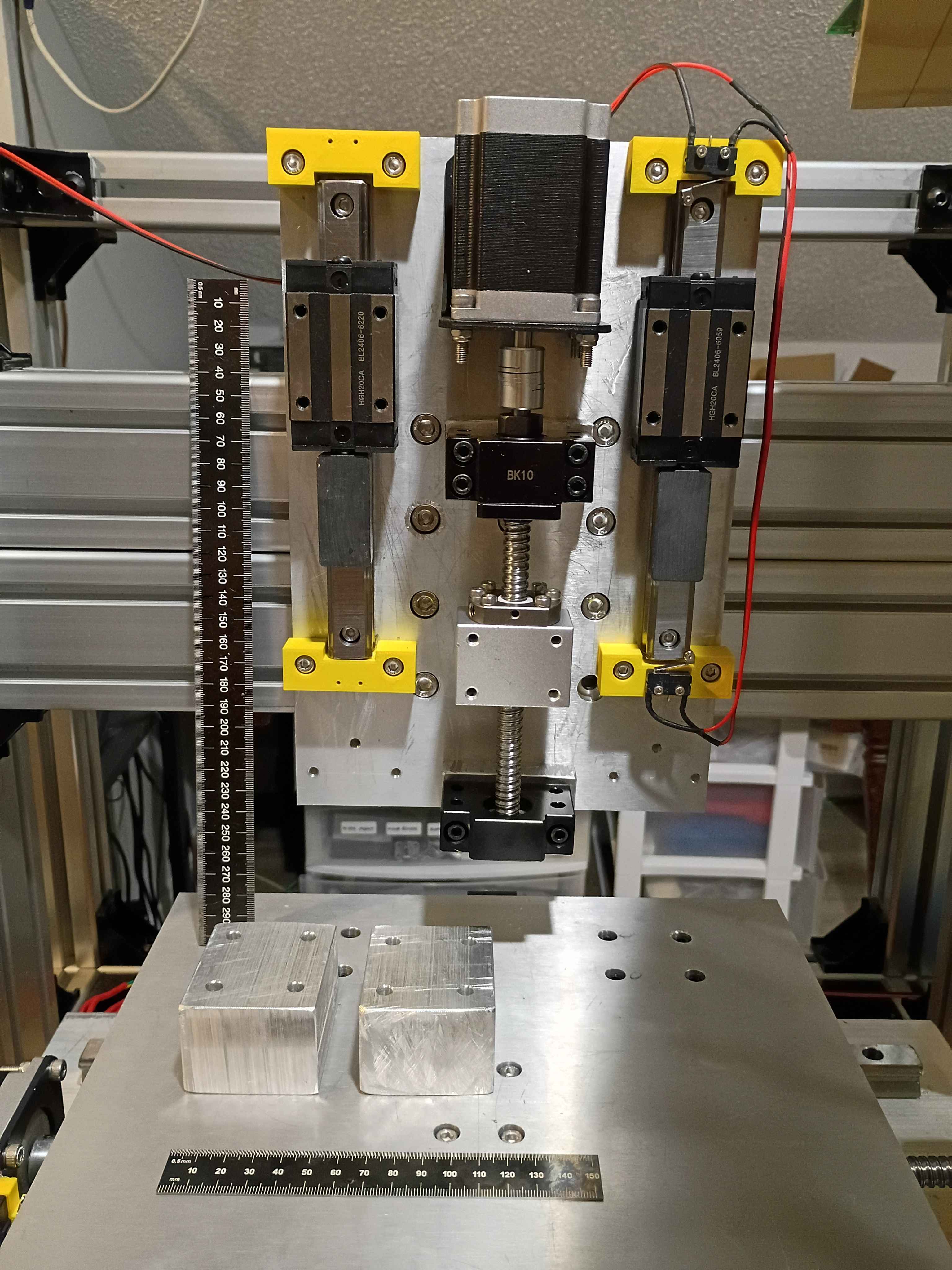
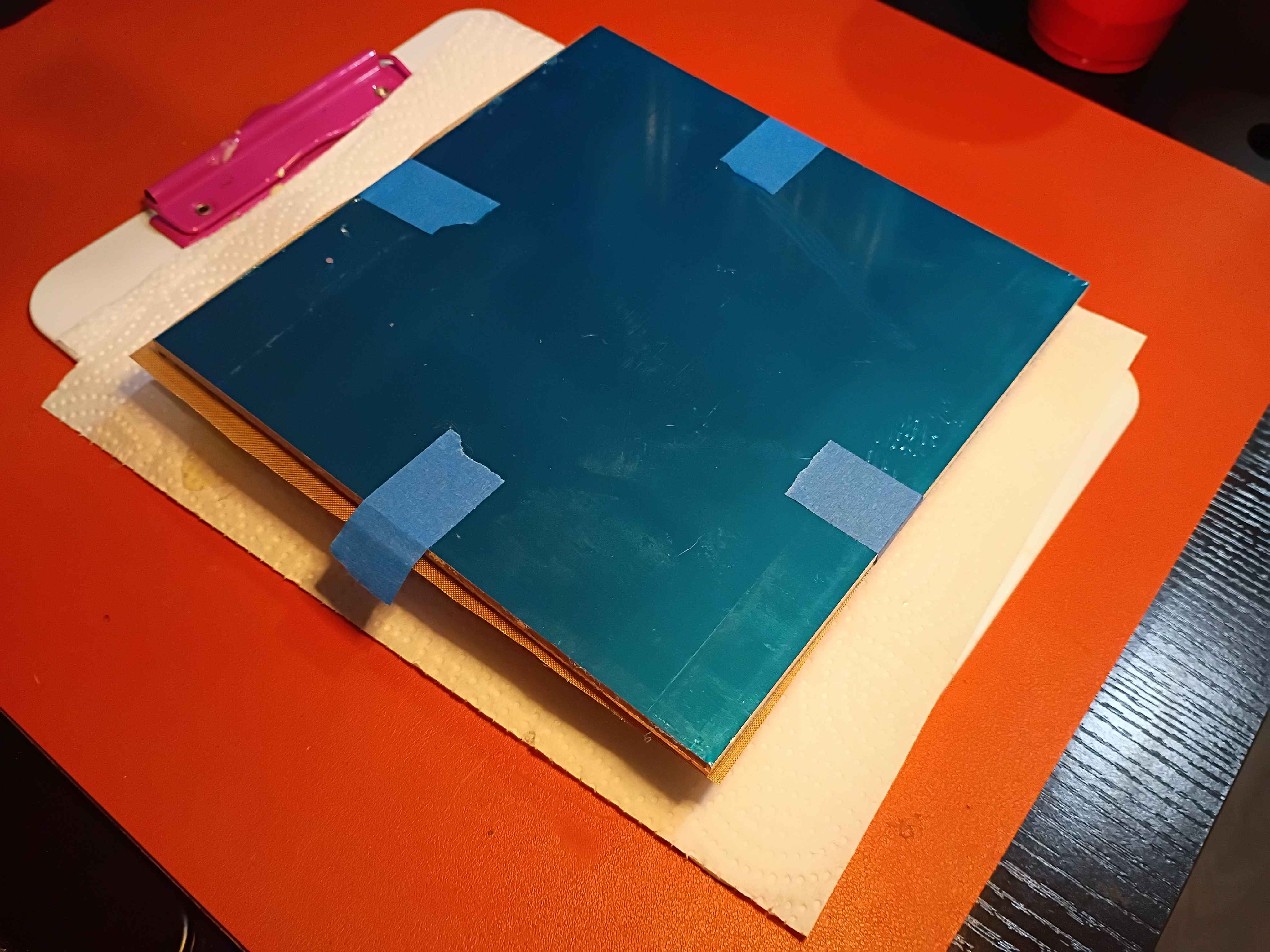
Redrilled and retapped holes for the stepper motor mount and reinstalled all the components. Used plastic to tape off the linear rails during the rework to prevent having to completely disassemble everything, while still keeping chips and dust out of the linear rail carriages. Learned that you can use a long Allen wrench to press deep-set T-slot nuts into the proper orientation (and position) while attempting to screw into them, helping avoid them getting stripped by accident. Also learned that you can use your finger in the round end of a wrench to get the right depth when trying to screw a nut onto the end of a bolt. 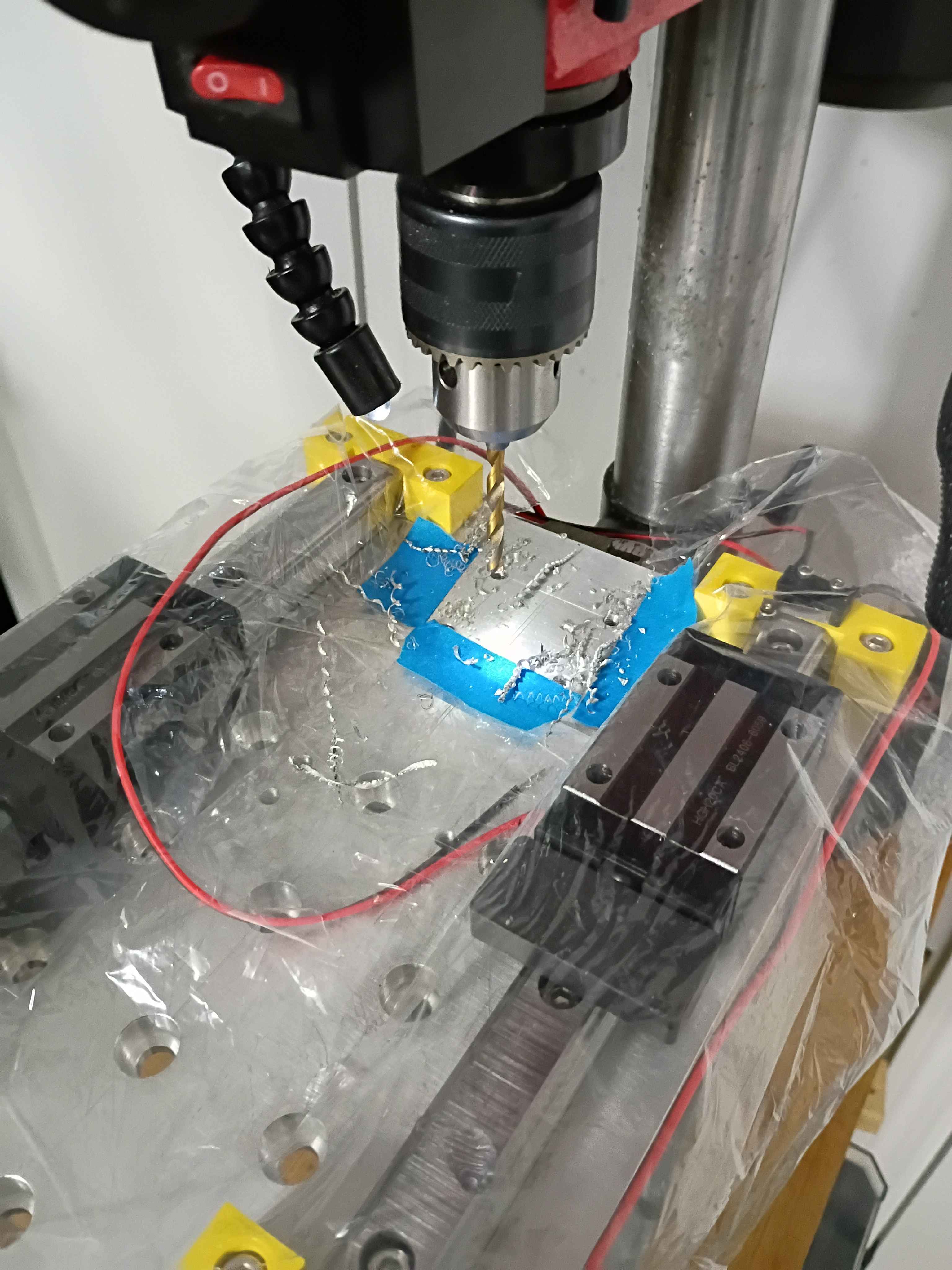
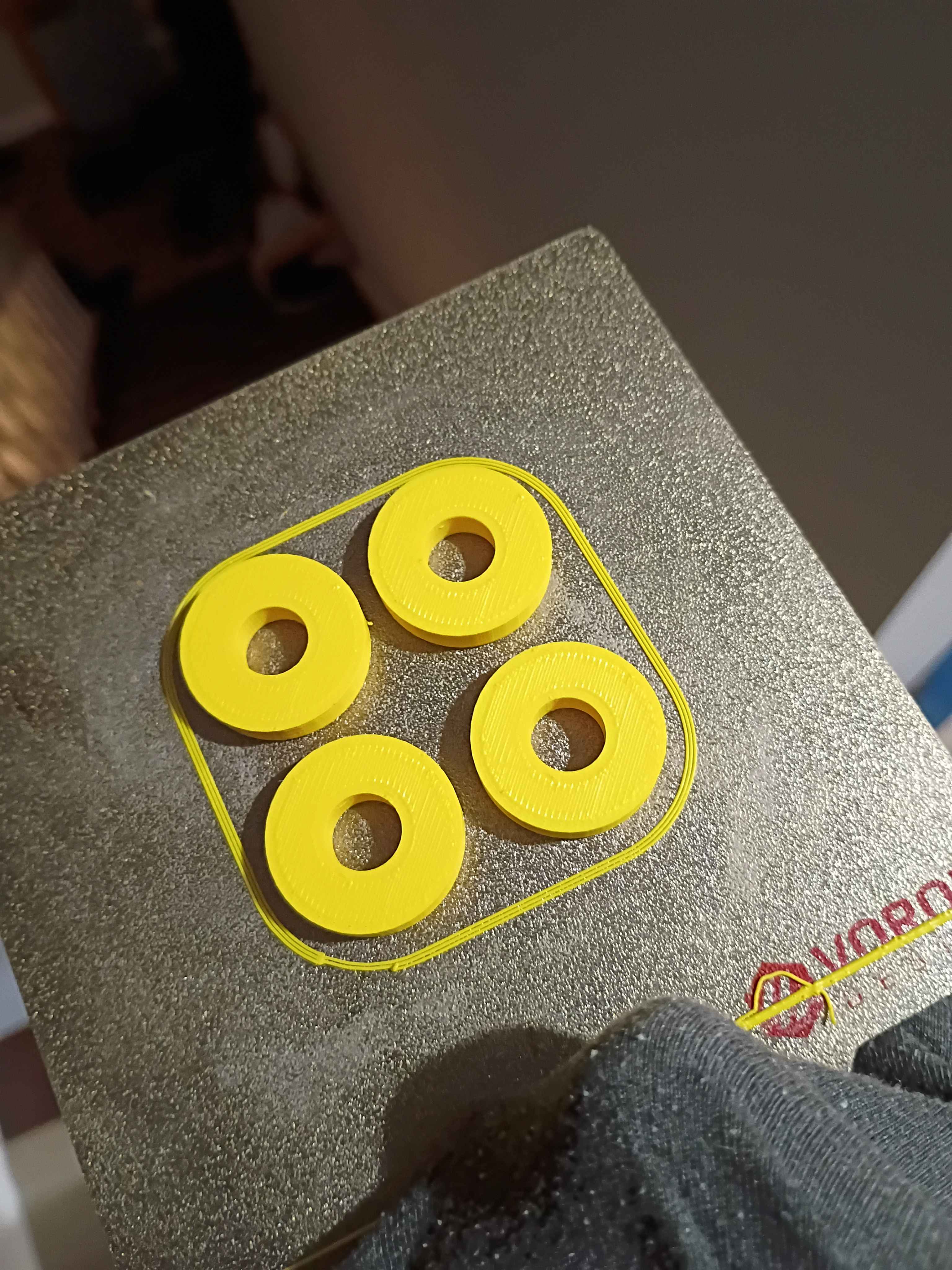
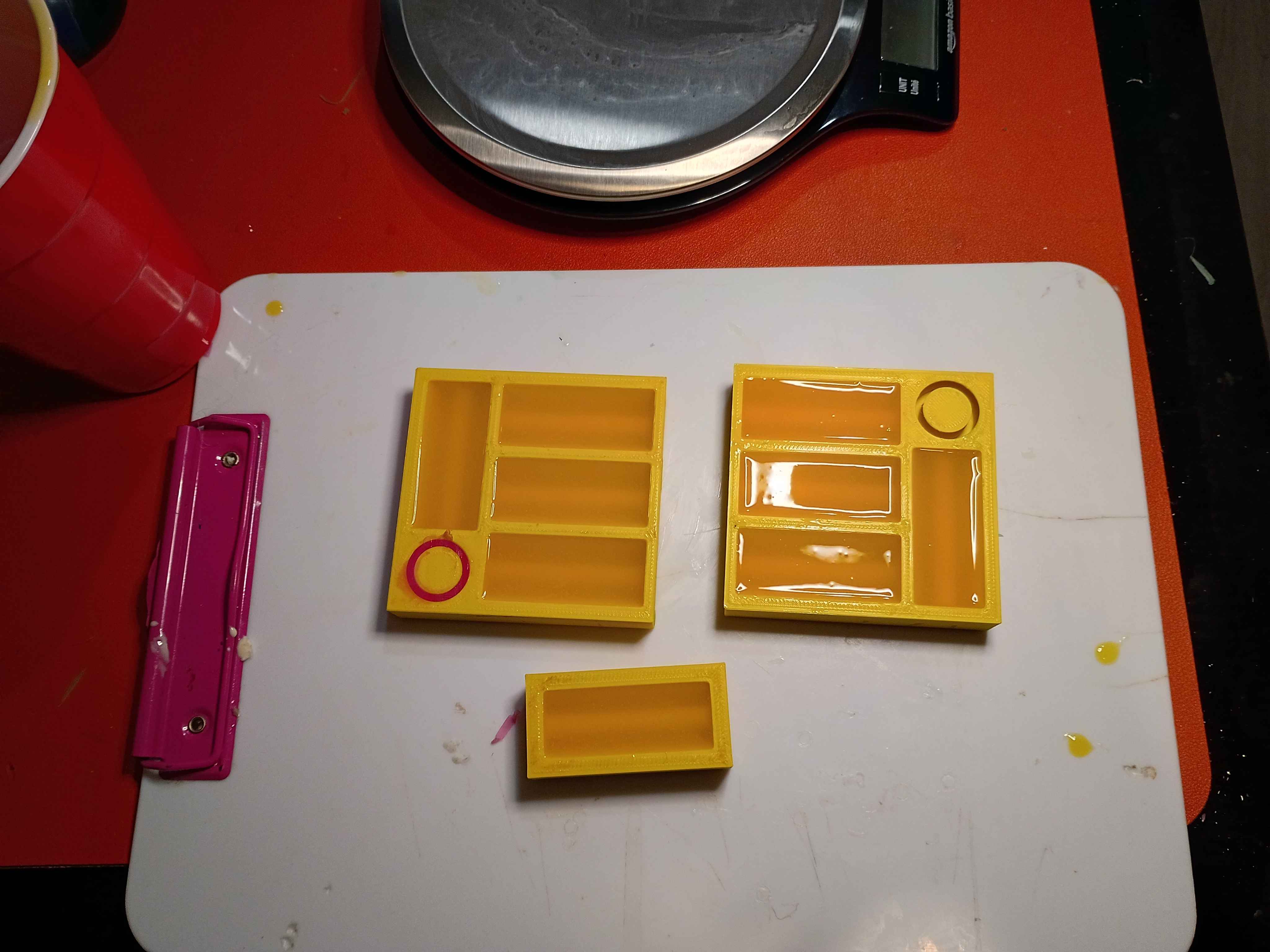
Poured a bunch more 01001-001A in green and yellow and put some double-sided adhesive strips on the back. I'm going to make >30 total in a wide variety of colors for testing with the children. 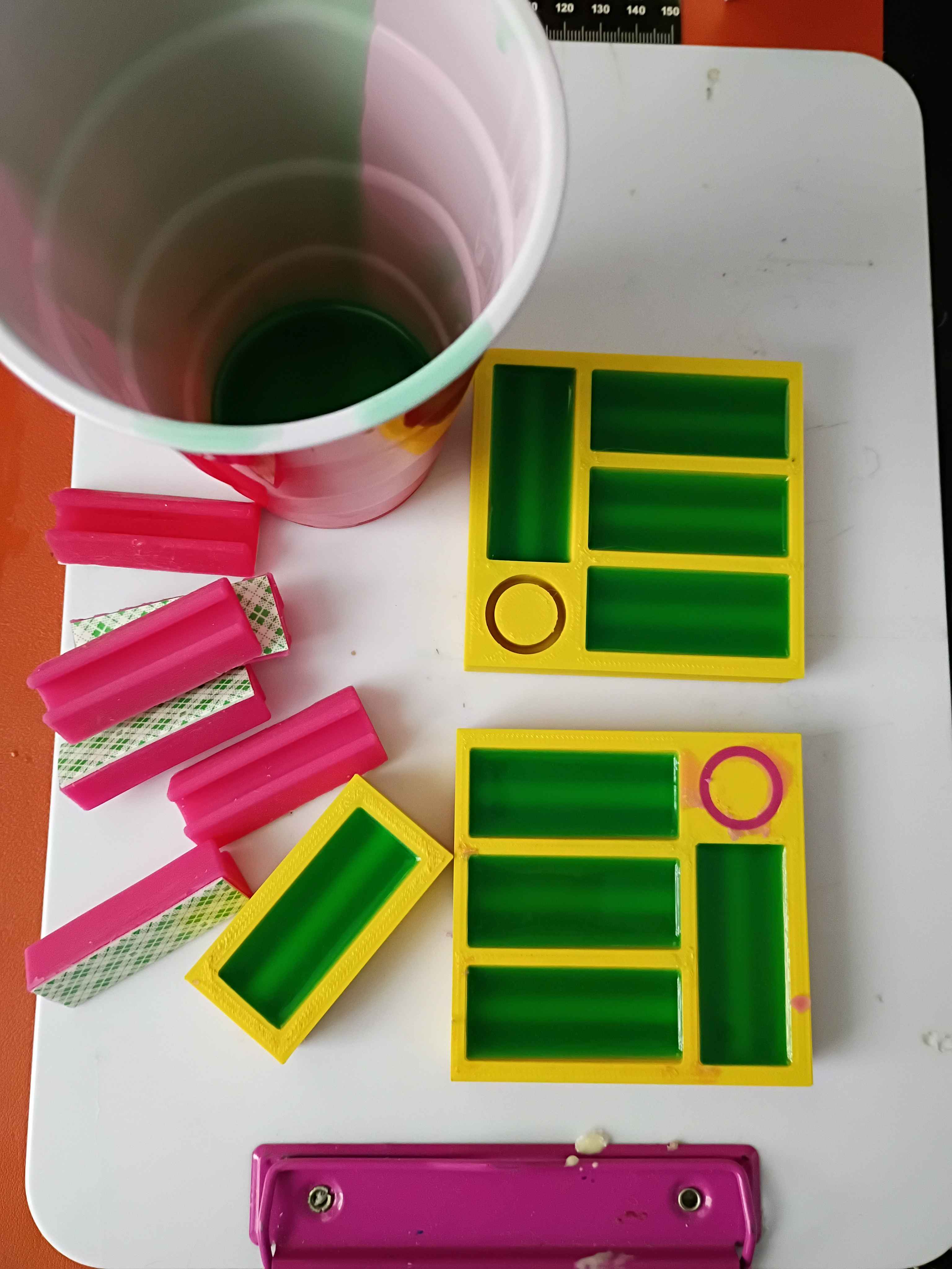
Printed 01001-001AT2 and poured 5x pink pencil houses and one ring-looking thing, though that one will probably be a pain to pull out. Need a way to pour the silicone more slowly to avoid overfilling the molds. 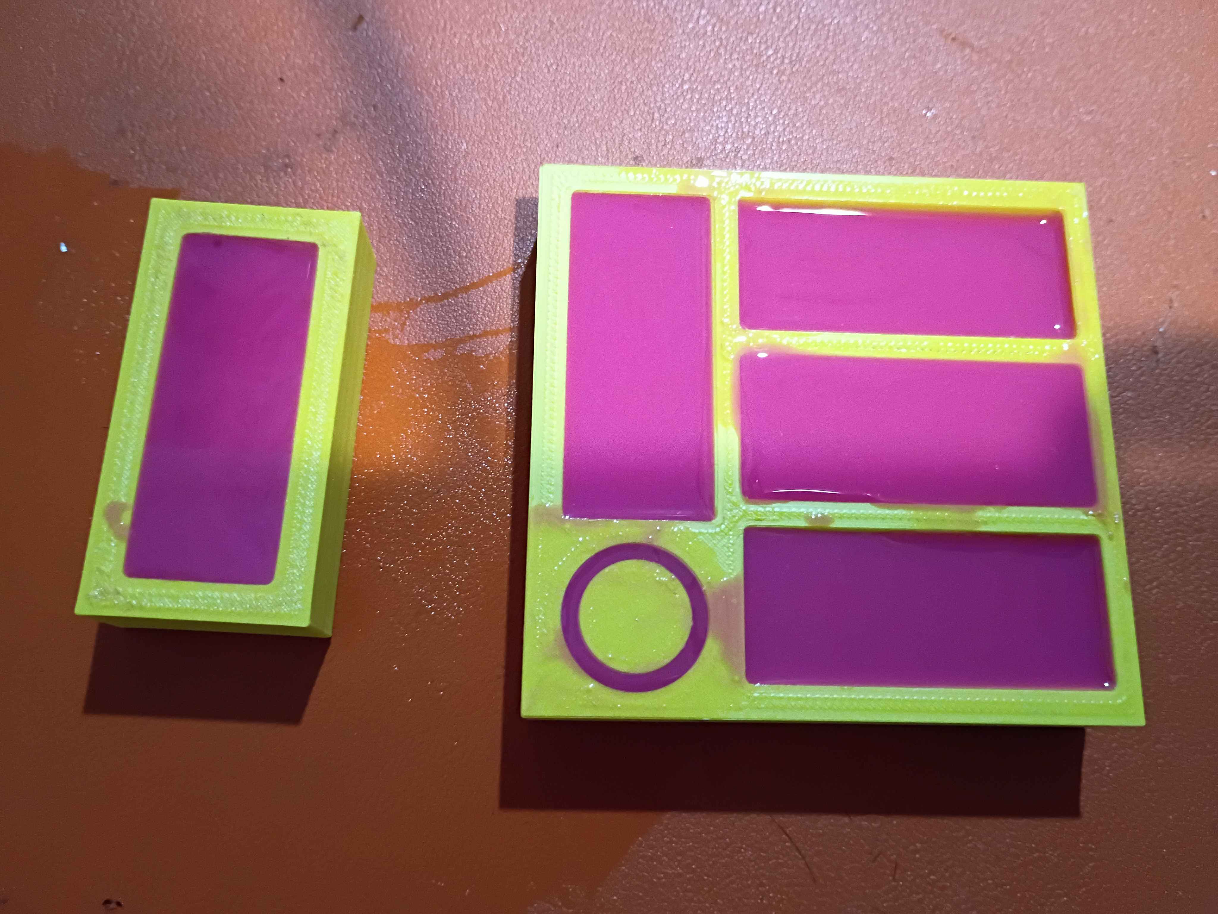
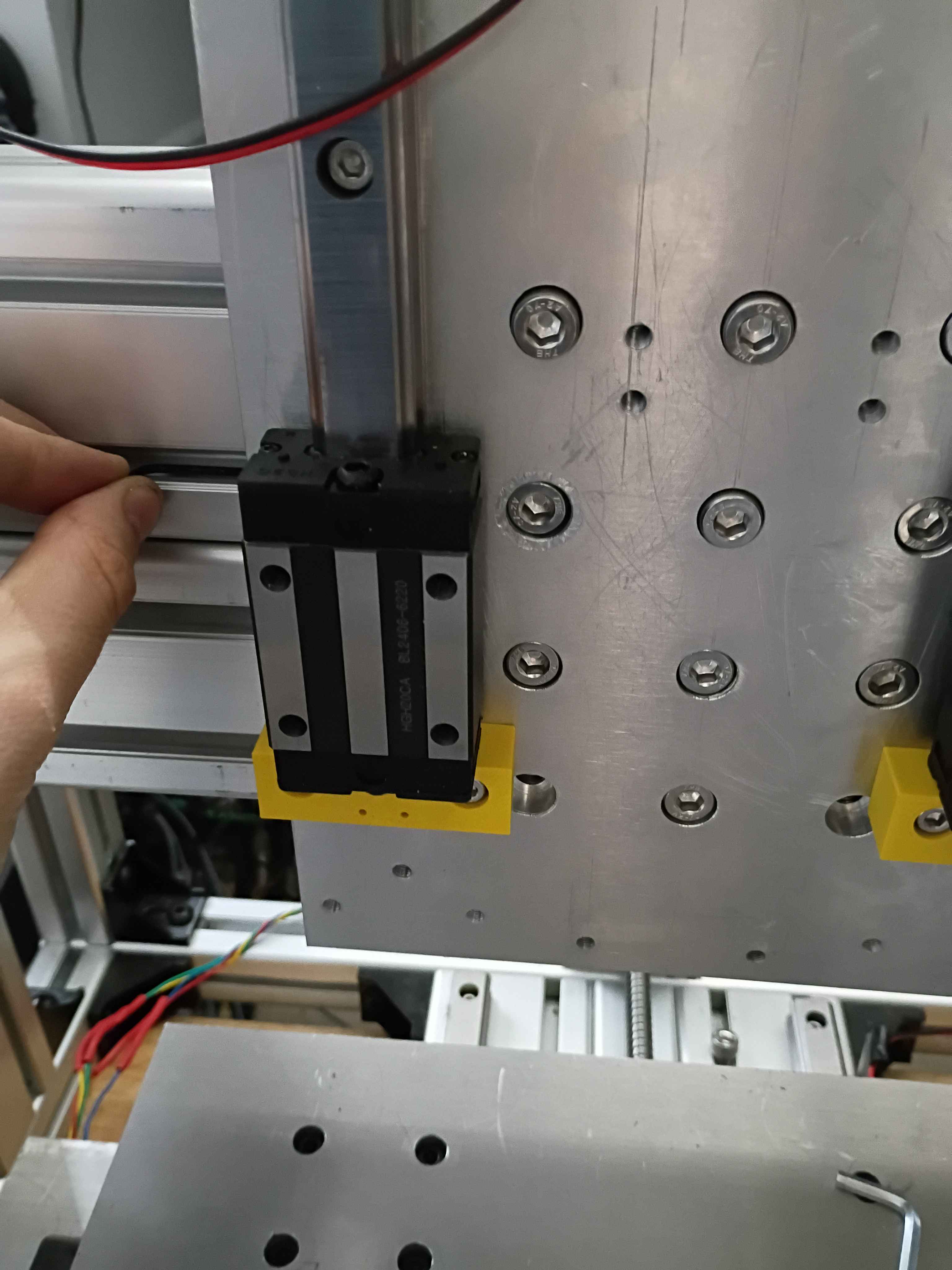
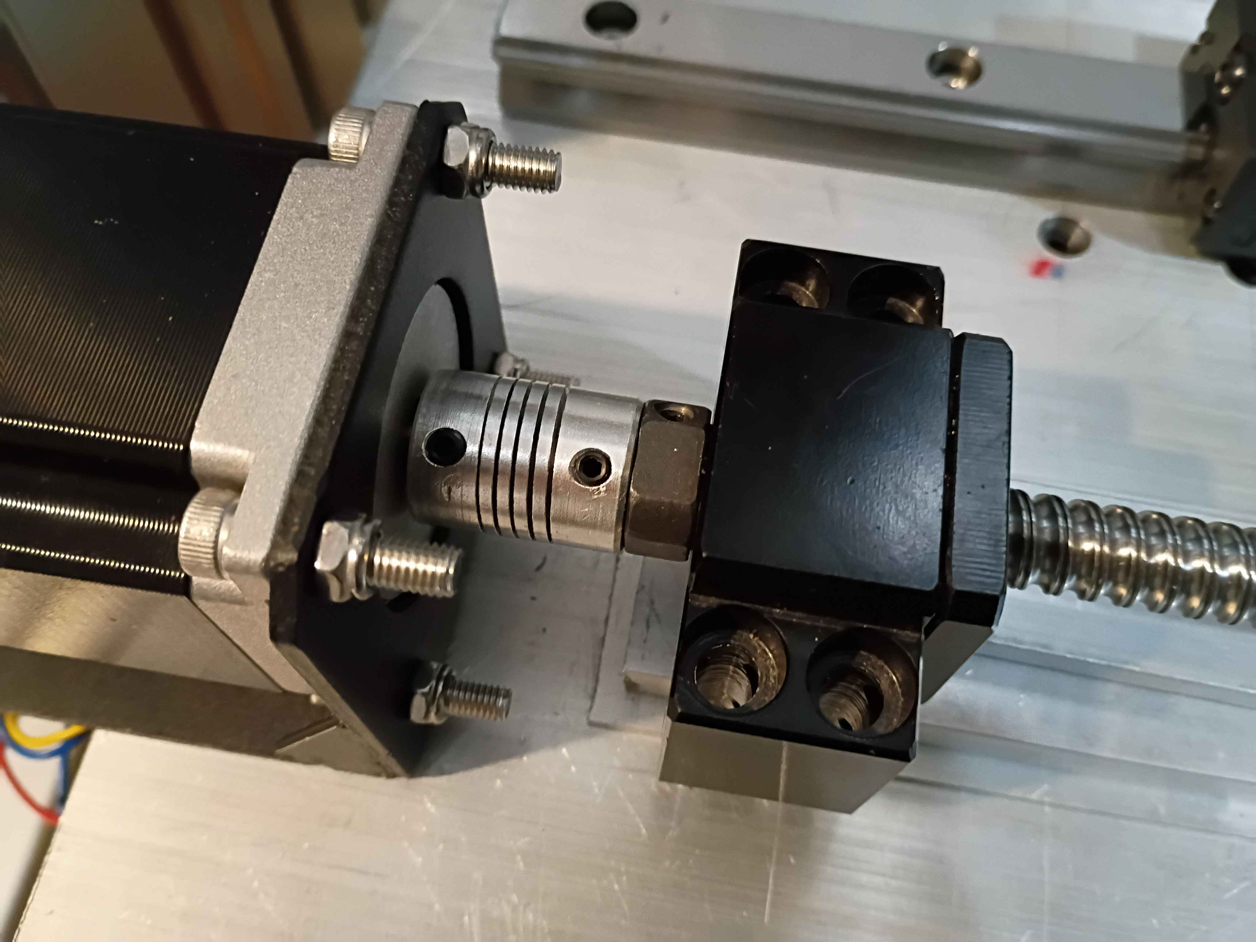
Did a lot for the z-axis linear motion system. I will need to disassemble and redrill 4 holes for the stepper motor mount because they are too close to the ballscrew. And I think I might possibly drill an access hole to remove an M8 t-slot nut embedded in the Aluminum extrusion that has faulty threads to replace it without having to disassemble the entire frame assembly. 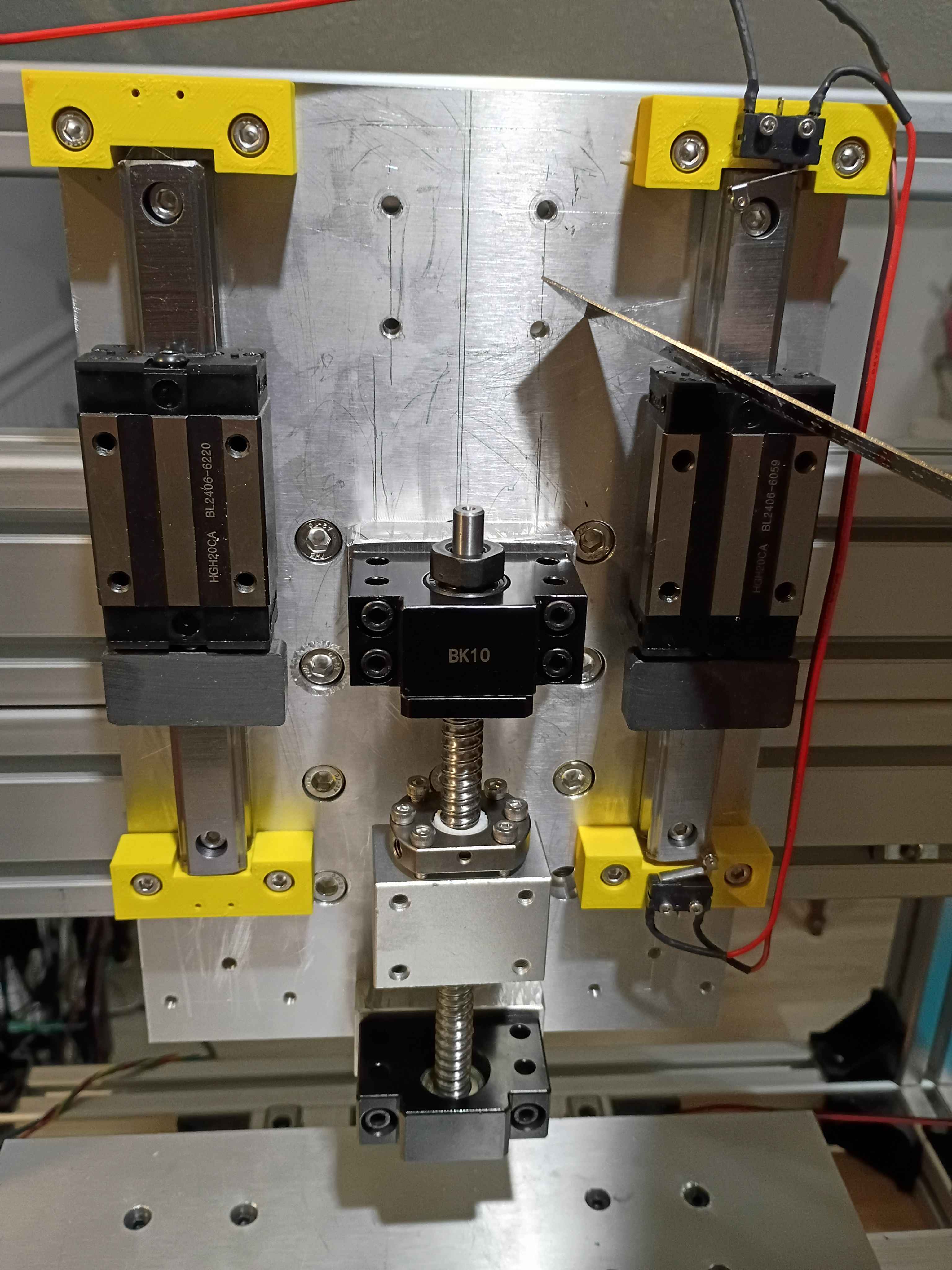
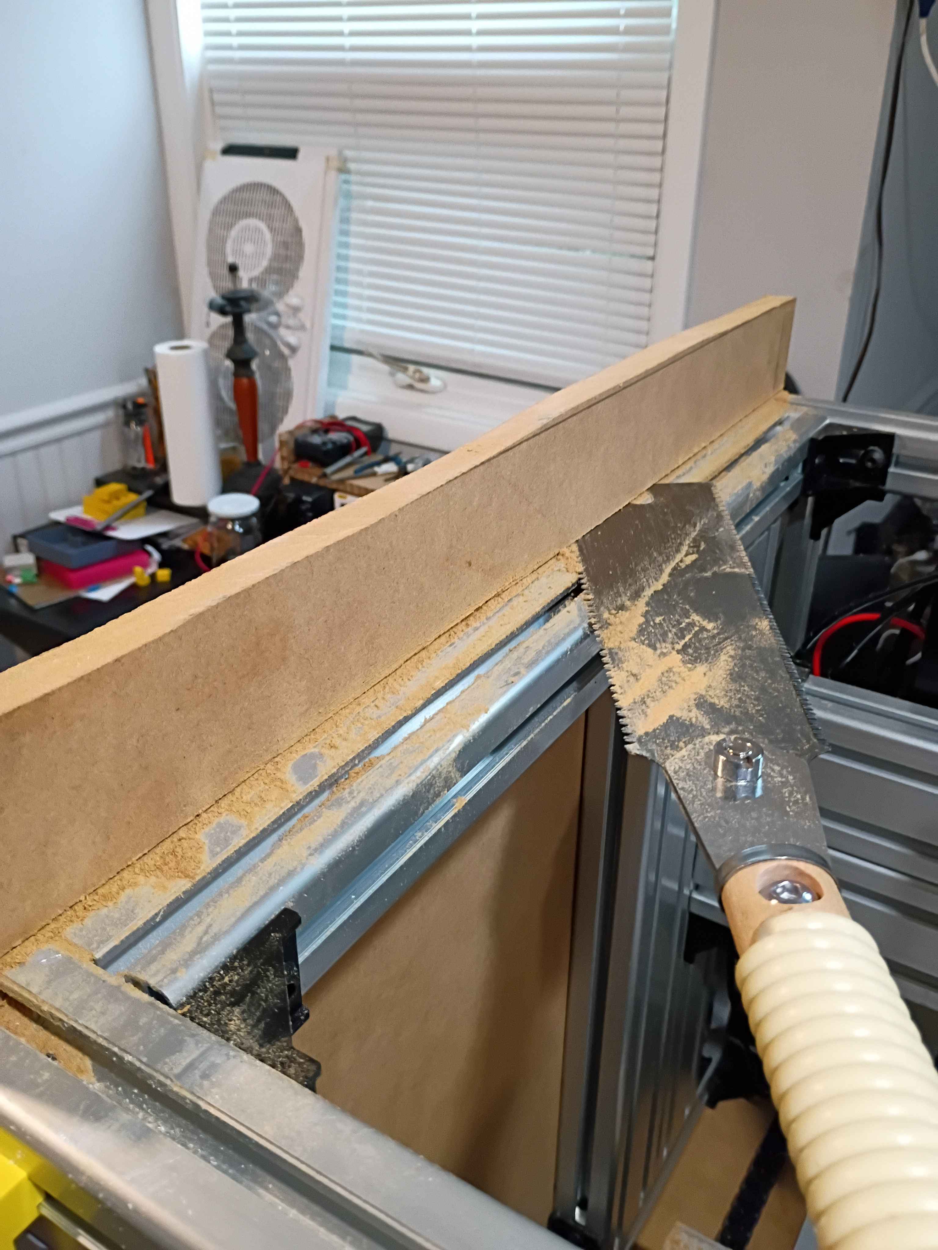
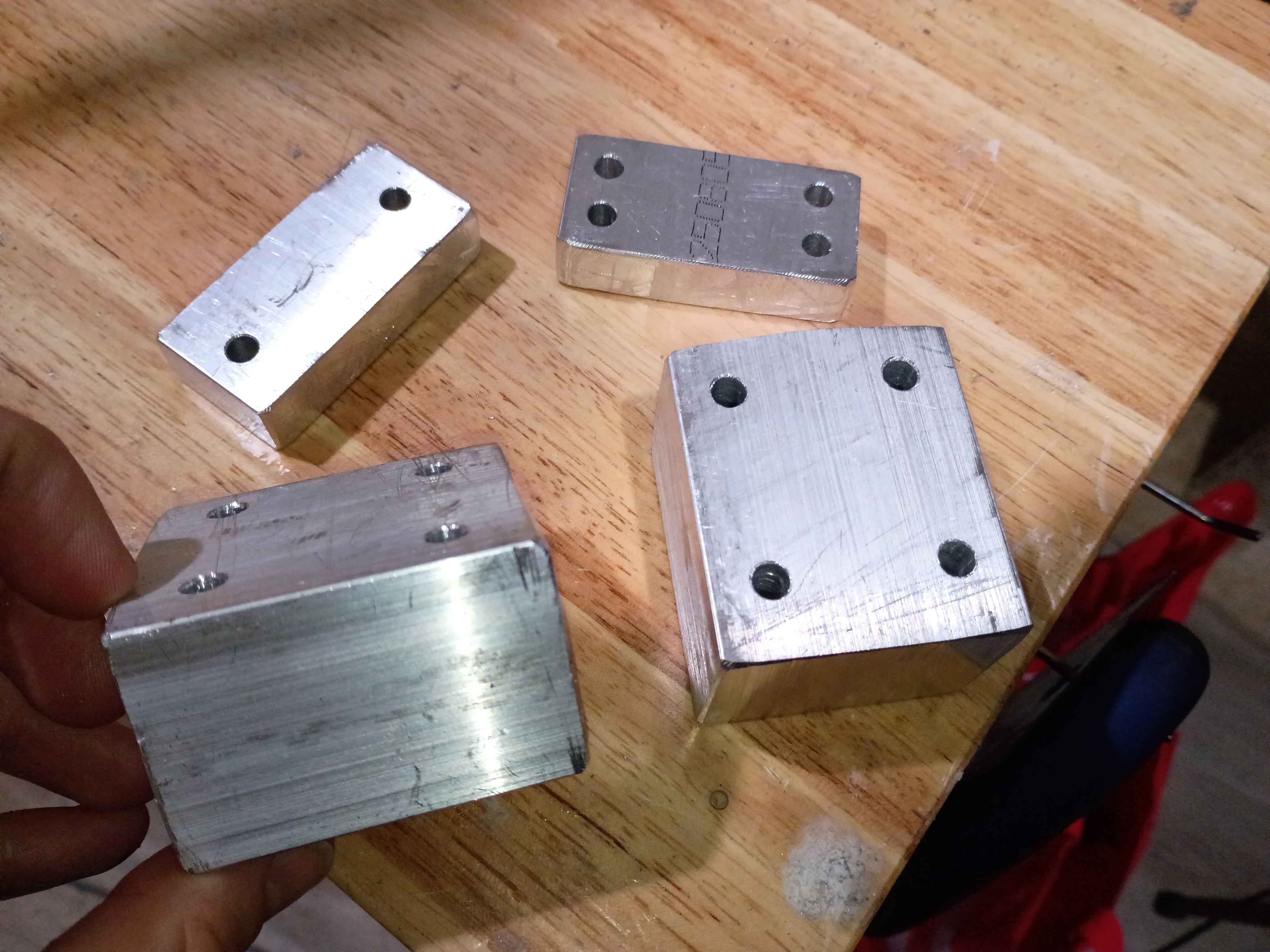
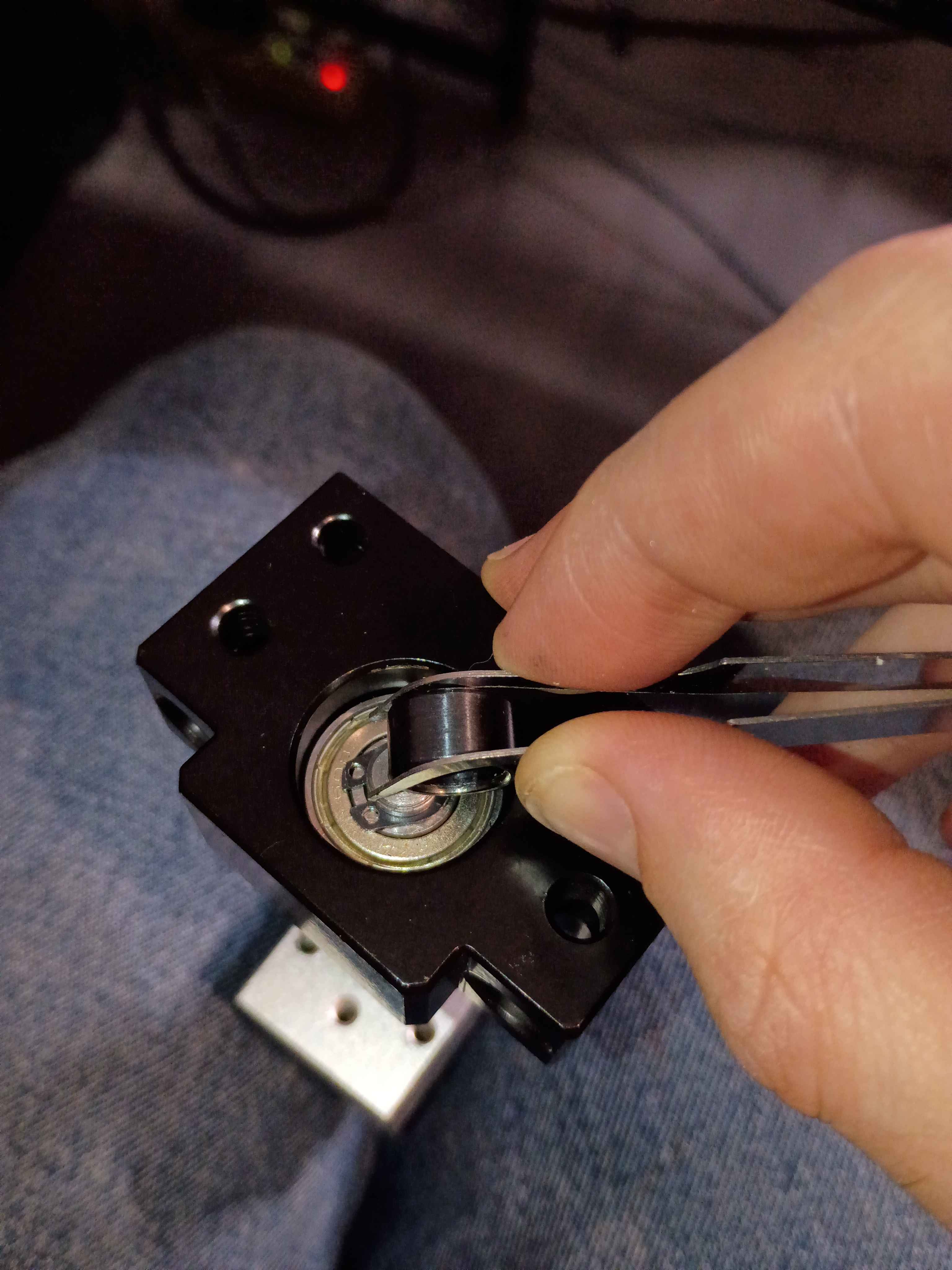
Cut, filed, and drilled spacer blocks for the z-axis motion system clearance. Discovered that for making straight hacksaw cuts through thick material, you can cut a trace around the entire perimeter first, and that will help guide the saw through straight. Also discovered that you can install the circlips using those IC tweezers to grab the holes and a small (ideally round) object that you can slide in between to spread the circlip open; it worked surprisingly well. Also observed that the shop-vac made super quick work of the aluminum chips and oil-file dust - way better than wiping or sweeping. 
The second attempt (01001-001A came out perfect, with just the right amount of grip, so I design another tool (01001-001T2 that can produce 4 at a time. It also has a deeper recess to prevent any silicone from overflowing the top. This model is printing with very fine layers (0.10 mm) overnight. 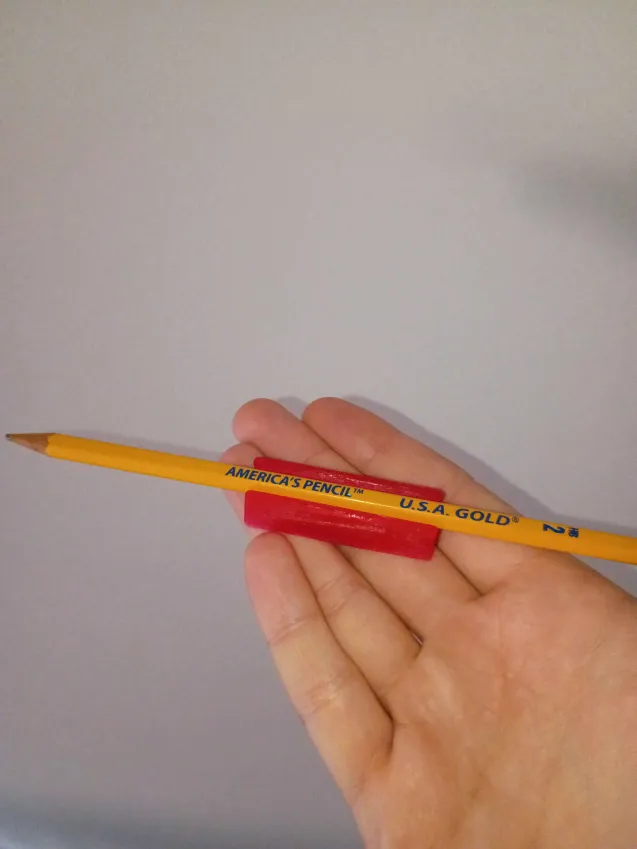
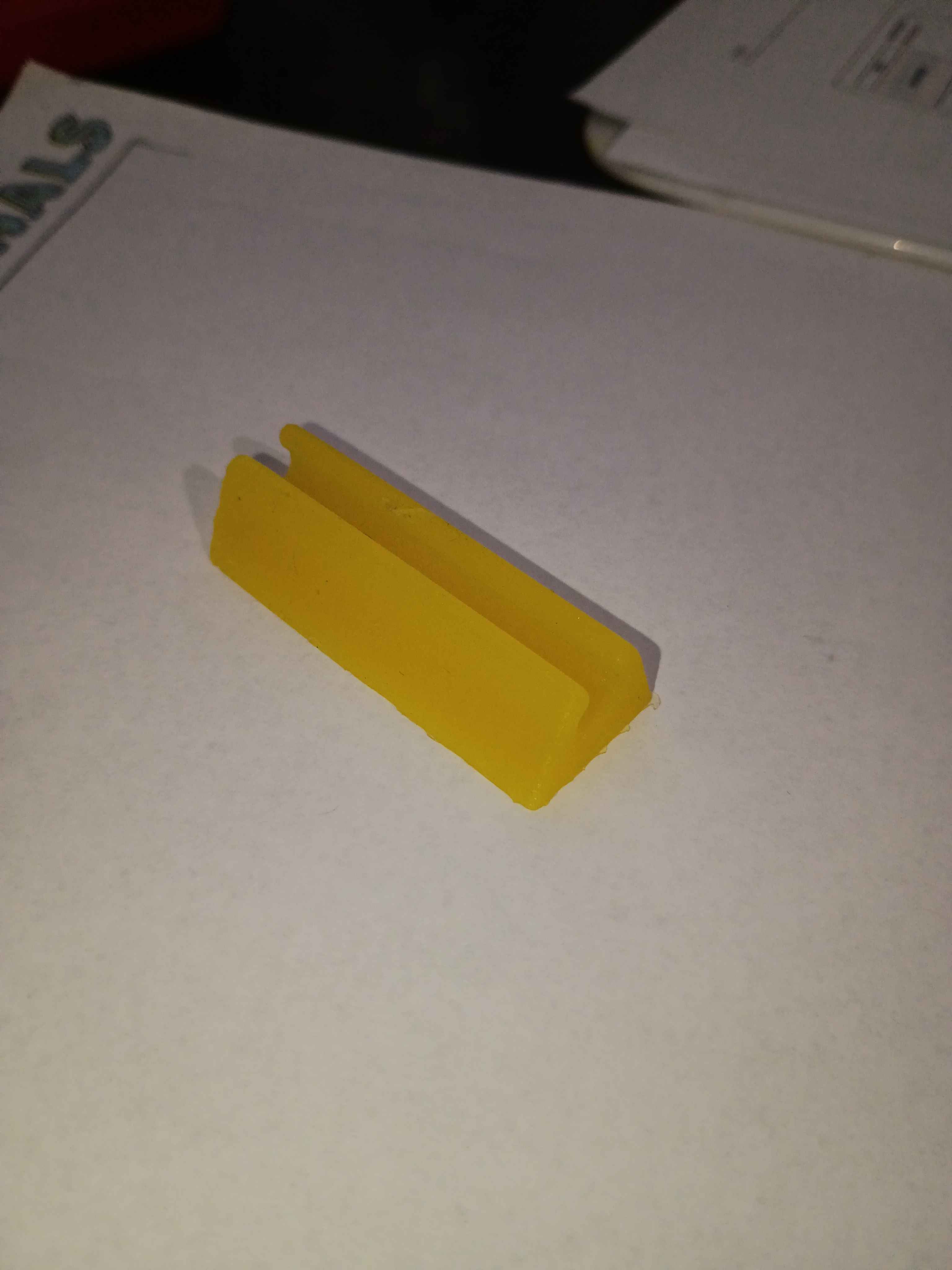
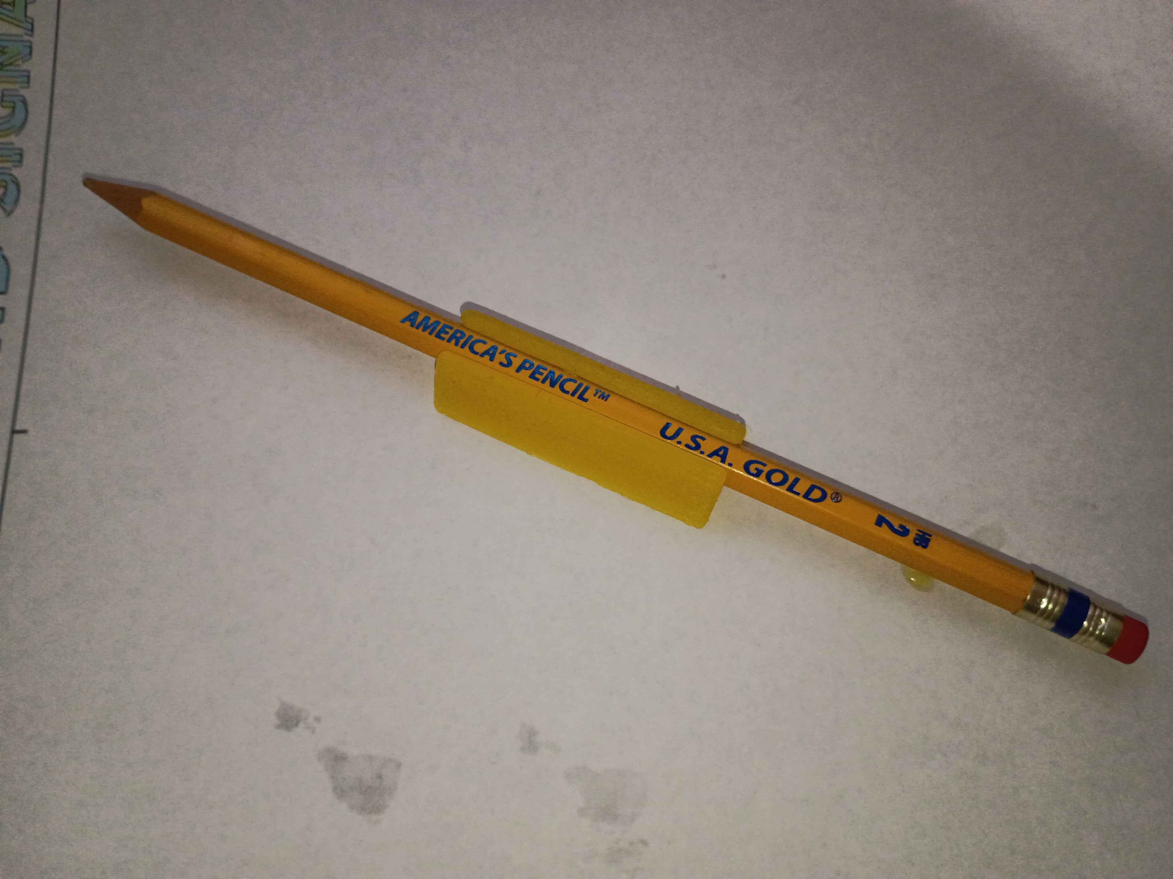
Demolded the cured 01001-001 pencil holder, and it came out well. The surface needed a few more hours to dry outside of the mold because it was sticky. It ended up holding the pencil too tightly, so I redesigned and reprinted a 01001-001A and poured some more silicone. It's cool that I can iterate so quickly on these molded designs. 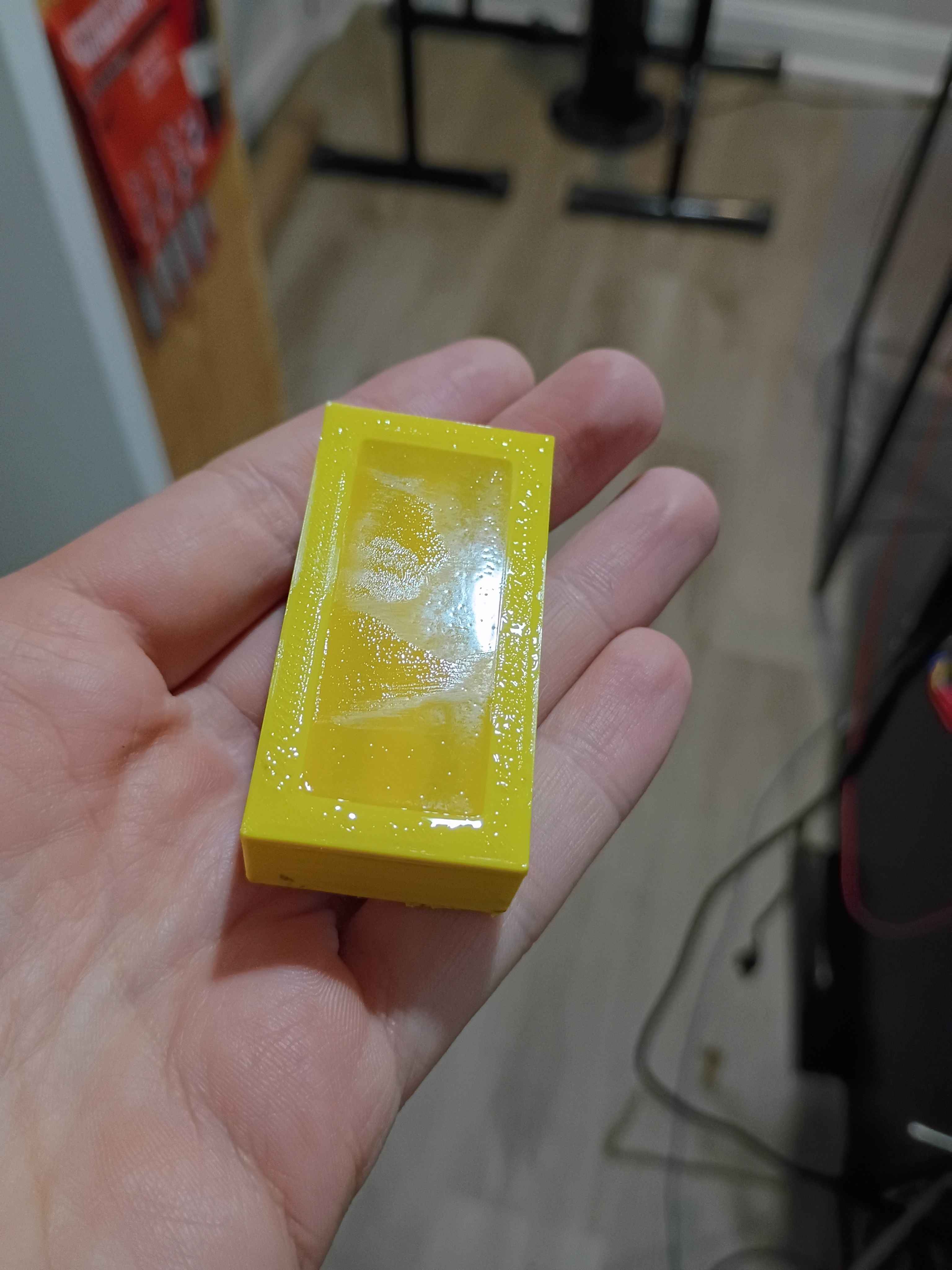
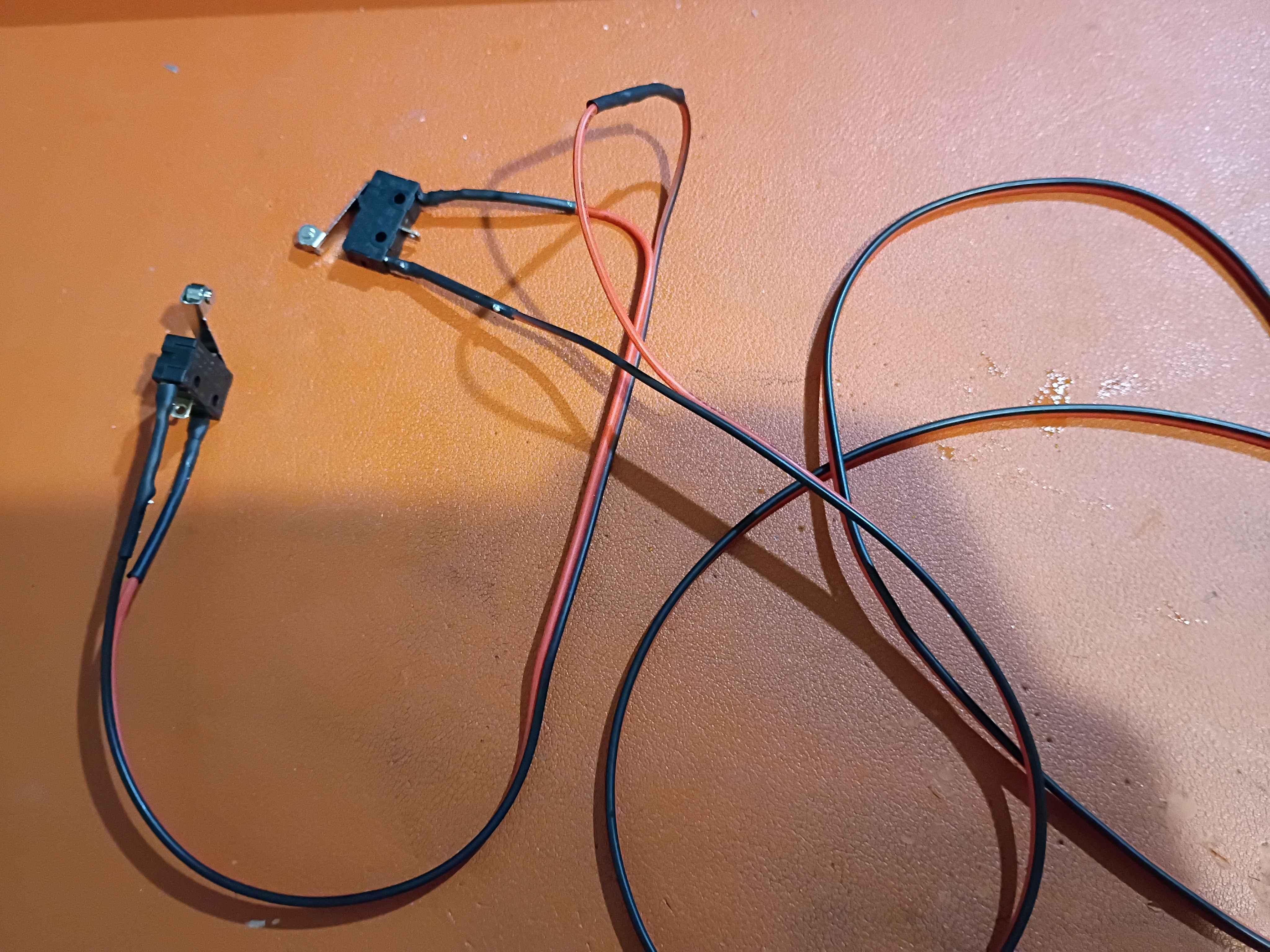
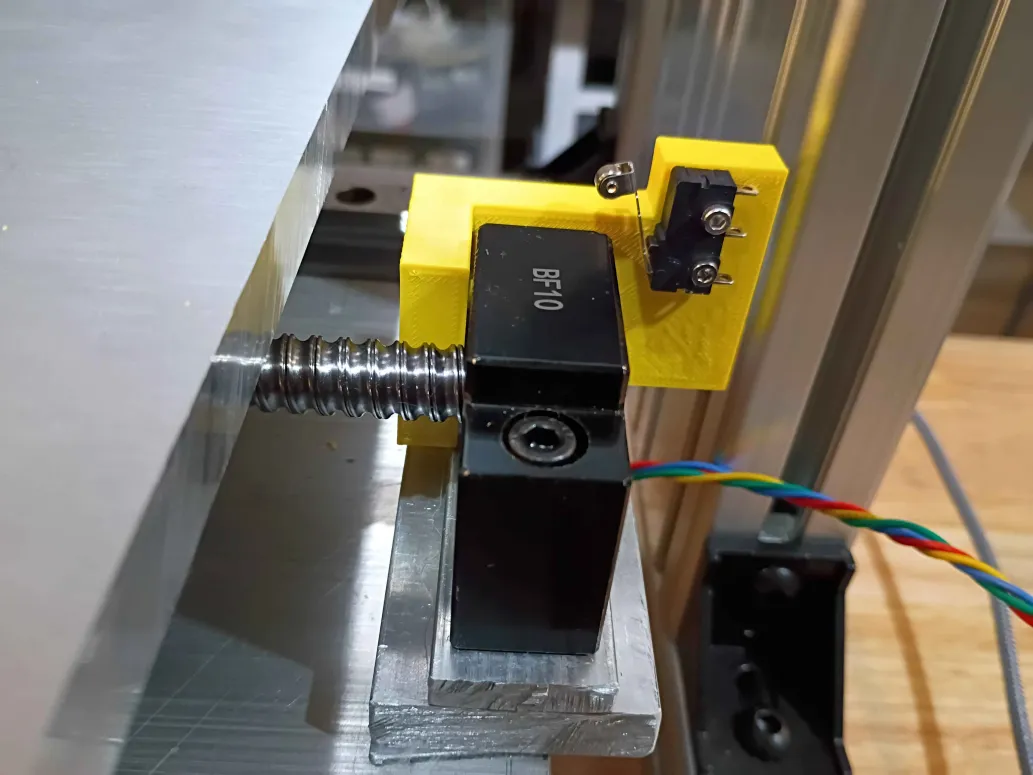
Installed 2x corrected 00001-001B along with the limit switches. Should have probably cut a longer connecting wire between them, but this will do for now. 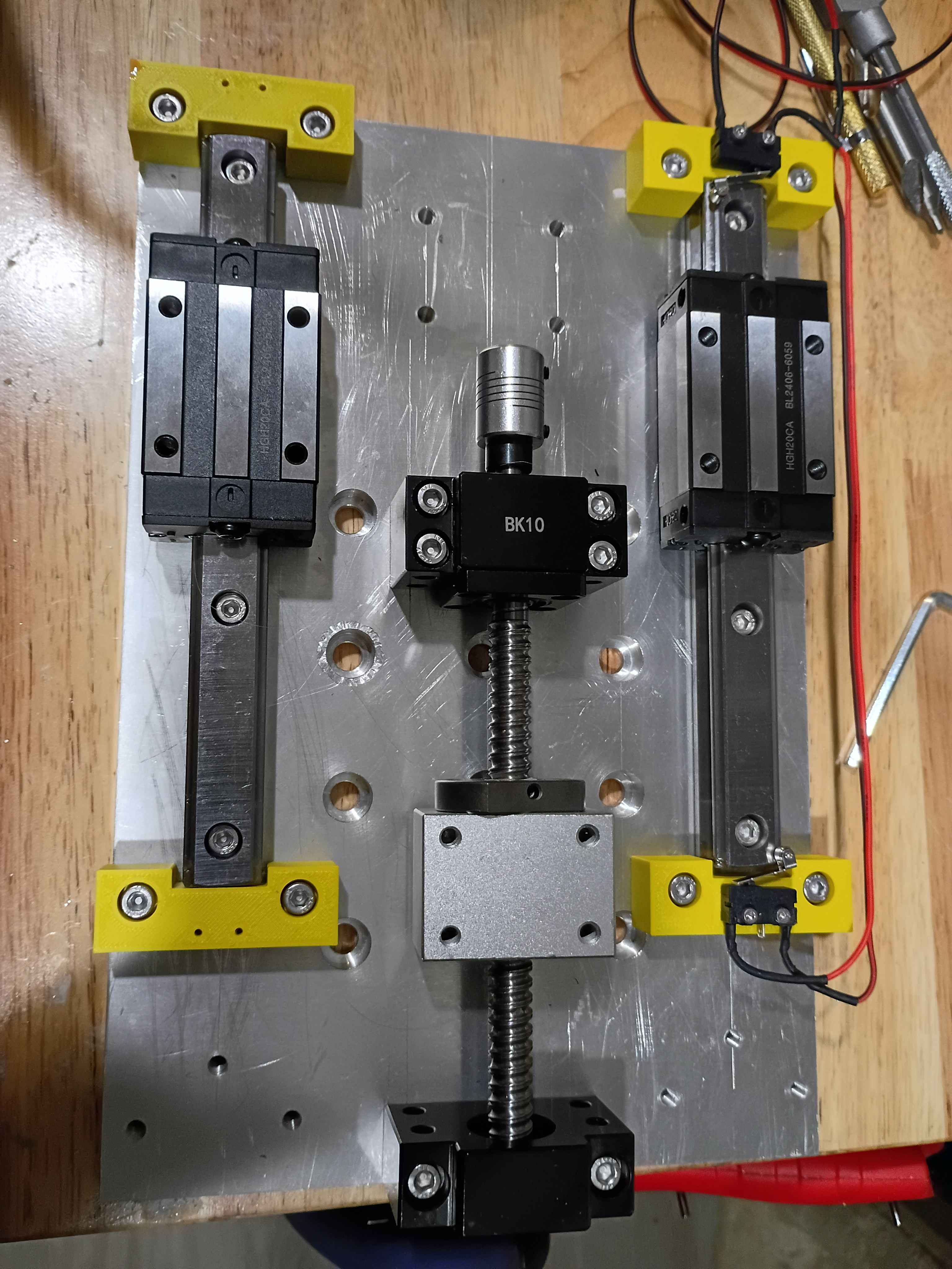
Put 01001-001T1 in an acetone vapor bath, and it helped reduce the amount and severity of layer lines. The part was quite sticky after I pulled it out after being in there for 20 minutes. I pour some Shore 40A silicone into the mold, and I will check the results tomorrow. 
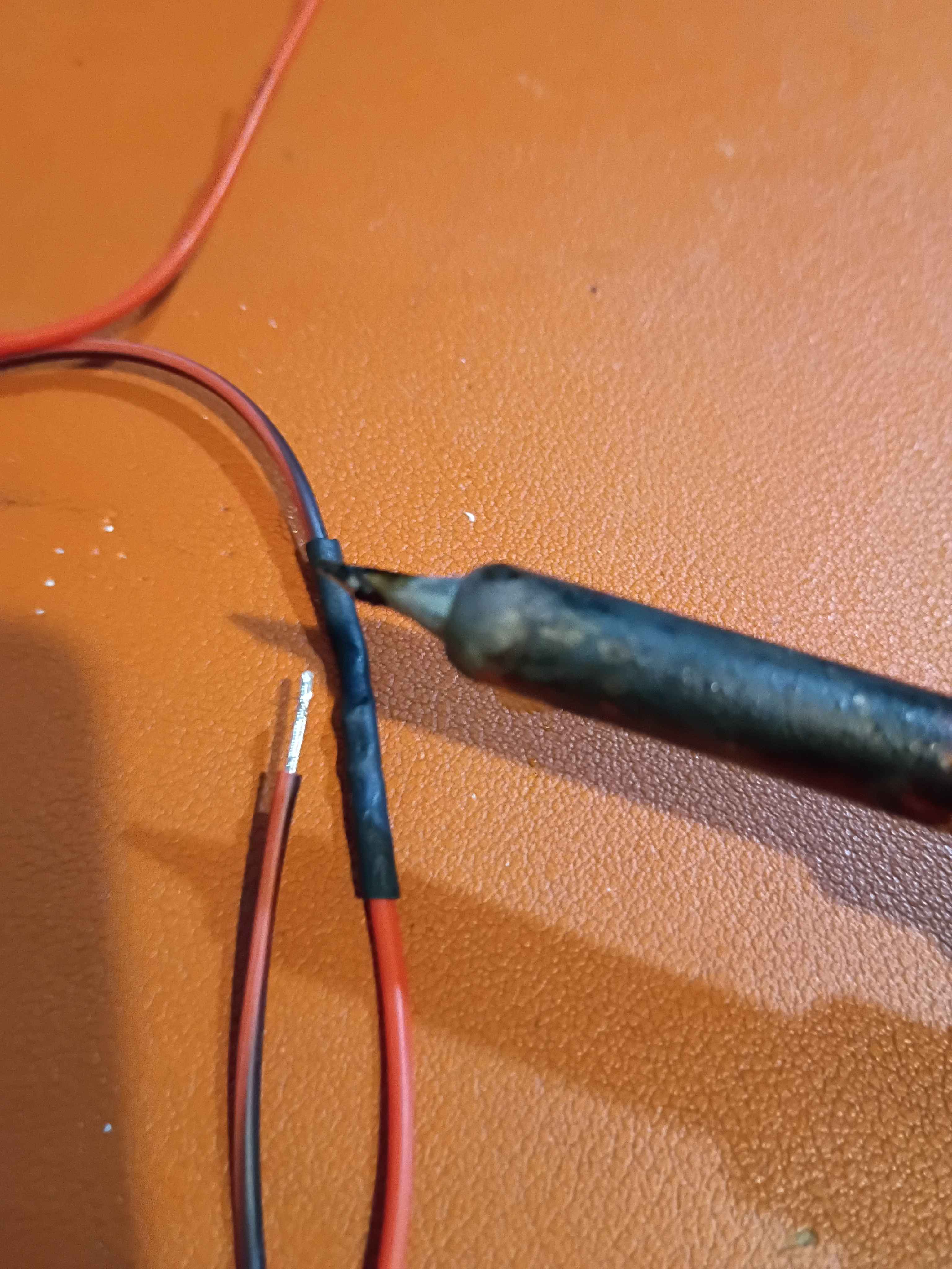
Printed 4x endstop blocks and attached those linear motion components. Realized I need to slightly adjust the limit switch mount holes, so the 00001-011B was redesigned and is being reprinted overnight. Soldered up the series NC limit switches. Realized that with the new narrower heat shrink tubing, the side of the soldering iron is sufficient to shrink the tubing without burning anything, whereas my normal approach of the heat gun for the thicker tubing sometimes causes nearby plastic, especially 3D-printed plastics, to melt. 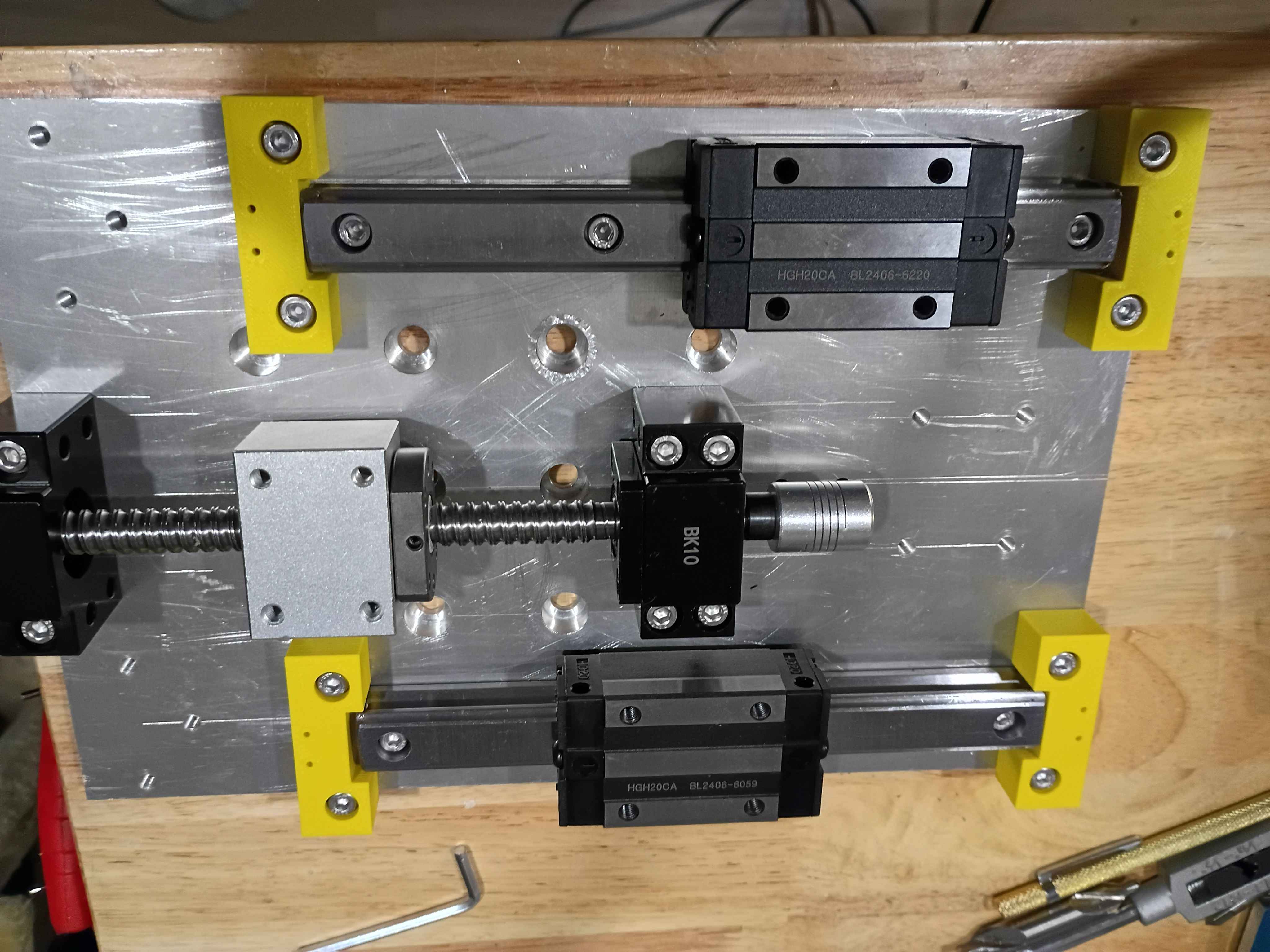
Revised the 00001-011A endstop blocks to handle better tolerance variation in the linear rail ends, as well as having mount points for limit switches. These are being printed overnight. Also determined the required spacer thicknesses for the z-axis motion components, and purchased them on McMaster. 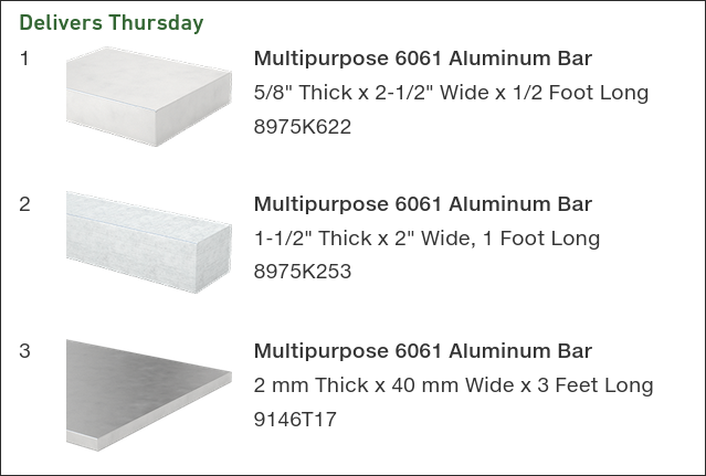
Added some capability to Mary-Bot to track the journal entries in a large JSON database instead of discrete INI files. These two methods are currently tracked in parallel, though the new version will be more extensible and lend itself to future planned updates.
Printed 01001-001T1 tool out and sourced silicone of the proper Shore hardness (40A). 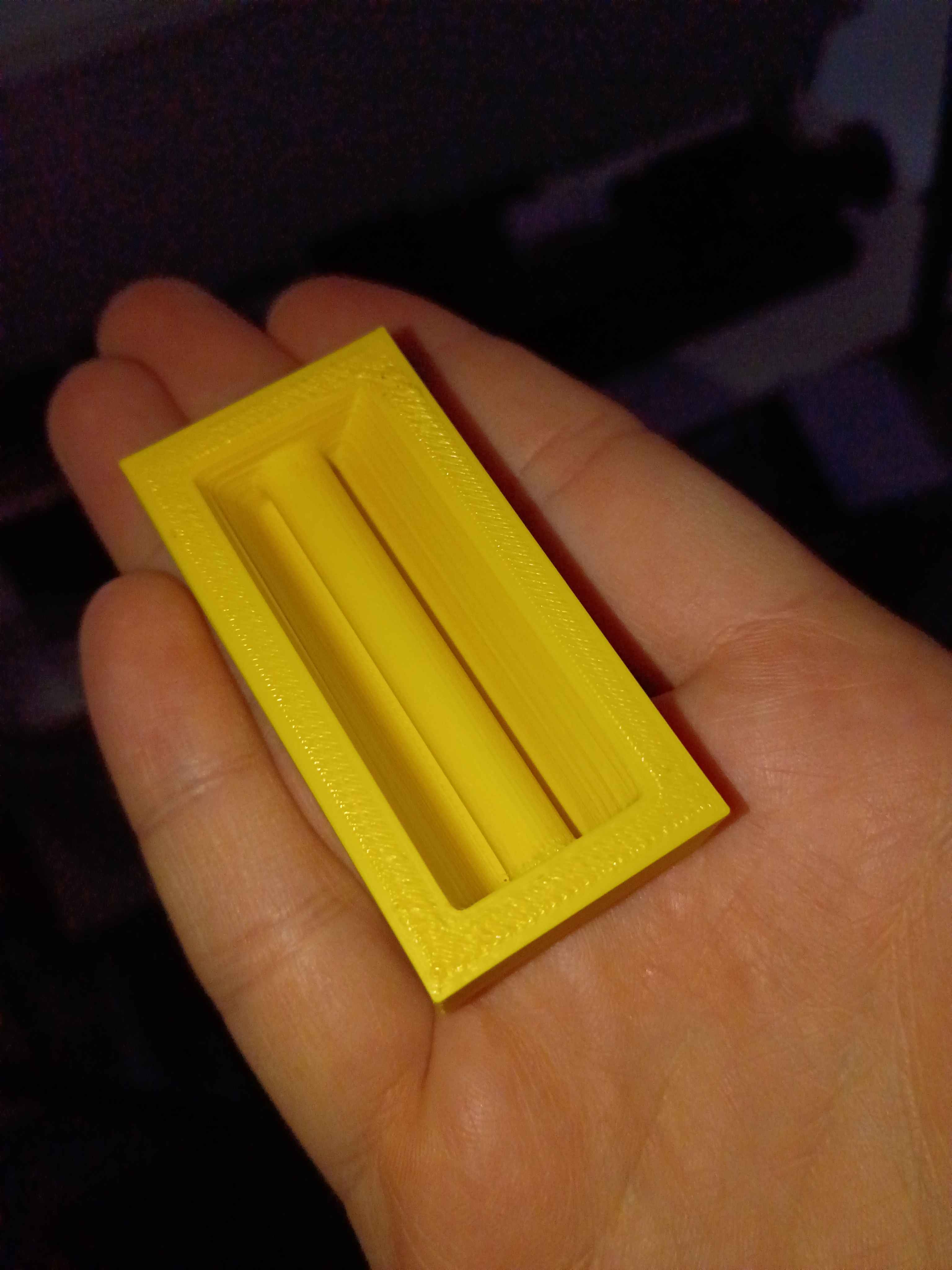
Designed and printed z-axis linear rail carriage blocks. 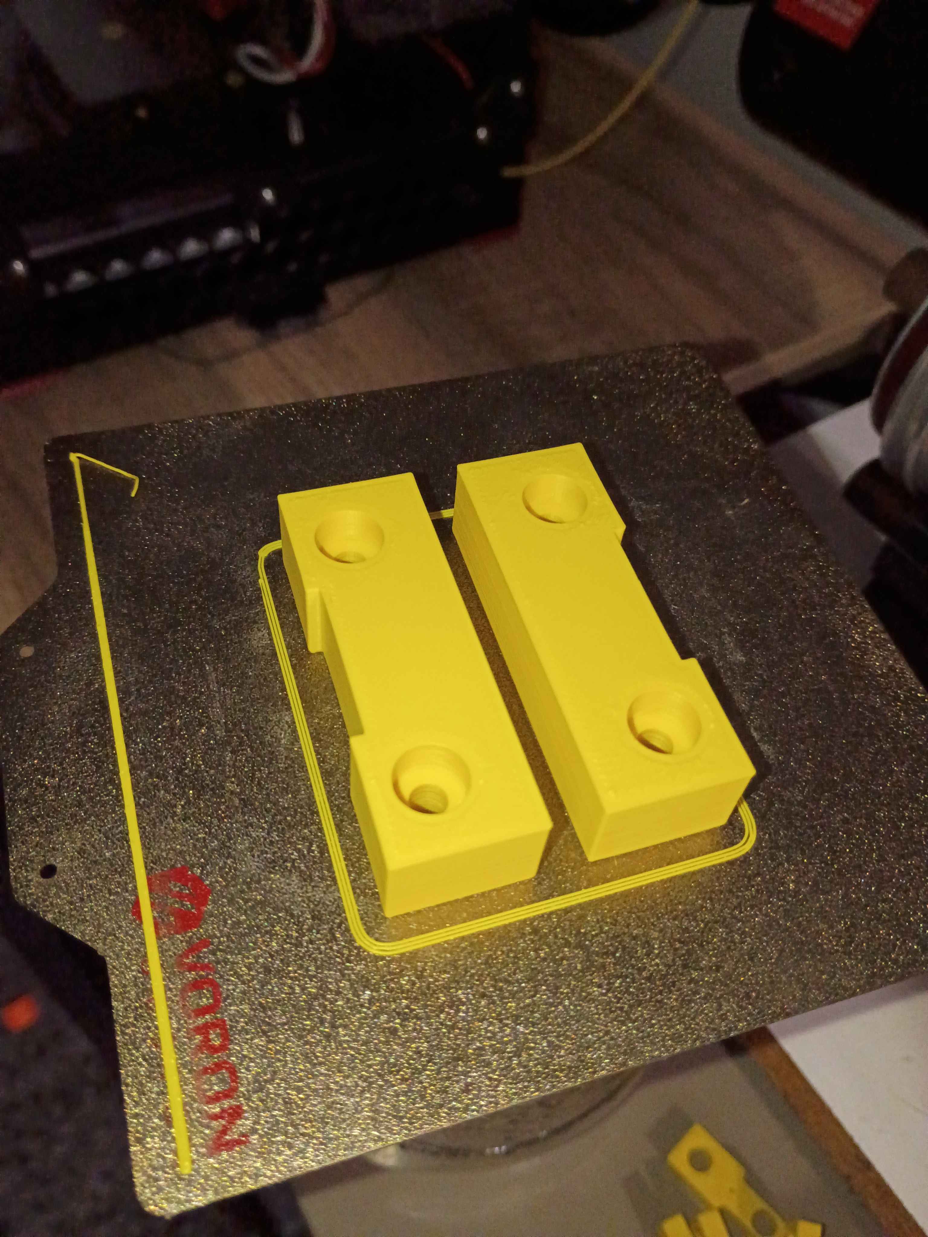
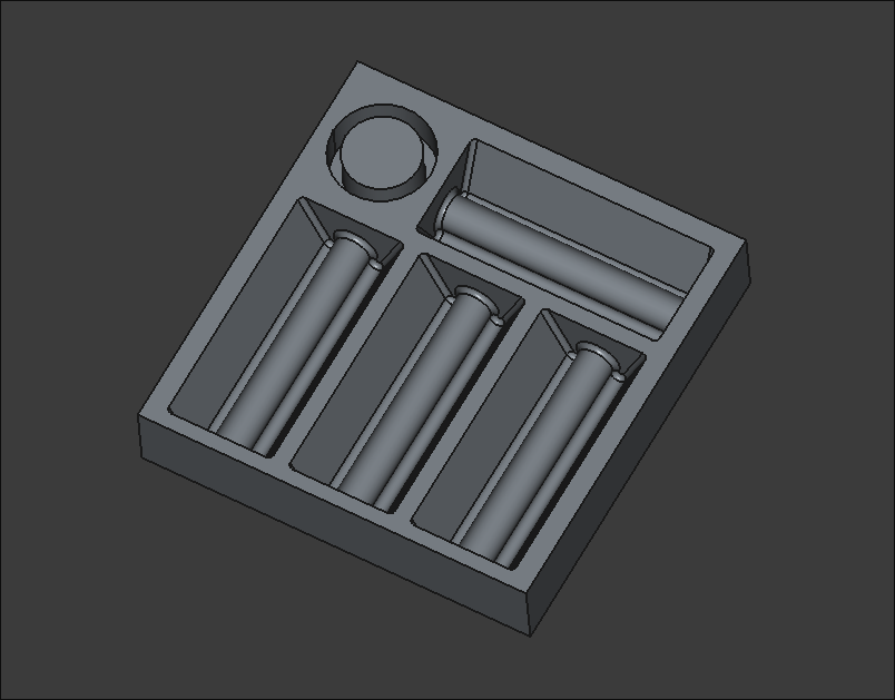
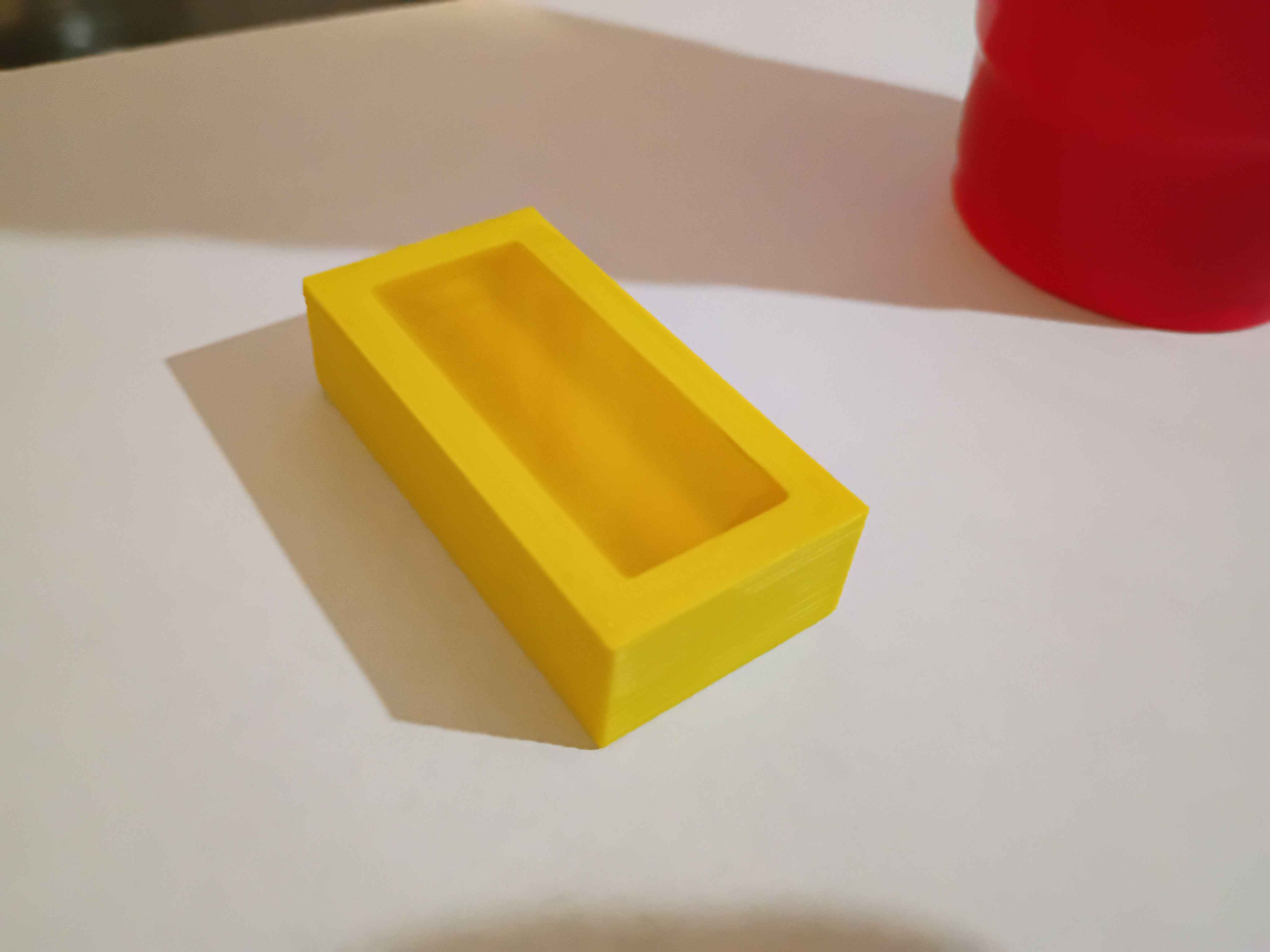
Designed tooling body (01001-001T1) for prototype "PencilHouse" silicone pencil holder (01001-001). Should be printed, smoothed with acetone vapor, and then have Shore 40A platinum cure silicone cast inside it, before being bonded removably to a classroom desk. 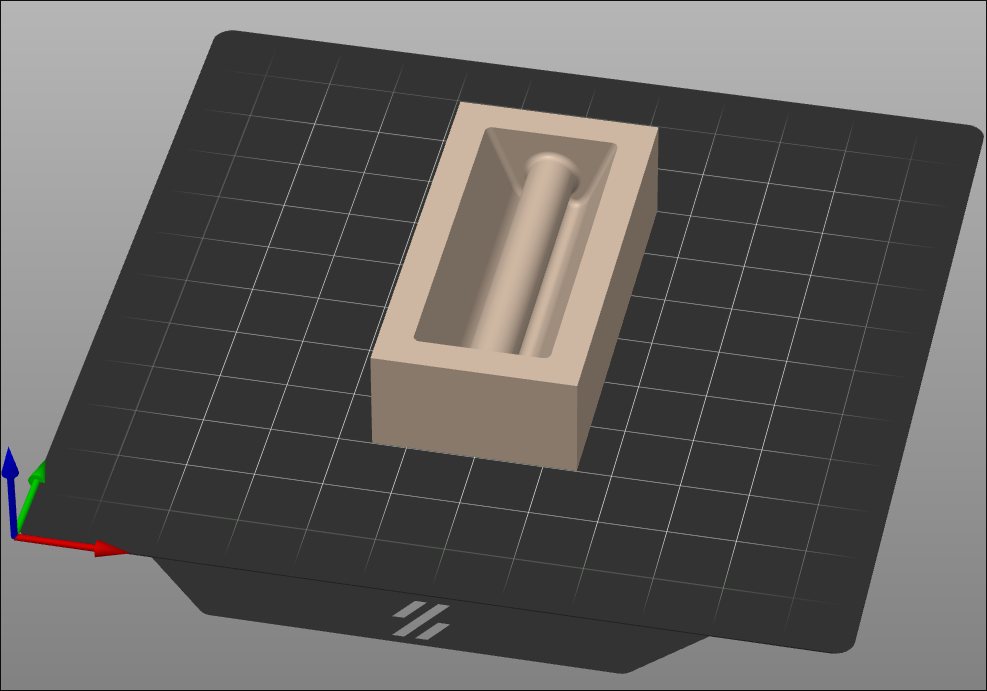
Vibecoded screensaver-esque memory aid for students to become visually familiar with the spelling of sight words.
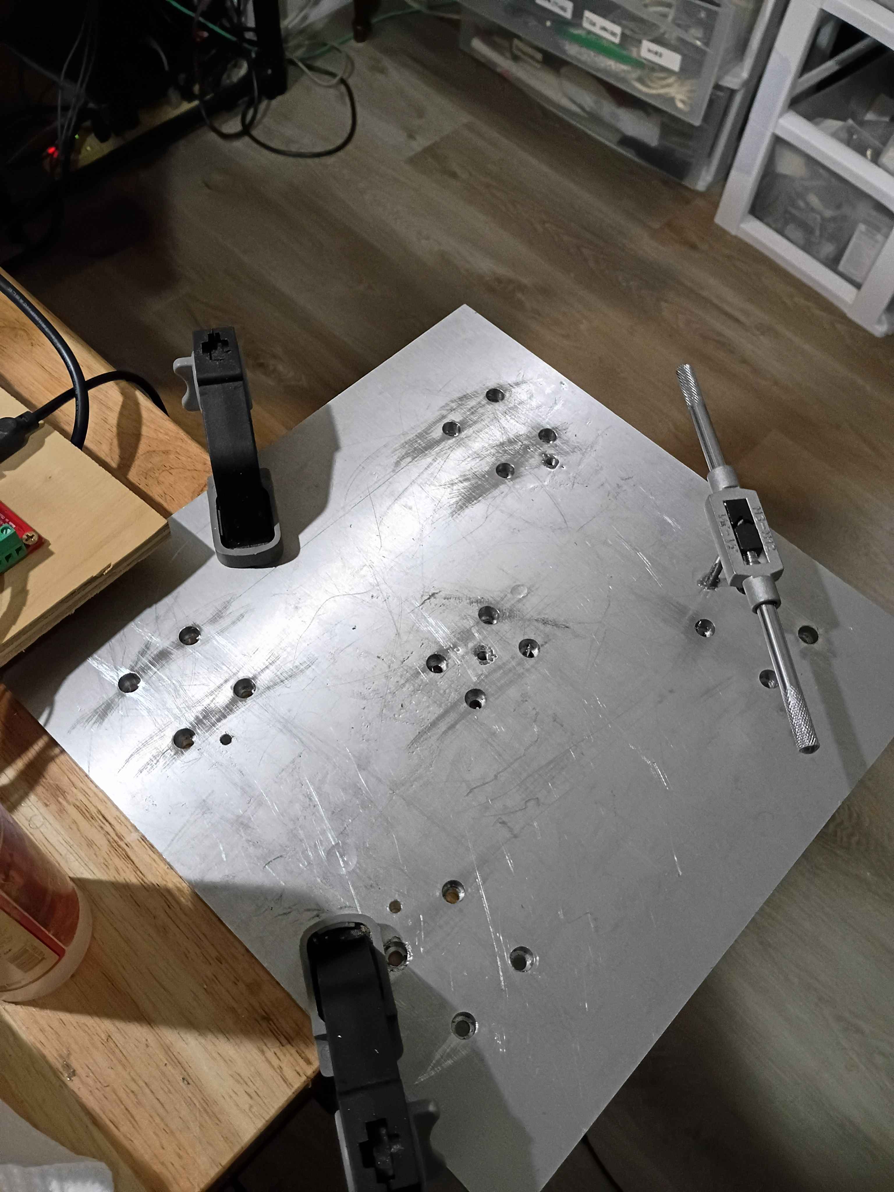
Laid out Z-direction motion components and marked out the hole locations very accurately (hopefully). Drilled and tapped all the mounting points for the rails, the ballscrew supports, and the stepper motor mount. Also drilled and tapped holes for a slightly longer set of rails (for upgradability) and also end stop blocks that can hopefully be 3D printed and would serve as mount points for the limit switches but also prevent the carriages from sliding off the rails in any direction, especially down due to gravity. 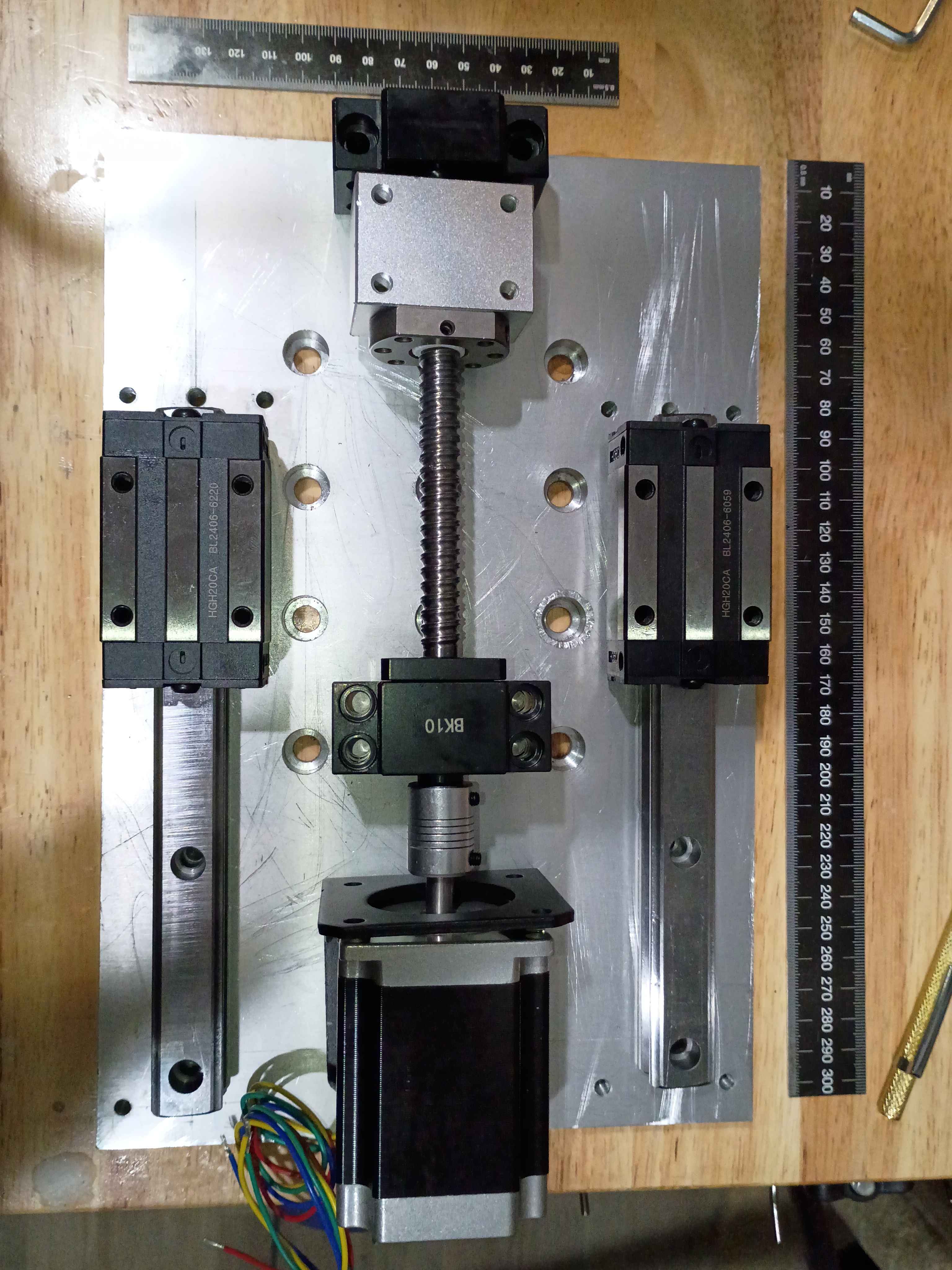
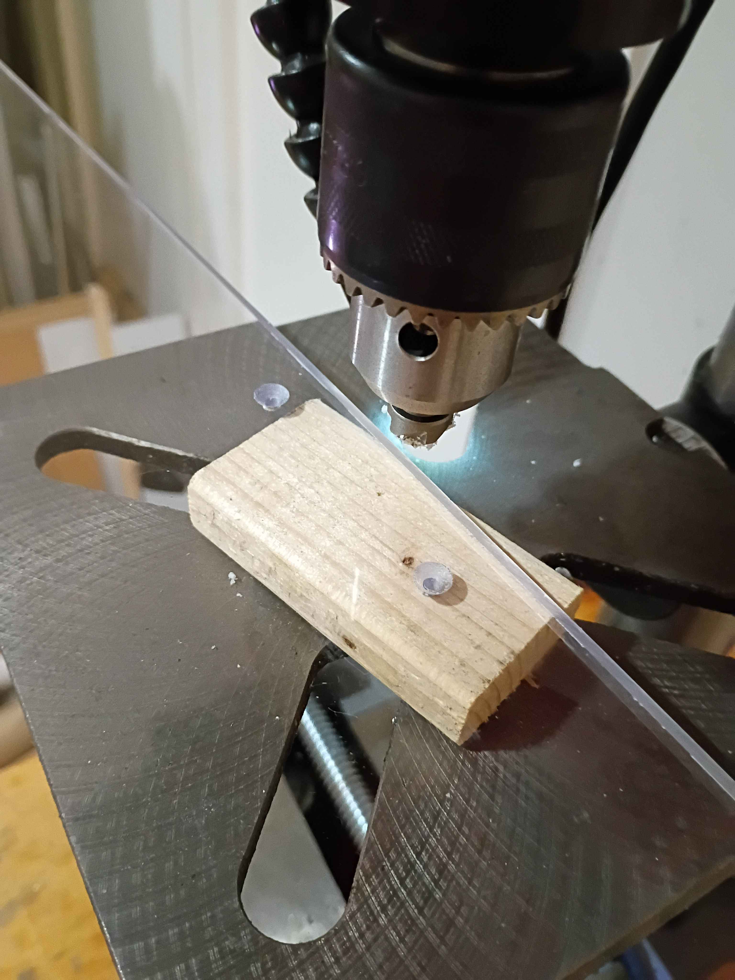
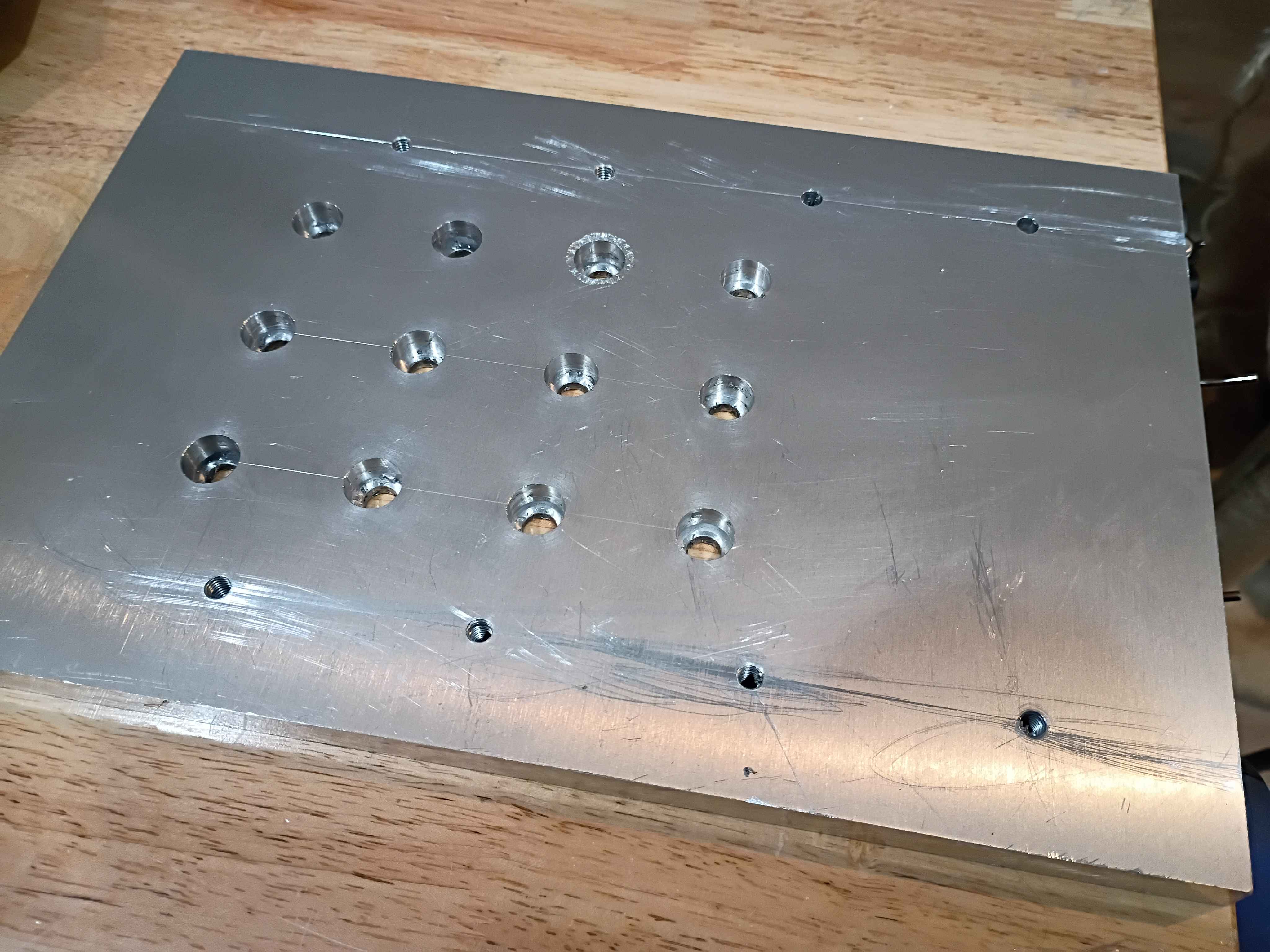
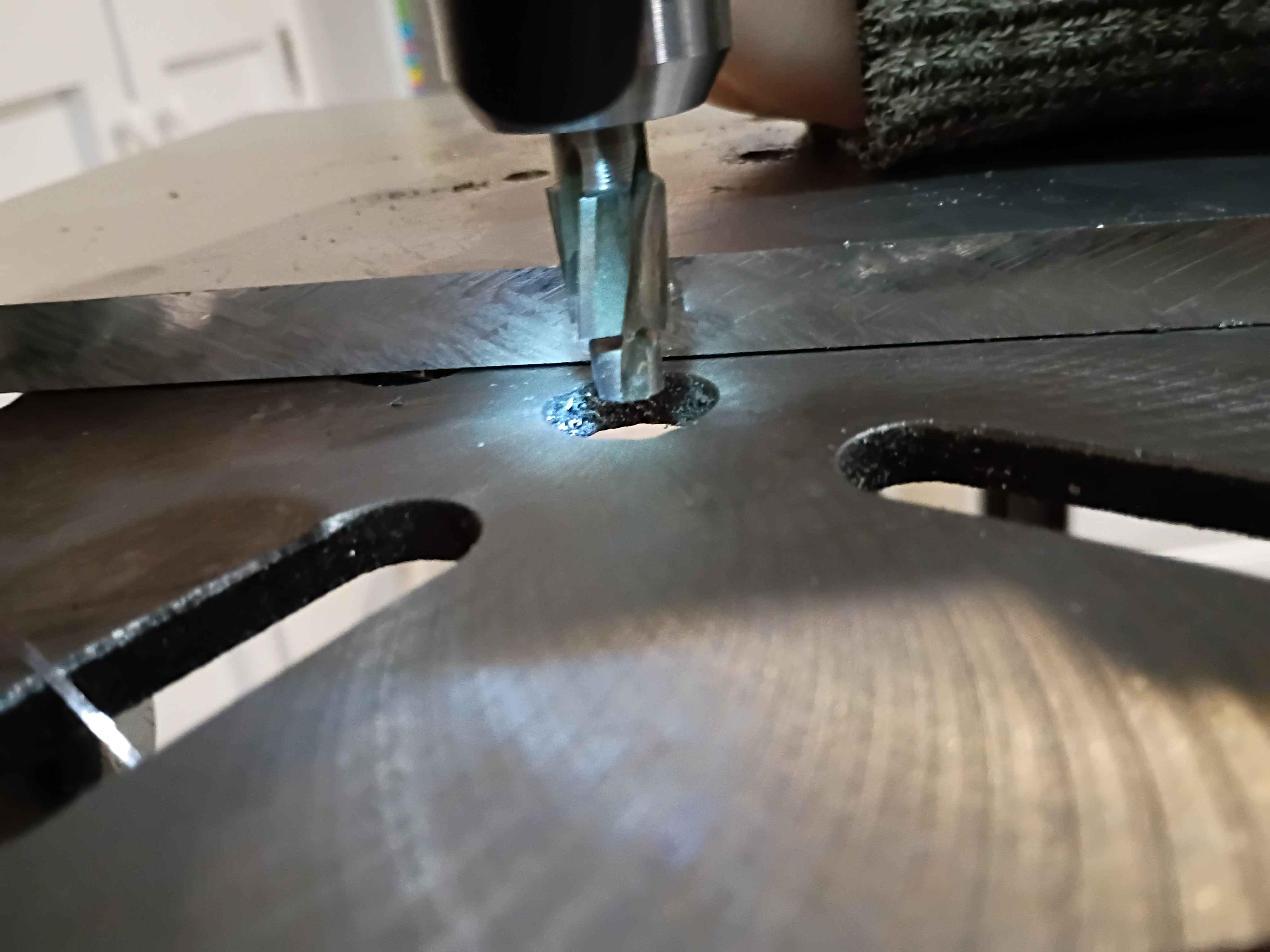
Marked, drilled, counterbored, deburred, and tapped the Z-motion mounting plate. Unfortunately I accidentally did tapped for M6 screws instead of M5, which are the largest that fit in the linear rail holes, so I will need to drill and tap another array of these outer holes, slightly offset from where I made them. Also, learned that you can depress the drill press and counterbore bit on the edge of the part to set the end stop depth appropriately, see last picture. 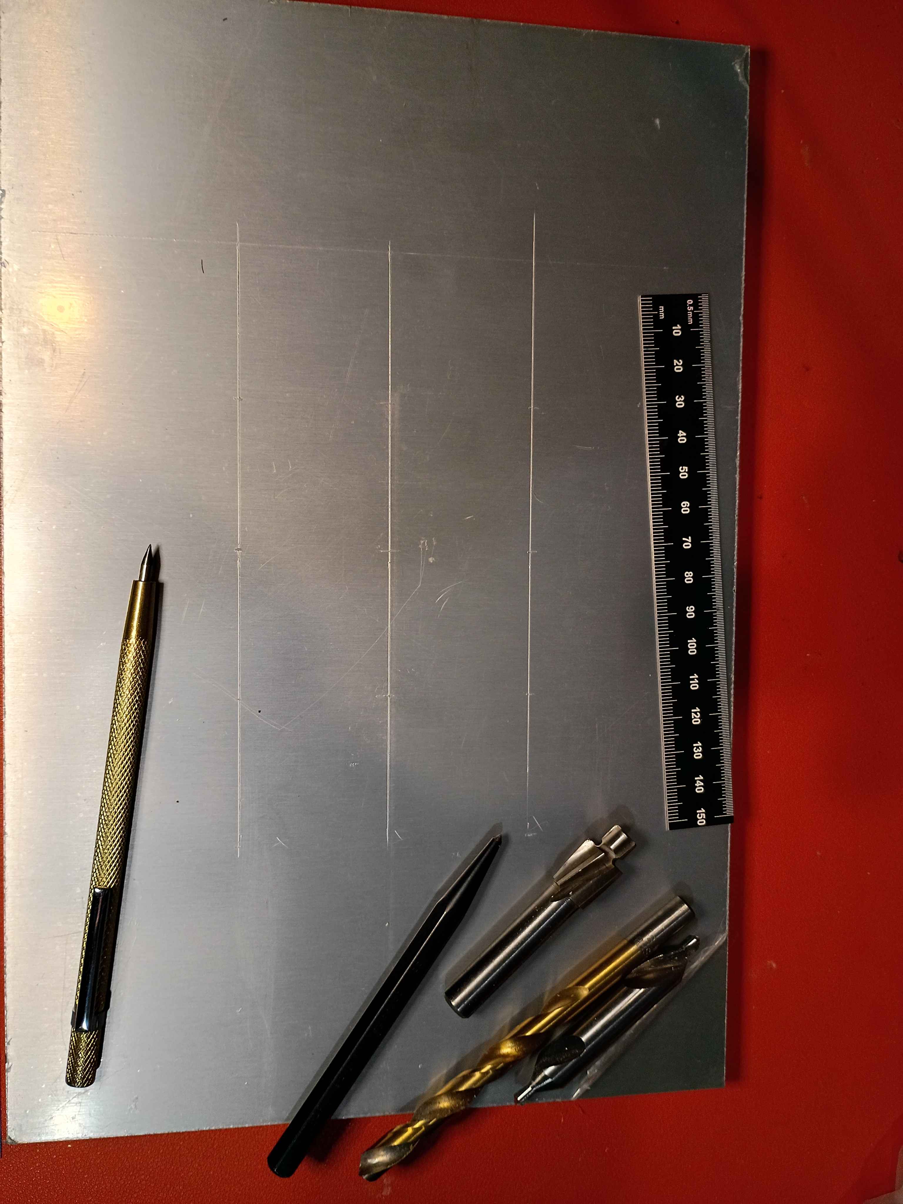
Got OBS websocket working for Twitch bot to change things on the screen. 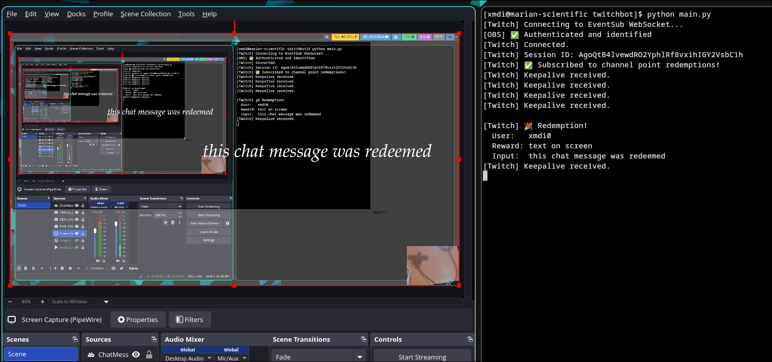
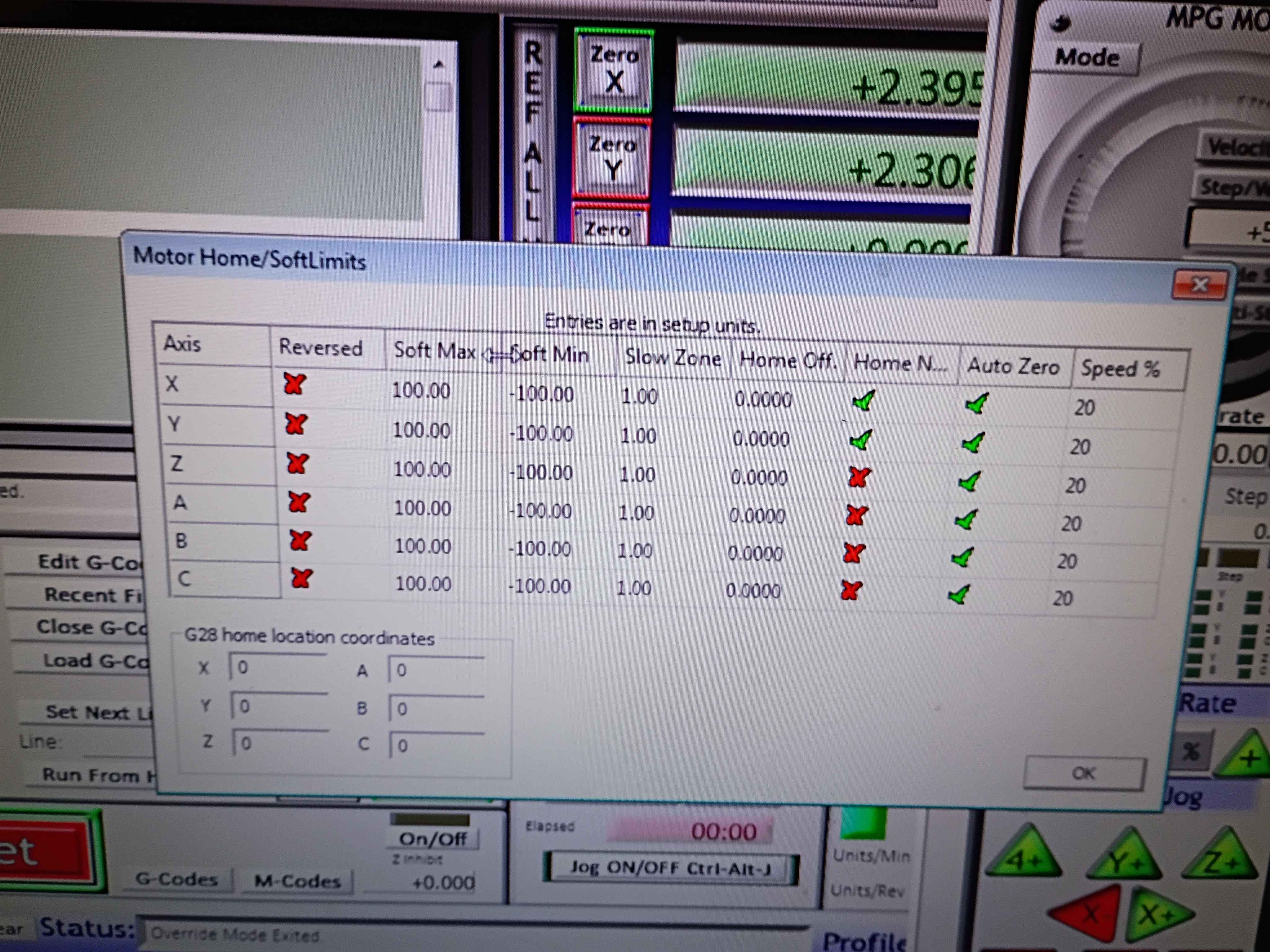
soldered and wired both y-axis limit switches in series NC between GND and the input pin. Got the Mach3 CNC software to recognize and work for both the X- and Y-direction for limit stopping and homing. The below images show the settings which were not easy to determine. See video of limit switches working. I should eventually redesign the x-limit switch mounts to get some more range of motion. Currently there is only like 3.5 inches in each direction. For future reference, Tab opens the jog menu in Mach3, the Settings tab (Alt+6) lets you override the limits to get unstuck, and the Diagnostic (Alt+7) tab shows pin states among other things. Also port 3 is the input pin port on the RNRMotion DLL and board. 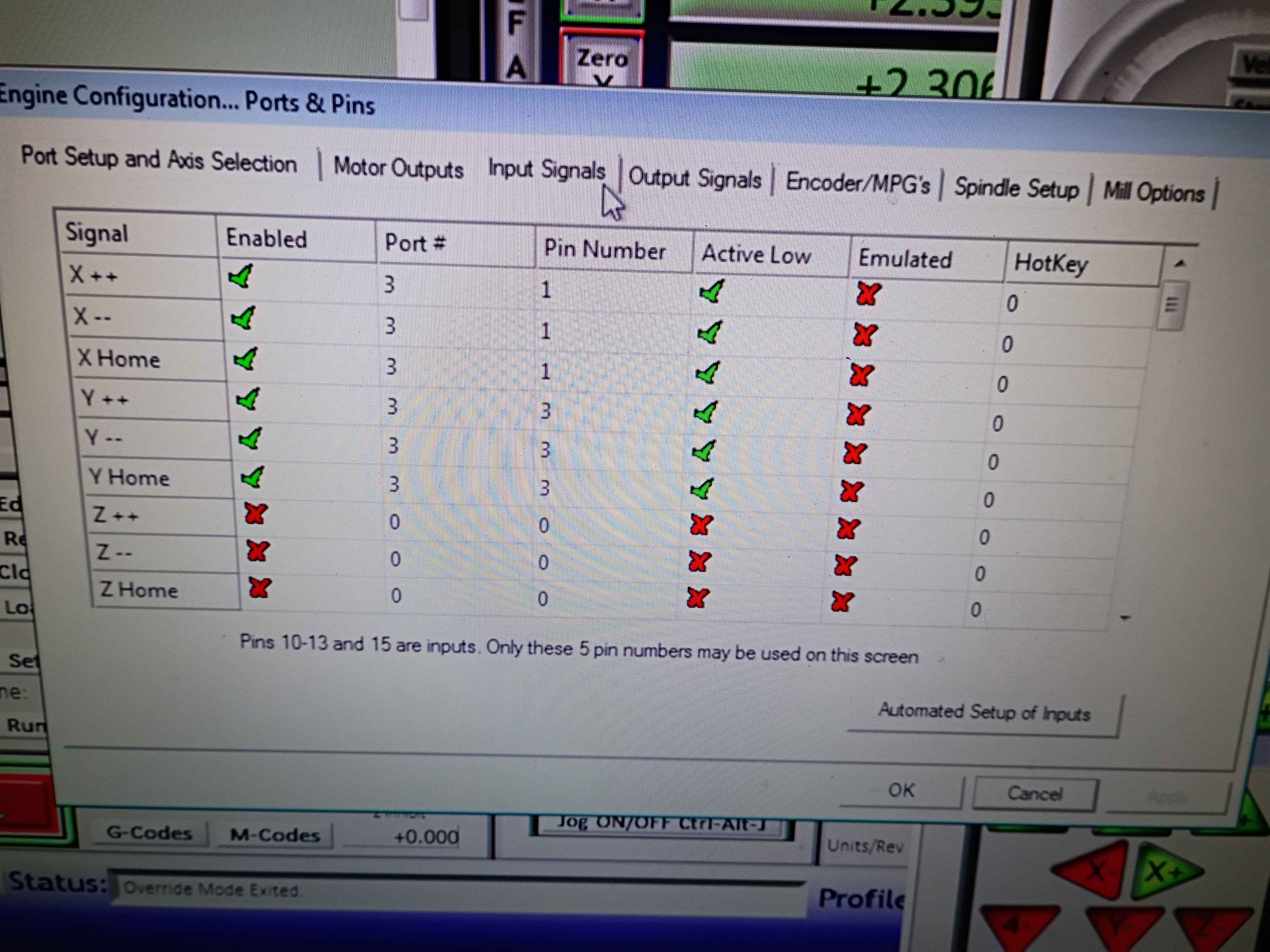
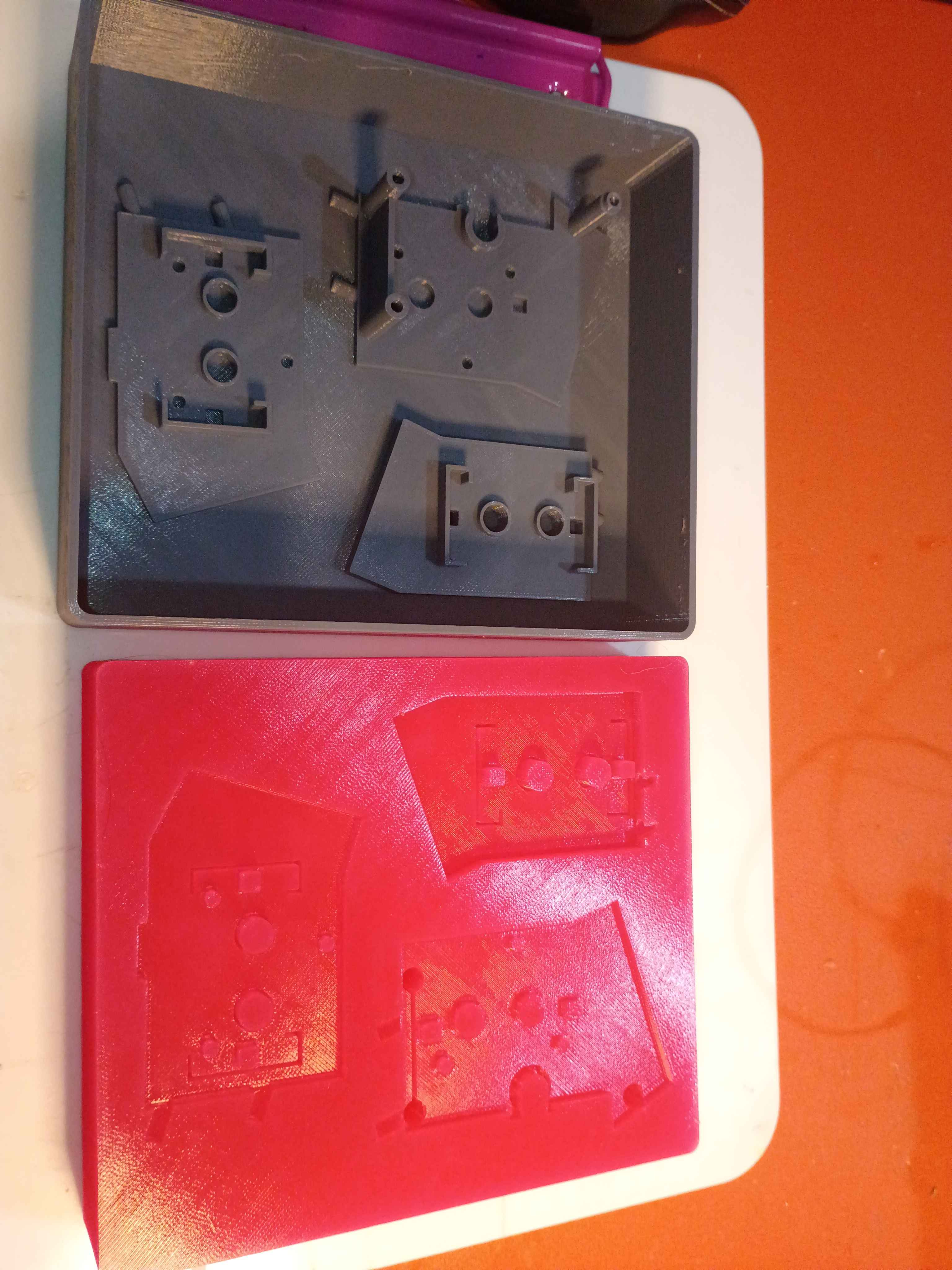
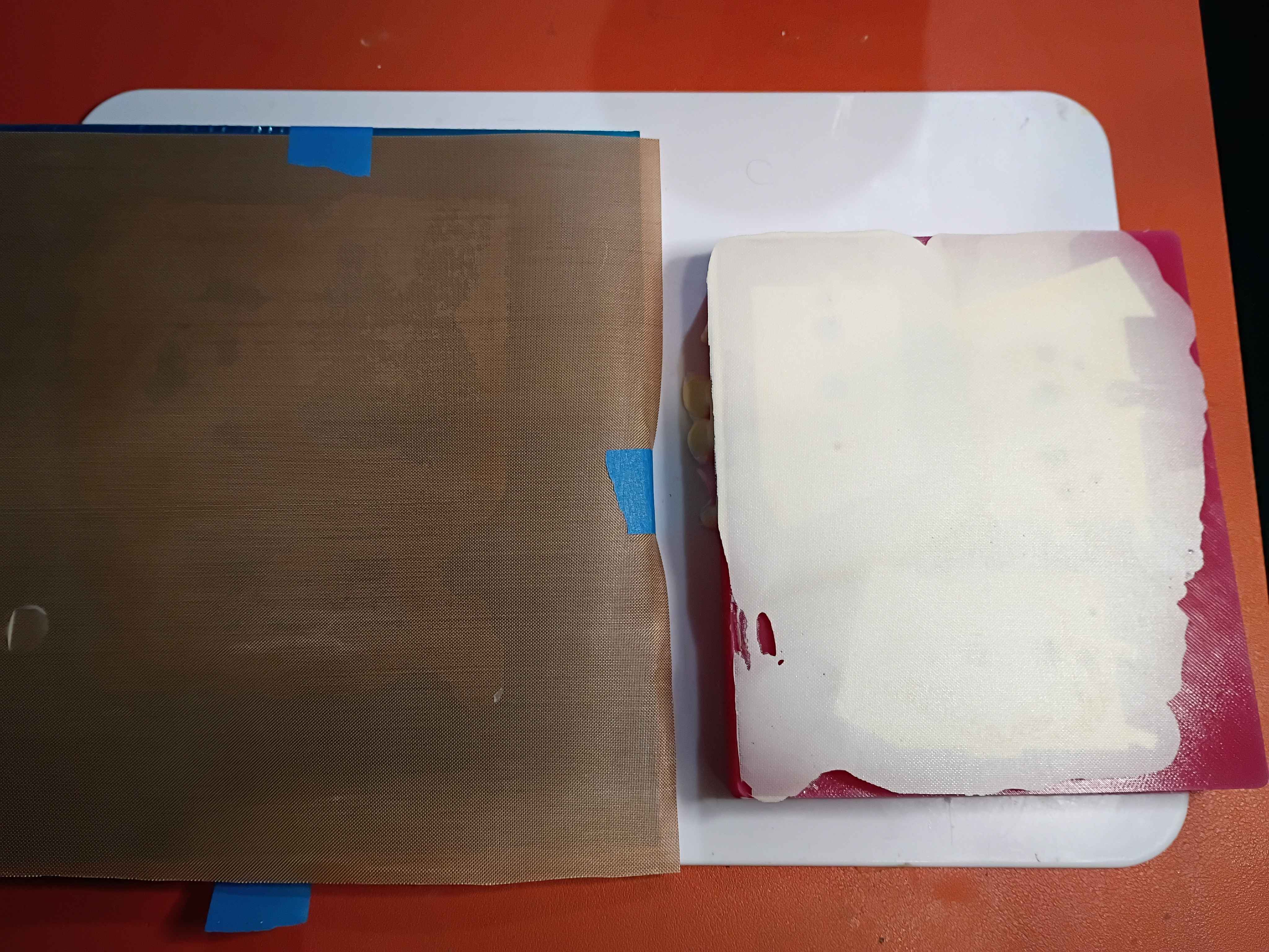
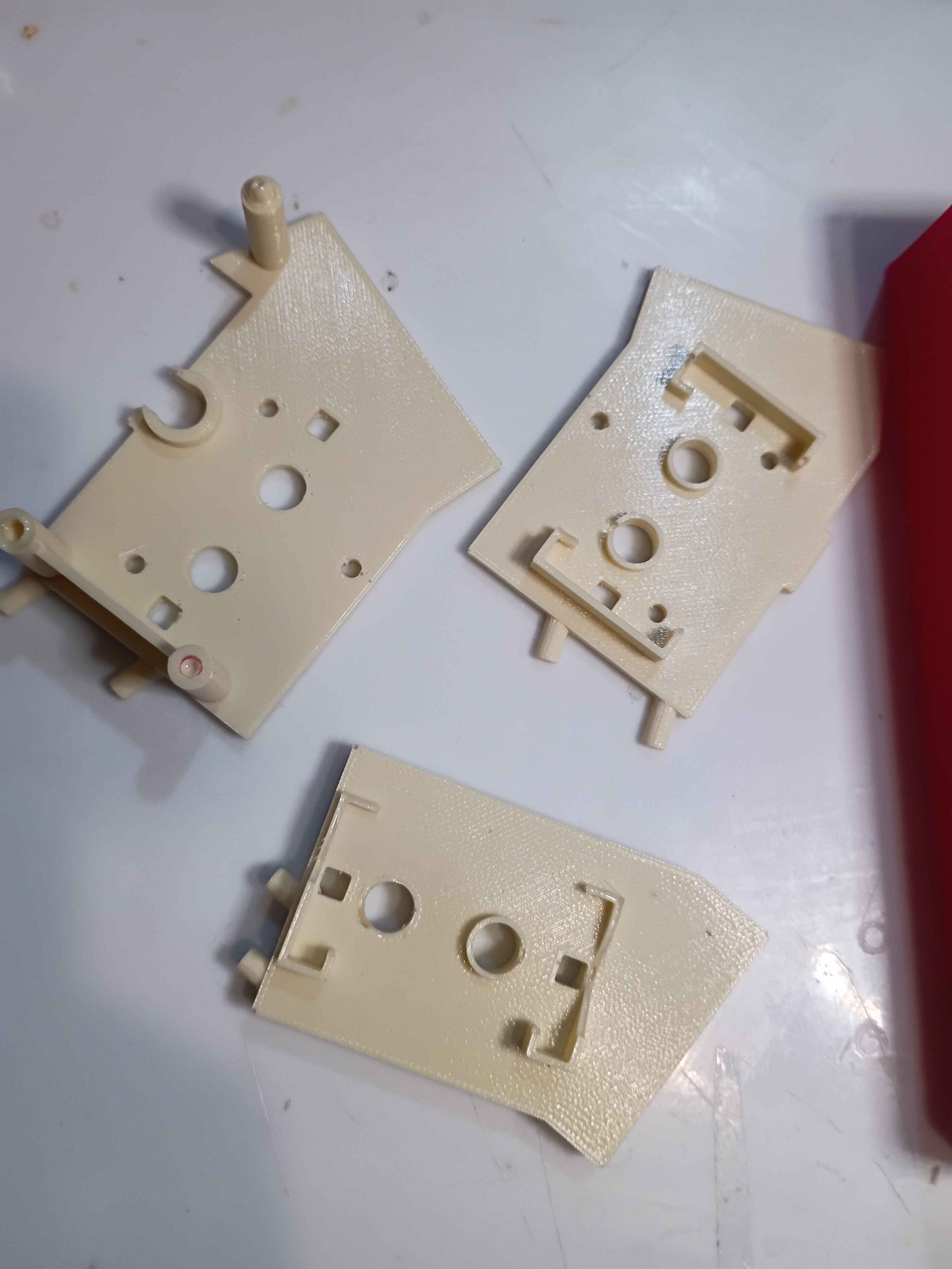
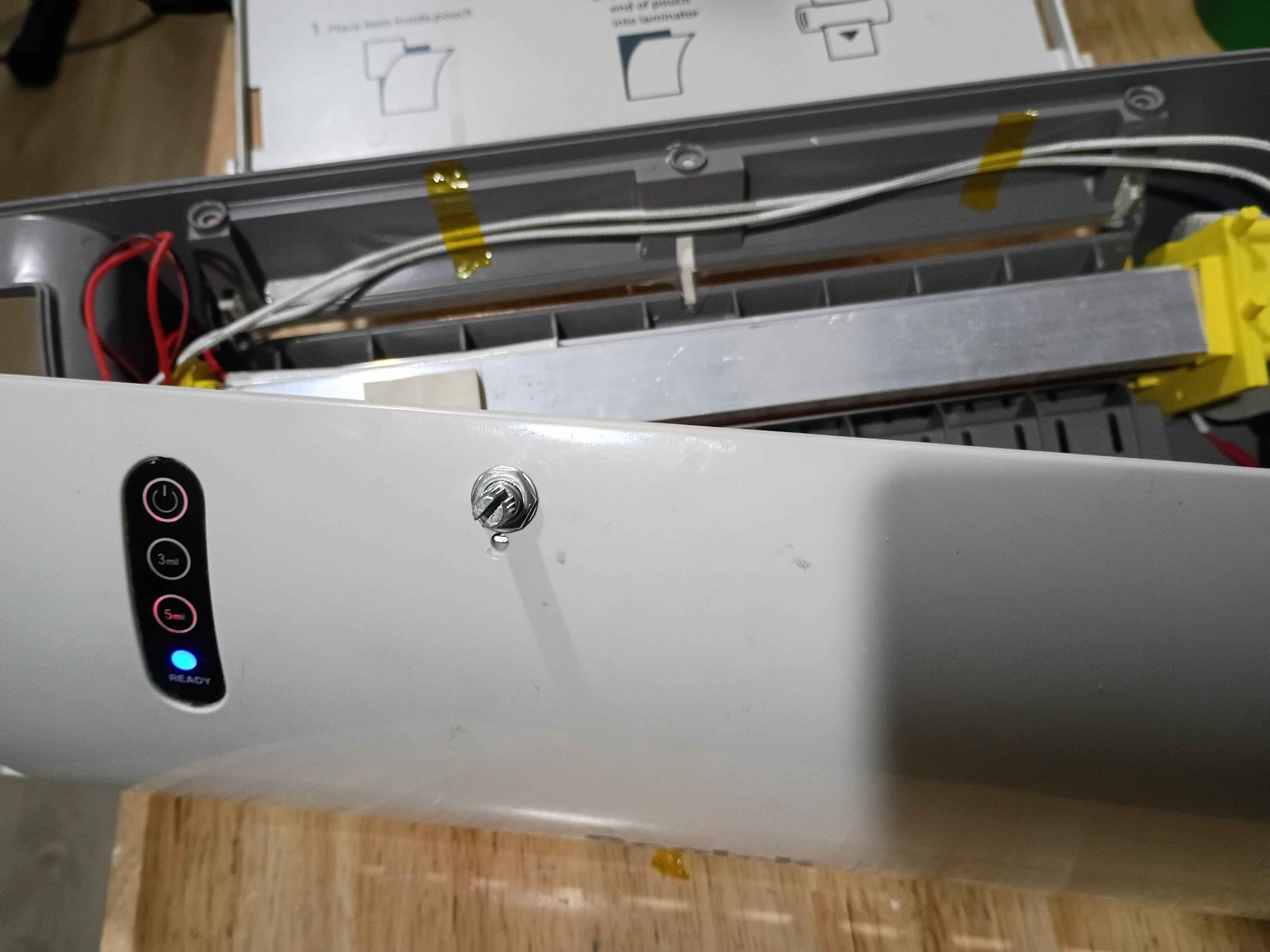
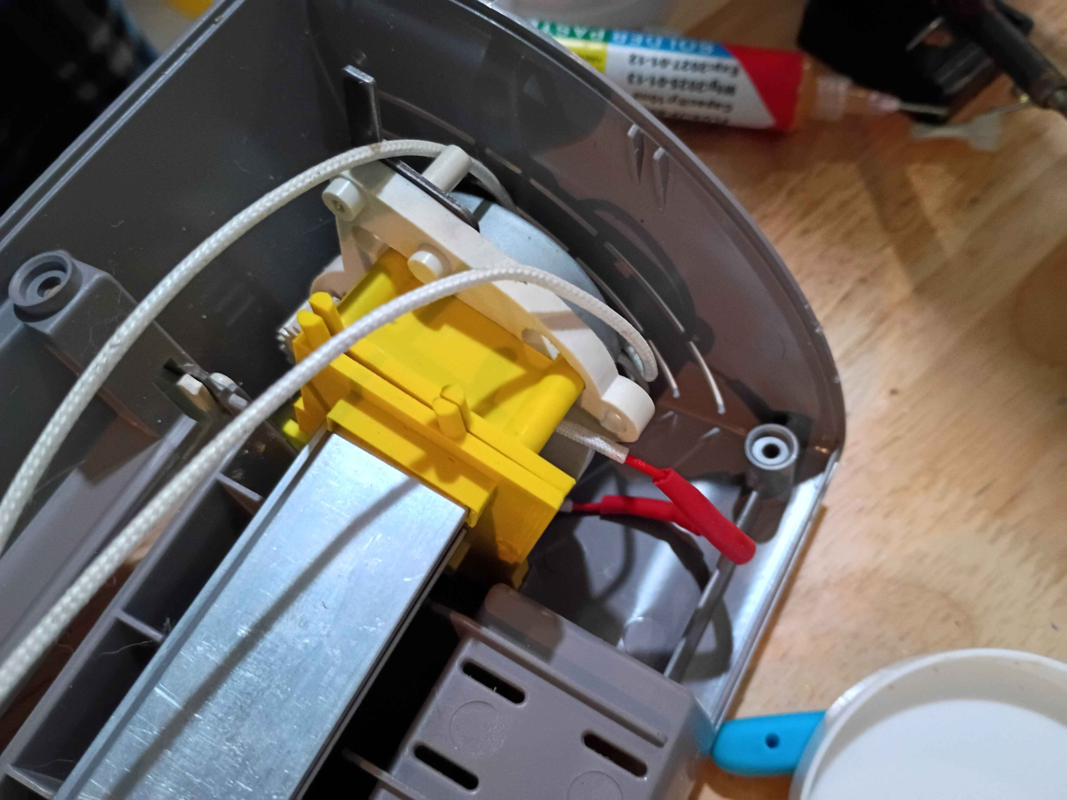
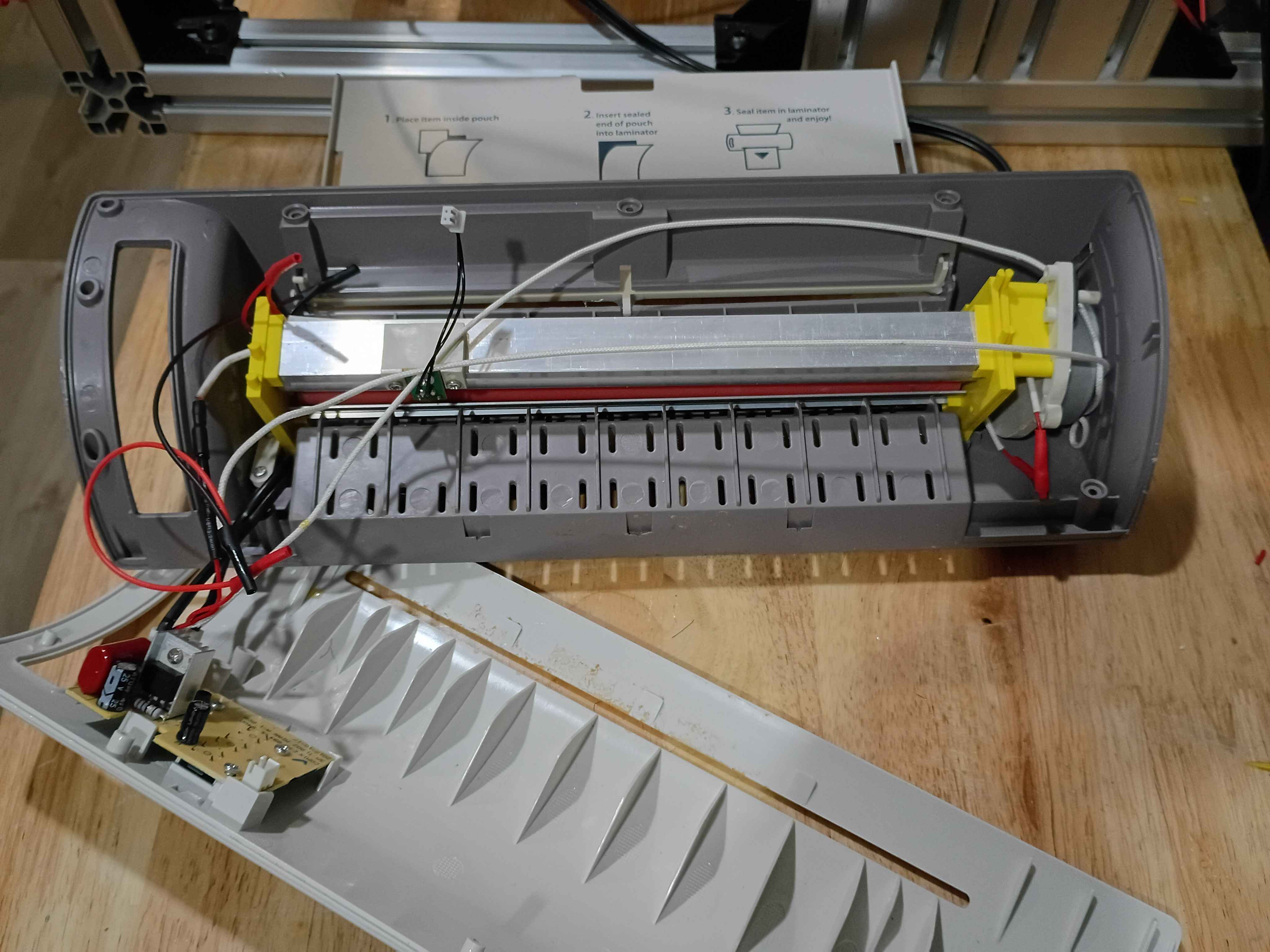
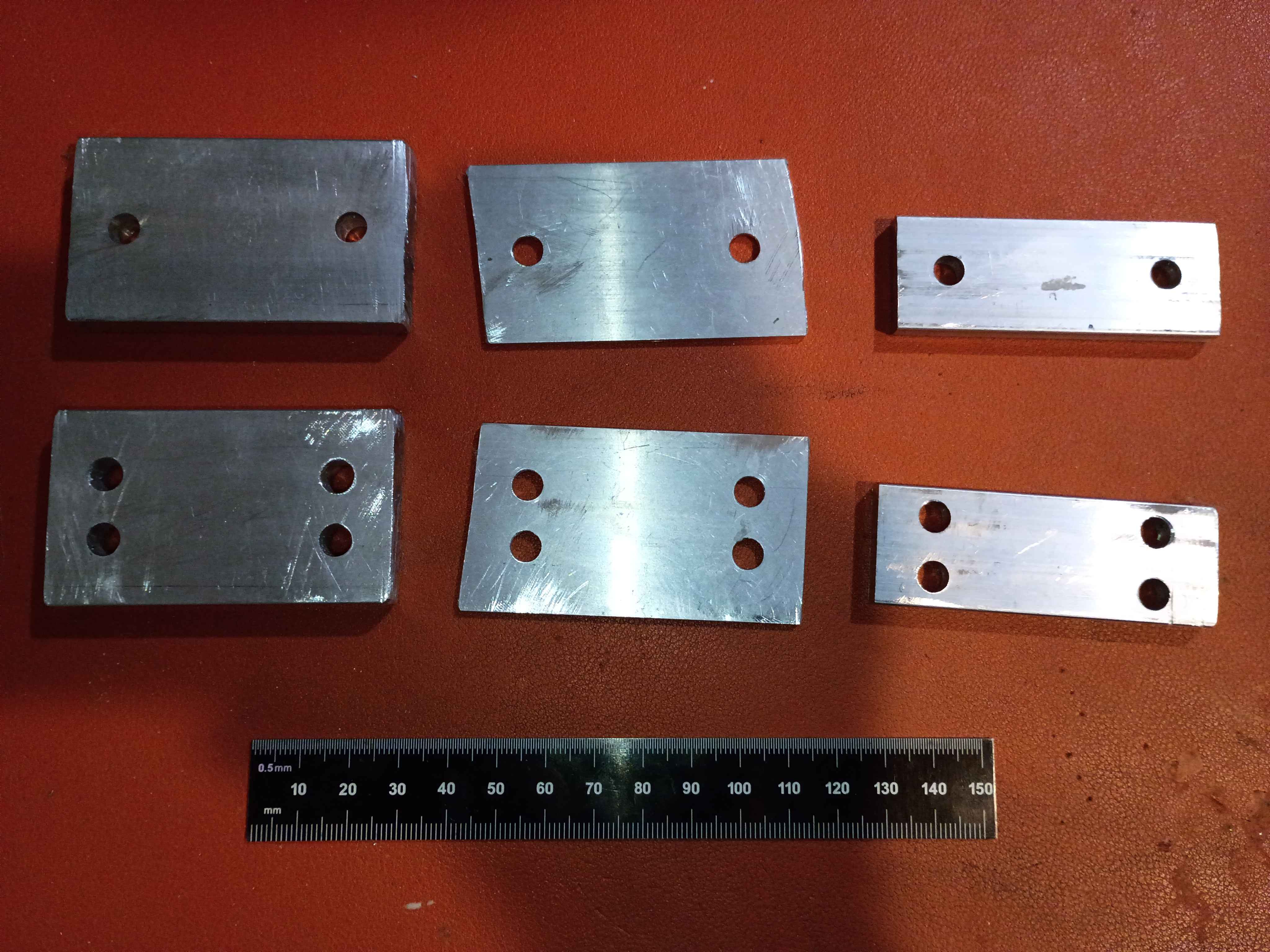
Removed silicone mold from plastic mold and casted the 3 bracket pieces. Used a Teflon mat against an aluminum plate as an upper caul surface which worked amazingly, though it did add roughly .4mm to the part thickness. Demolded the brackets and cleaned them up with pliers and drilling. Glued the two-part piece together and filed them down as necessary to fit in the laminator. Was very lazy when installing these pieces in the laminator, and did not want to cut any wires and thread them thru. In the future I should put removable connectors on everything instead of solder. Eventually got the laminator mostly back together, also due to the size of the left hand bracket it did not close completely. Either way, it does manage to heat up PCBs to close to 200 degrees Farenheit. I also should have made 3x separate silicone molds, as it would have saved a lot of silicone. In addition, some small features at the bottom of the mold cavity did not resolve properly or at all likely due to bubbles remaining on the bottom. This could be fixed by having larger features at the bottom, degassing the polyurethane (hard because pot time is only 2 minutes), or vibrating the mold during cure. Otherwise this entire process was a pretty good success. 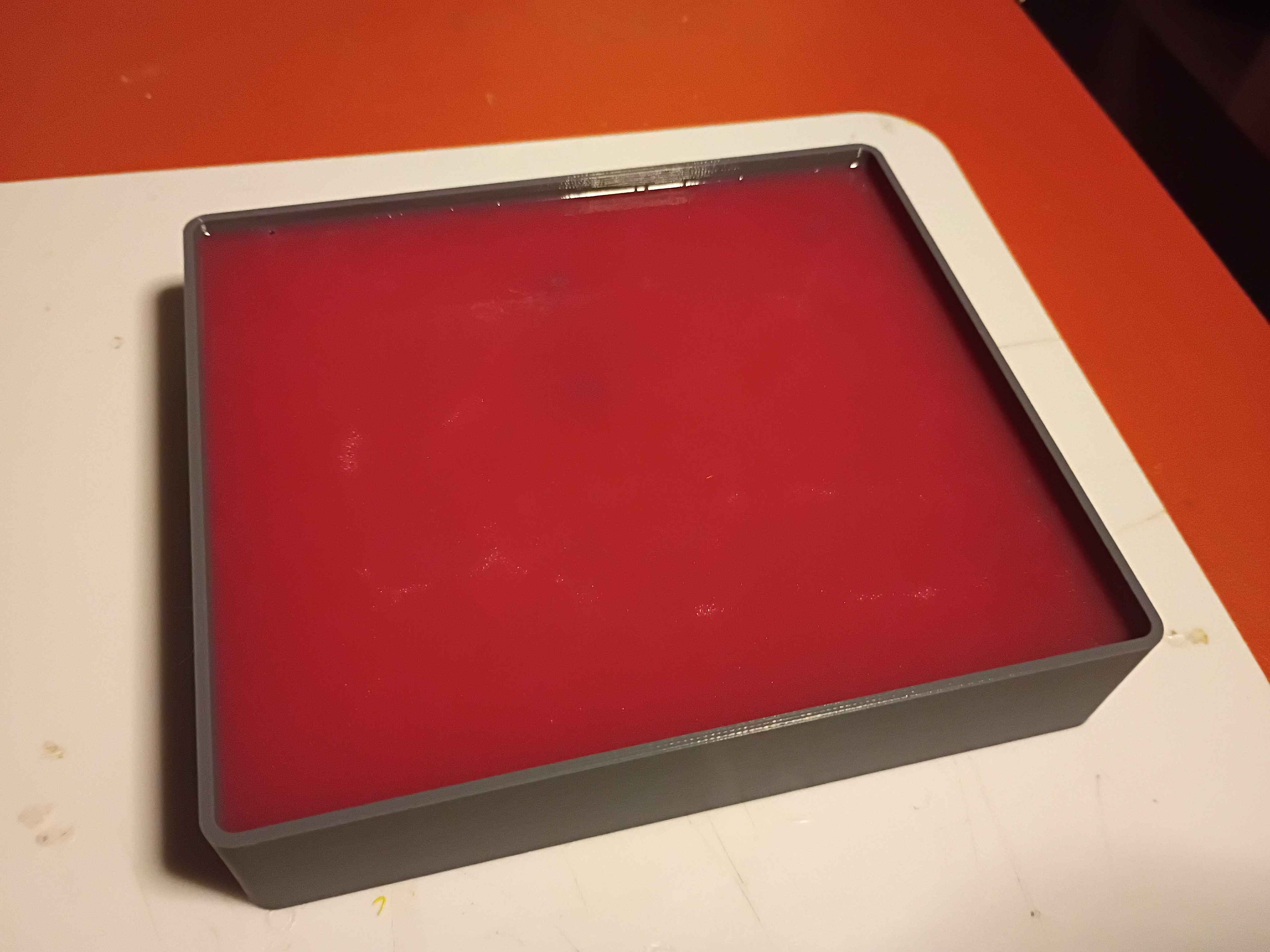
Redesigned and printed 00001-010A. Installed limit switches (unwired), and used friction and hot glue to install both side brackets onto the ball screw support blocks. 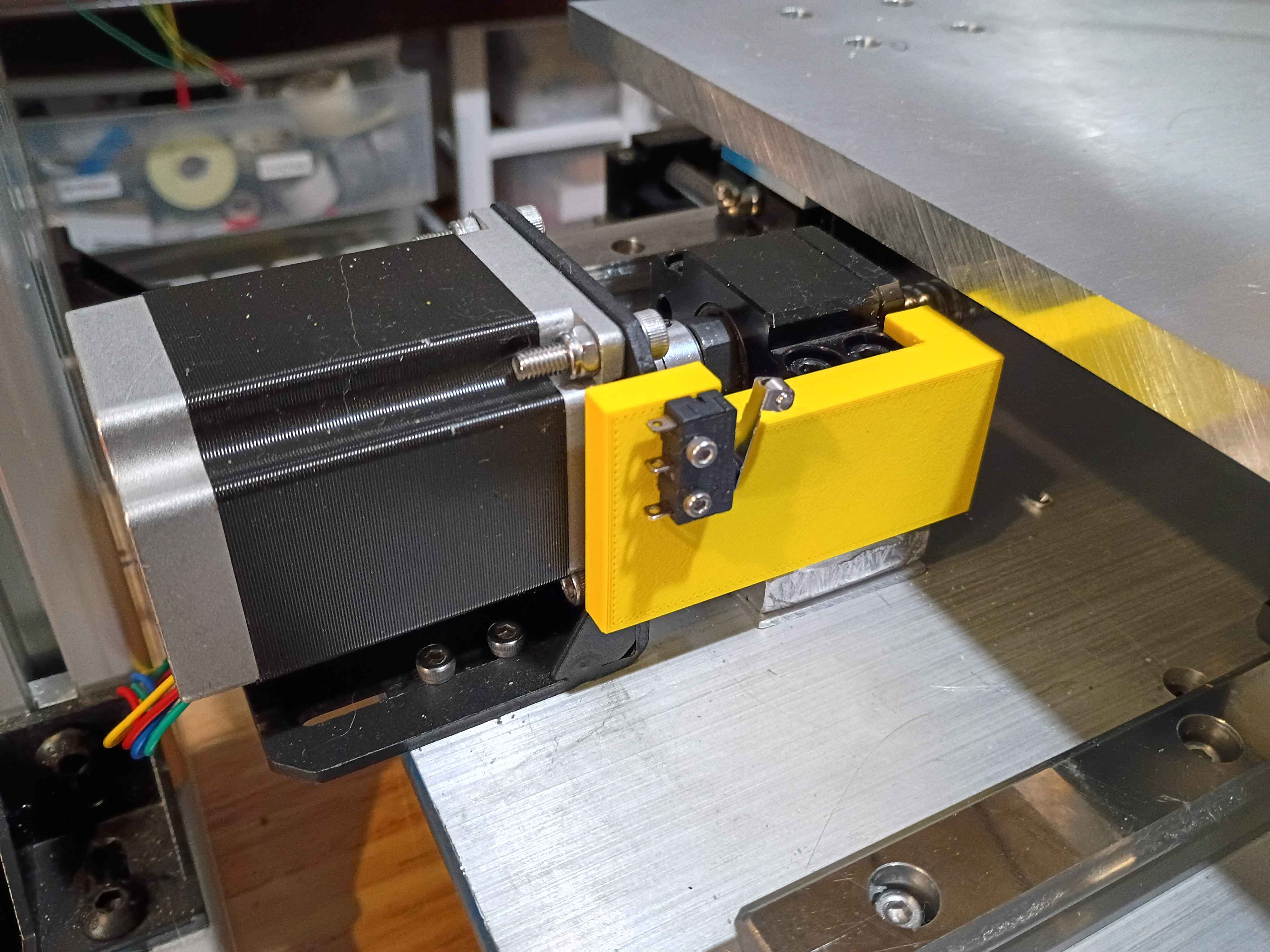
Printed the 00001-009 and installed limit switch successfully into position (unwired currently). Fits perfectly. Designed and printed the opposing 00001-010 part. 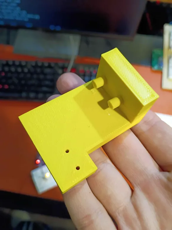
Printed 43001-001T1 mold for negative silicone mold, to eventually be used for heat-resistant polyurethane. Cast the silicone mold. 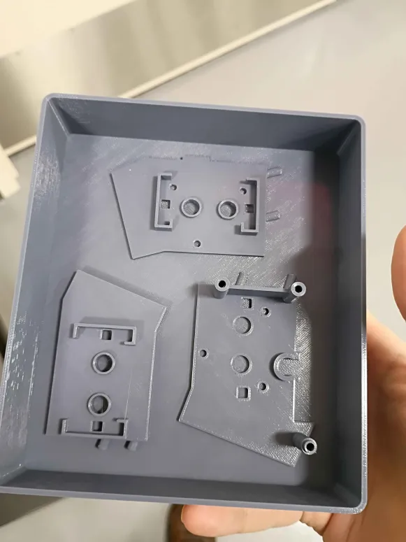
Contributed 2 examples (Python and C) of basic PC-GPIO control using FT232H USB breakout to the sandbox. 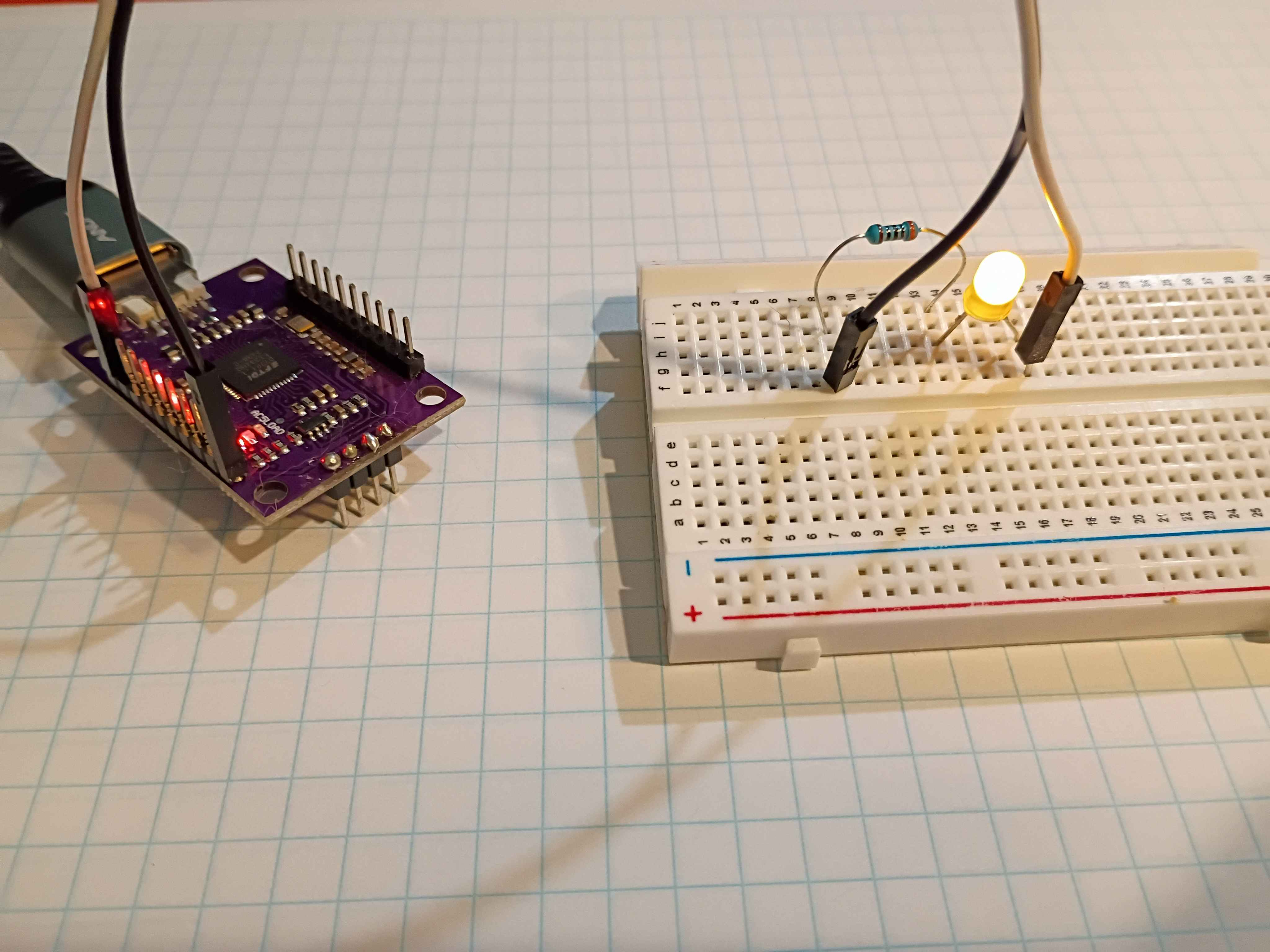
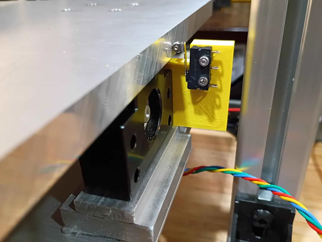
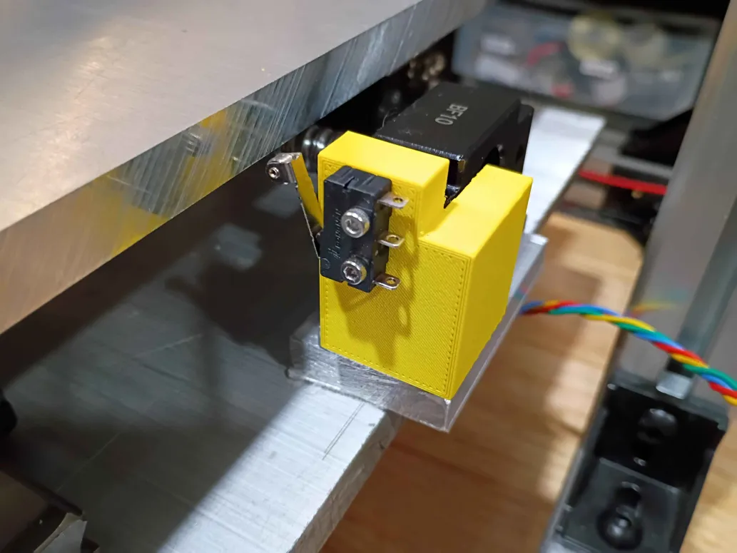
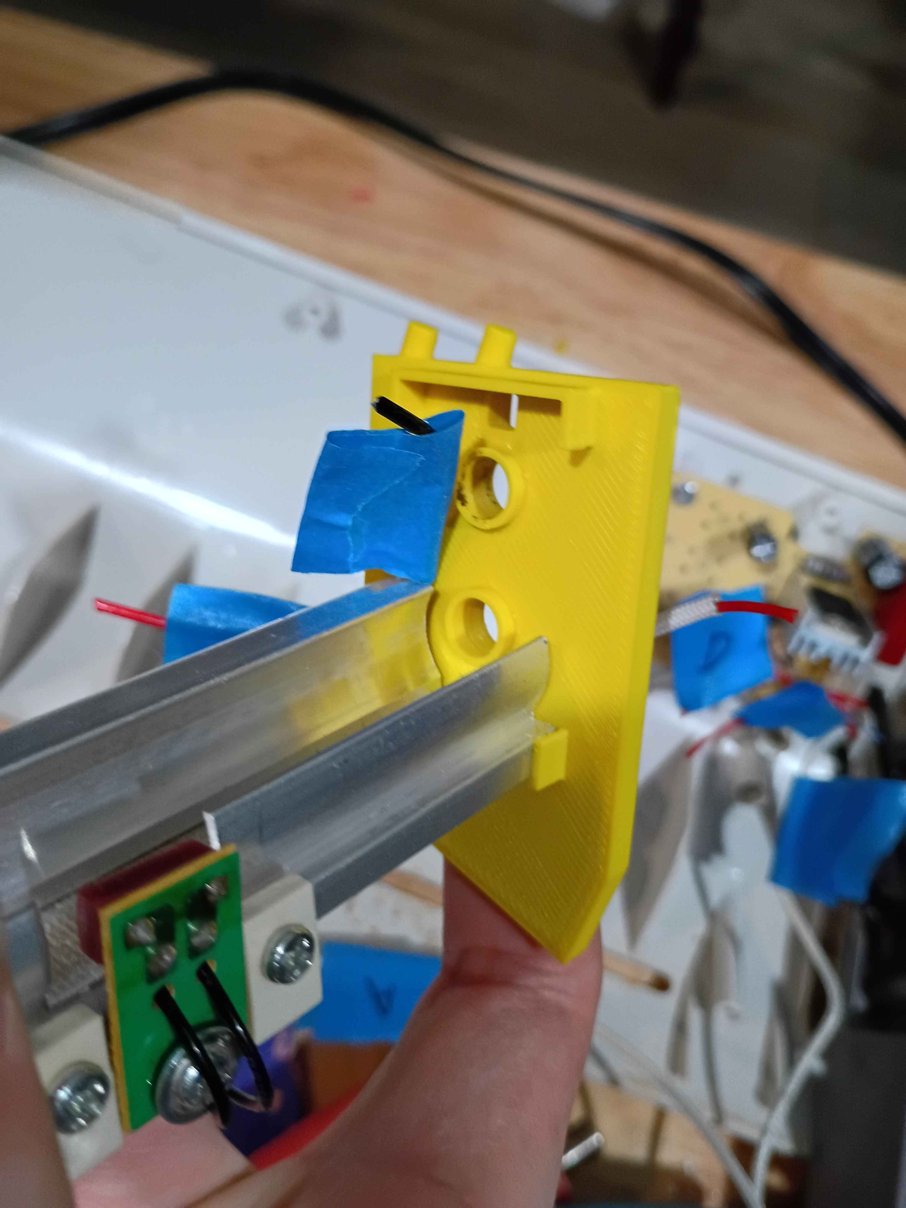
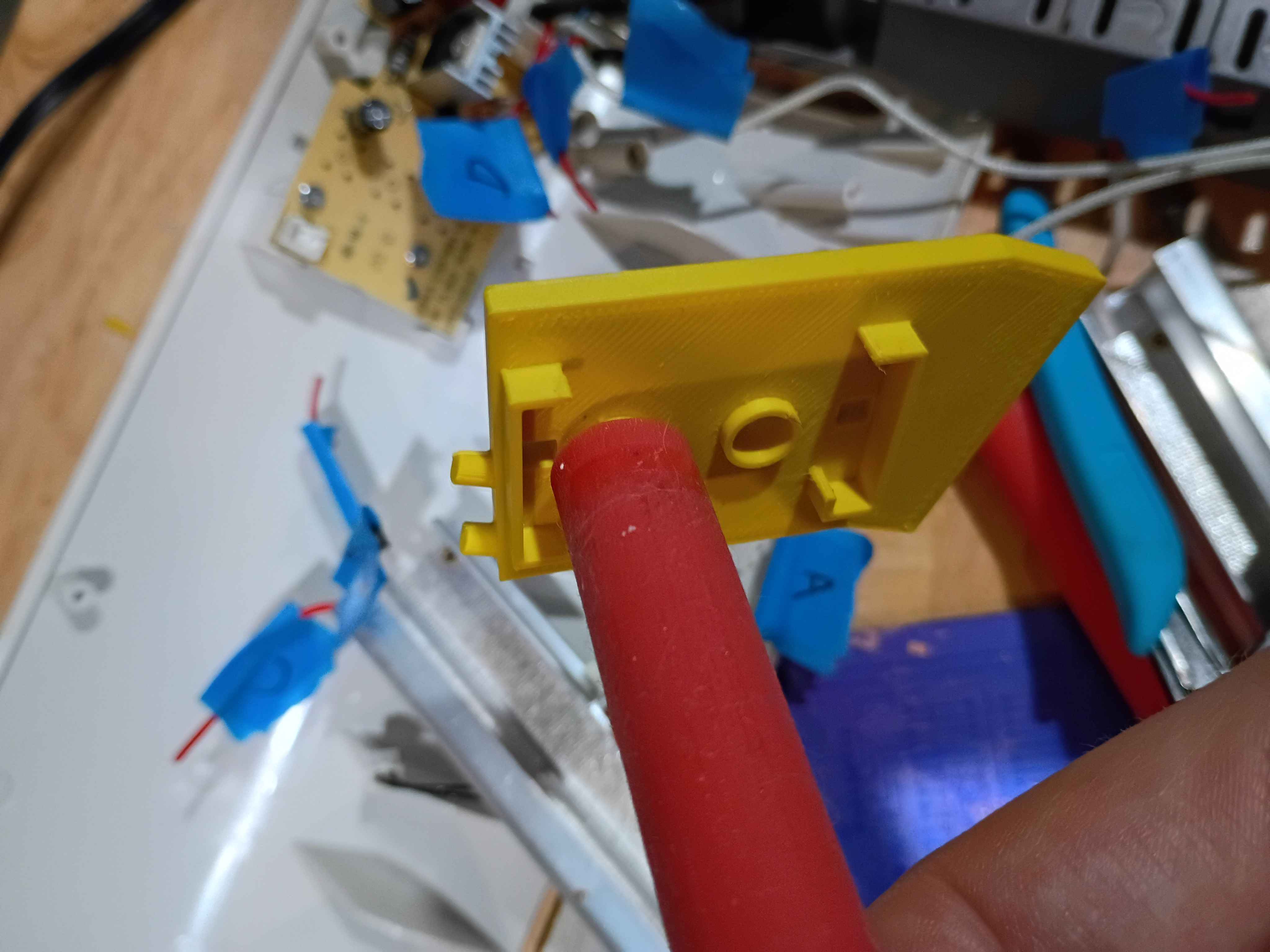
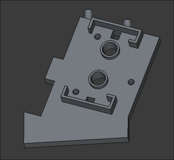
Redesigned limit switch bracket with cutaway for gantry motion. Printed in a different orientation to enable stronger pegs. Will be installed in the opposite orientation shown in Figure 2 below. Currently another design iteration is being printed that maximizes the range of motion along this axis. Due to the asymmetry on the ballscrew supports, a unique but similar part will be required on the opposing side. 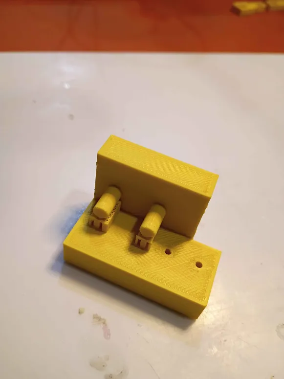
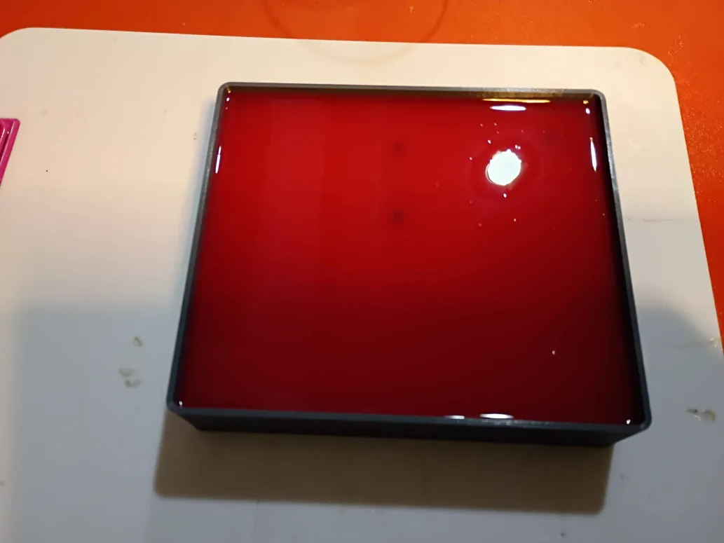
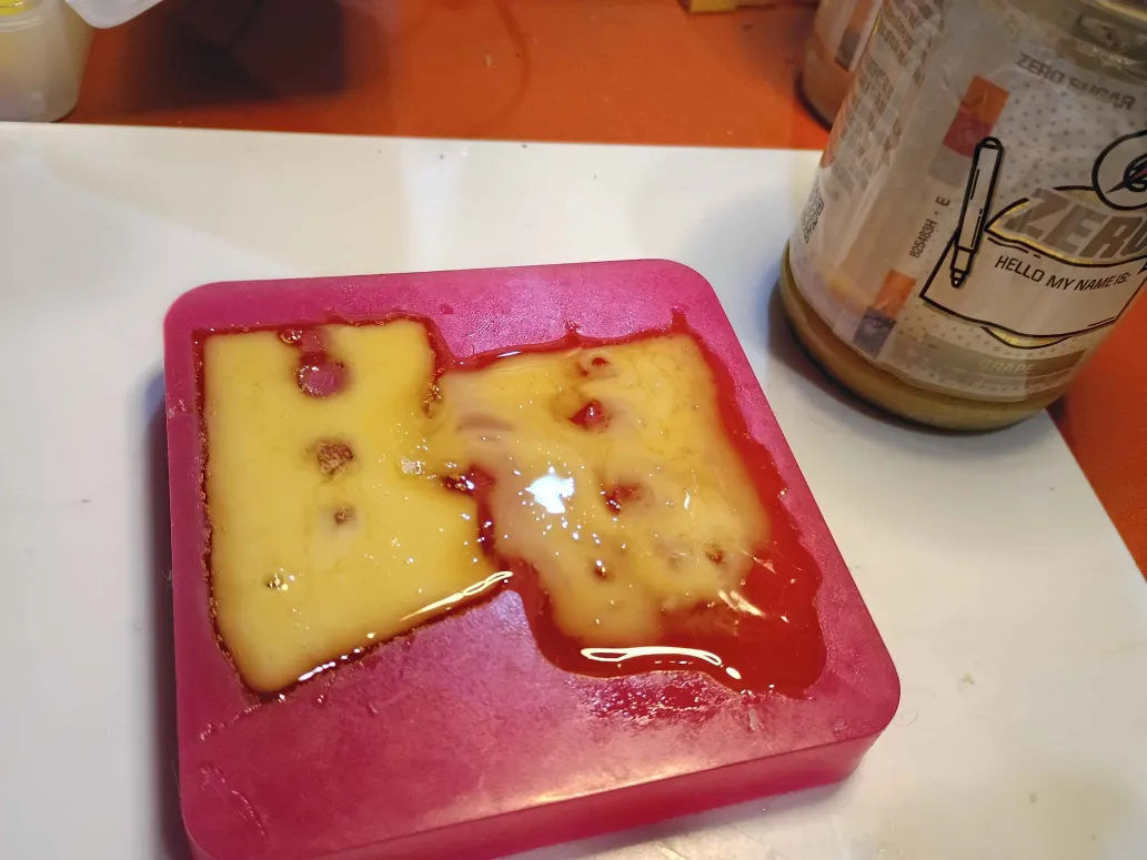
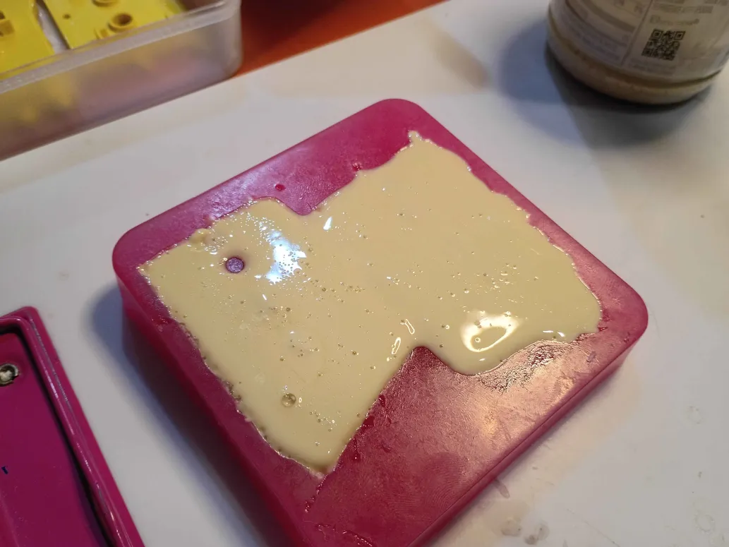
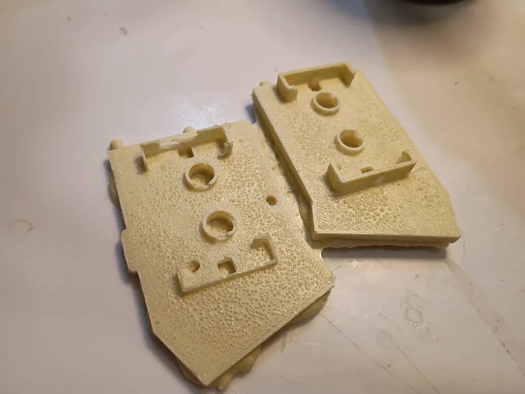
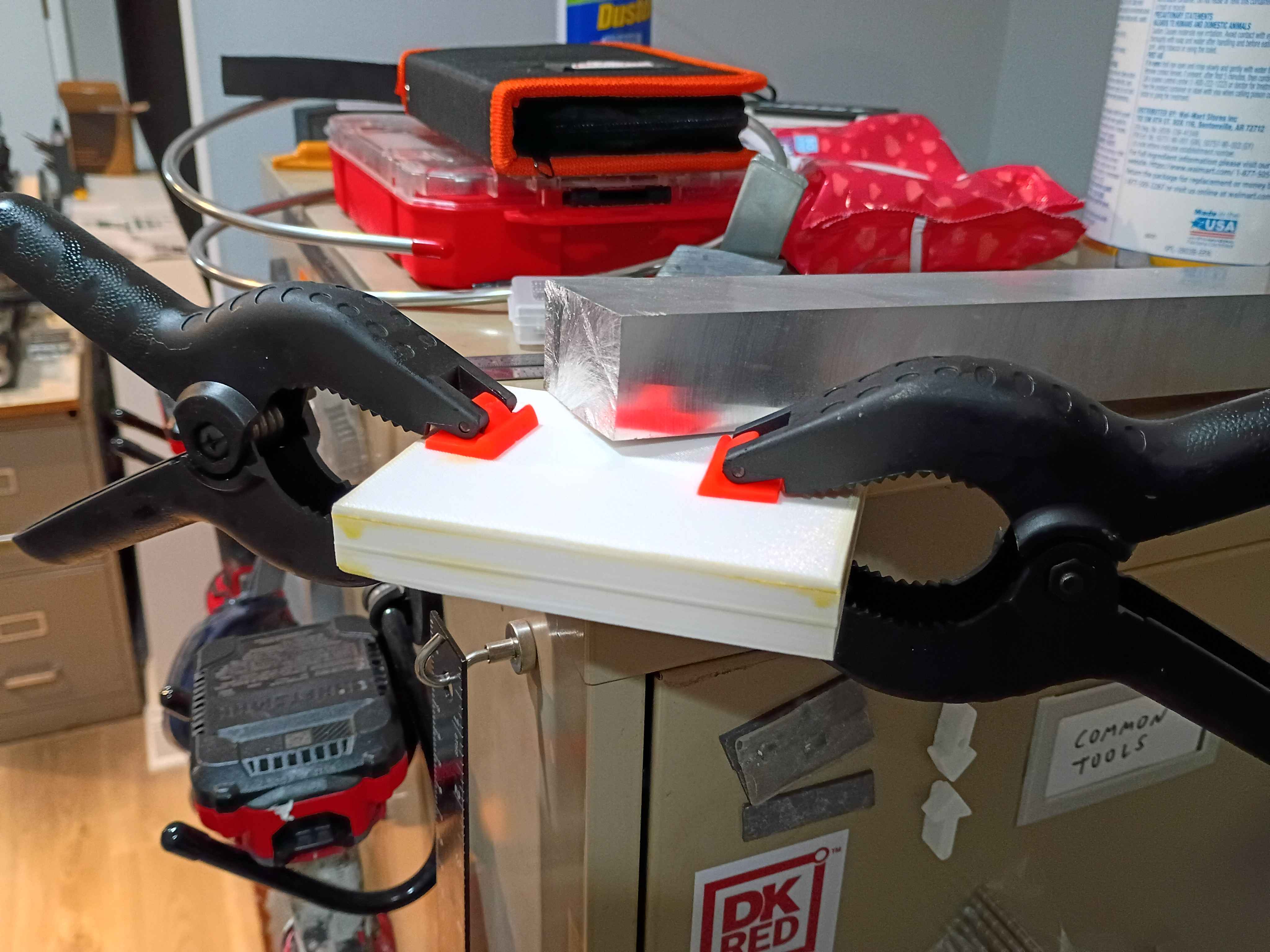
Demolded negative silicone mold, cleaned up edges using razor blade and tweezers. Note that for open-top silicone molds, it is important that there be no way for silicone to find its way between the part and the 'bottom' of the mold. Poured Smooth-On Task 8 heat resistant polyurethane resin into the mold, and it cured in around 10 minutes, getting quite hot in the process. The parts turned out as well as one could expect for a first attempt and a pretty mediocre silicone mold. The parts filed extremely cleanly. The parts did bulge at the open faces, but that is relatively easy to sand flat against a file. I noticed a small geometrical error and decided to design a full 1-piece mold-box combo for all the 3 parts, to be printed tomorrow. 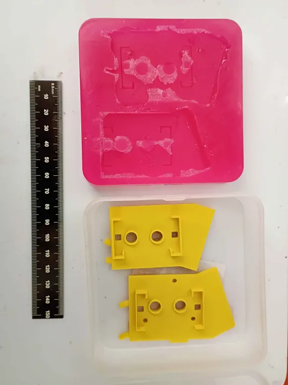
Designed and printed first iteration of y-axis limit switch brackets (00001-009). Found 3 geometric characteristics that needed to be revised, and submitted another overnight print. 
Started silicone mold for heat resistant polyurethane bracket components that hopefully won't melt in the laminator. 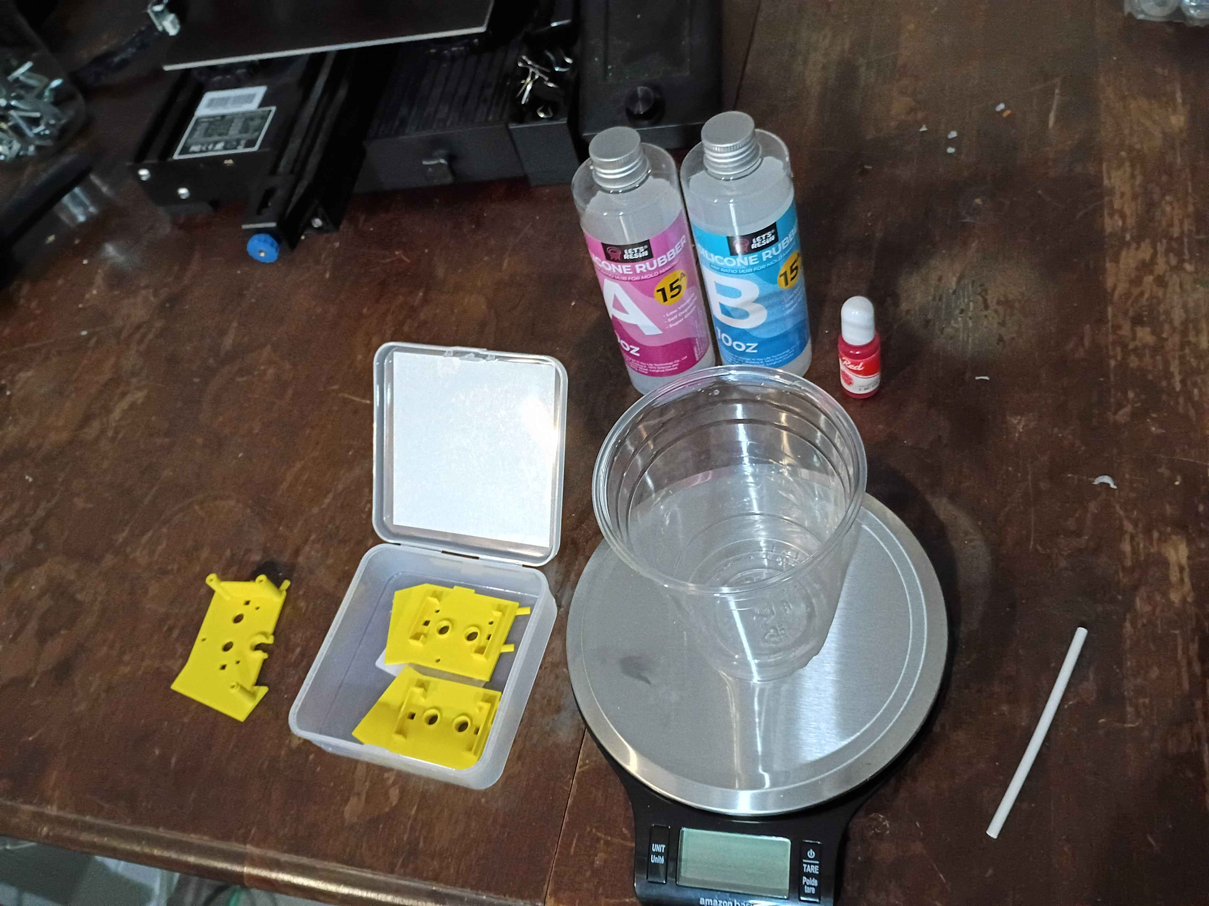
Set up & tested basic camera and Twitch redeem bot basics for livestream interaction. Fixed minor bug with Mary-Bot. 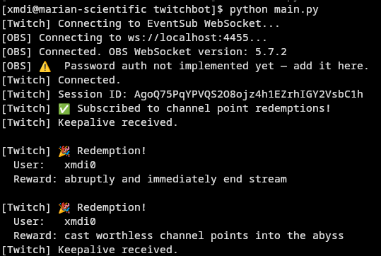
Redistributed all electronics components after recent acquisitions. Also set up a pretty good 3-camera set up for streaming and cleaned the majority of the workshop. 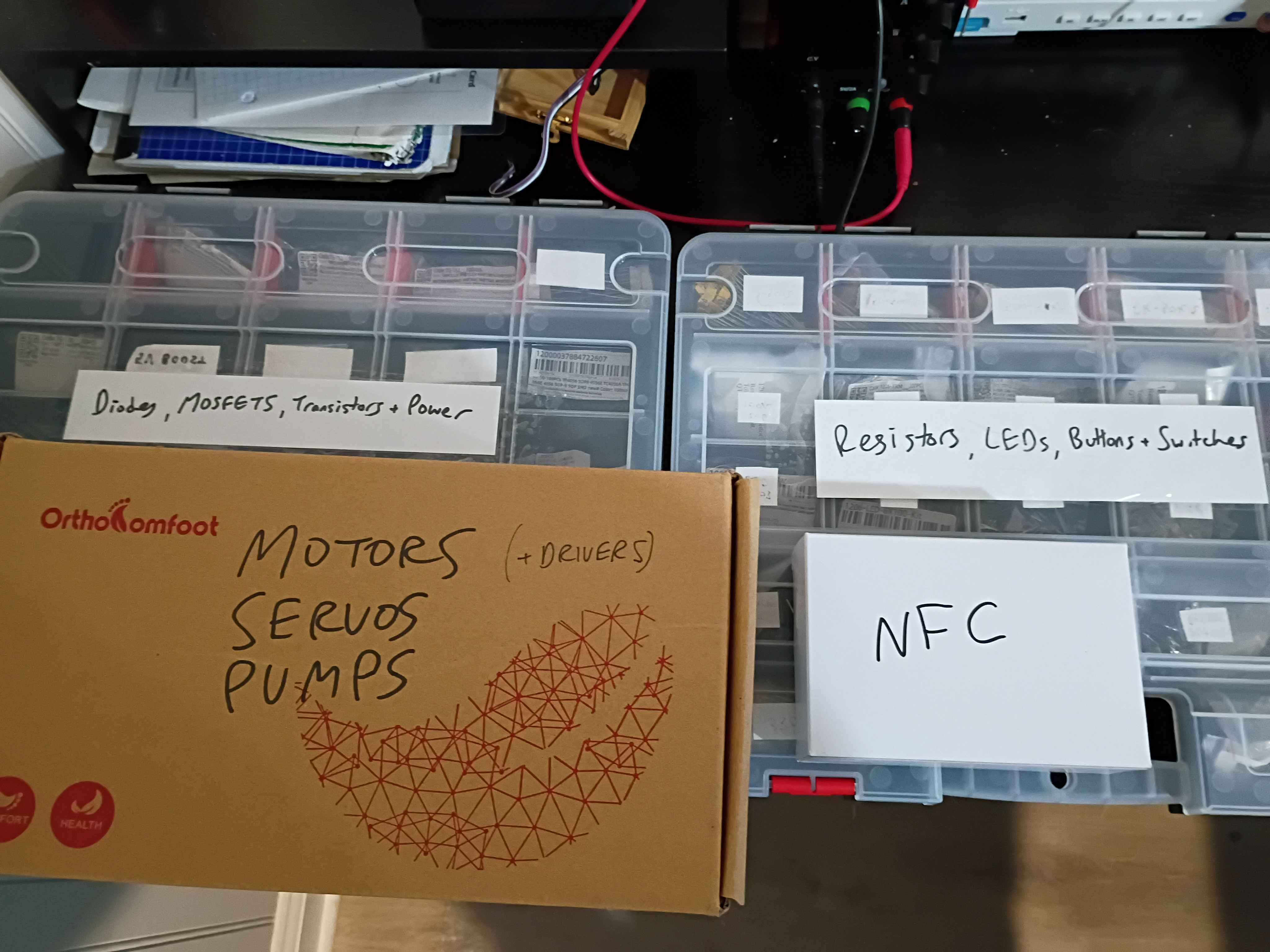
Added depth component to the Pentecost-Pursuits initiative via Mary-Bot.
After a lot of floundering, determined a reasonably effective way of desoldering thru-hole components. Insert the board inverted in a vice and heat them up while pushing the exposed pin down thru the hole. A solder wick is useful to remove the bulk of the solder before attempting to push the leads thru. 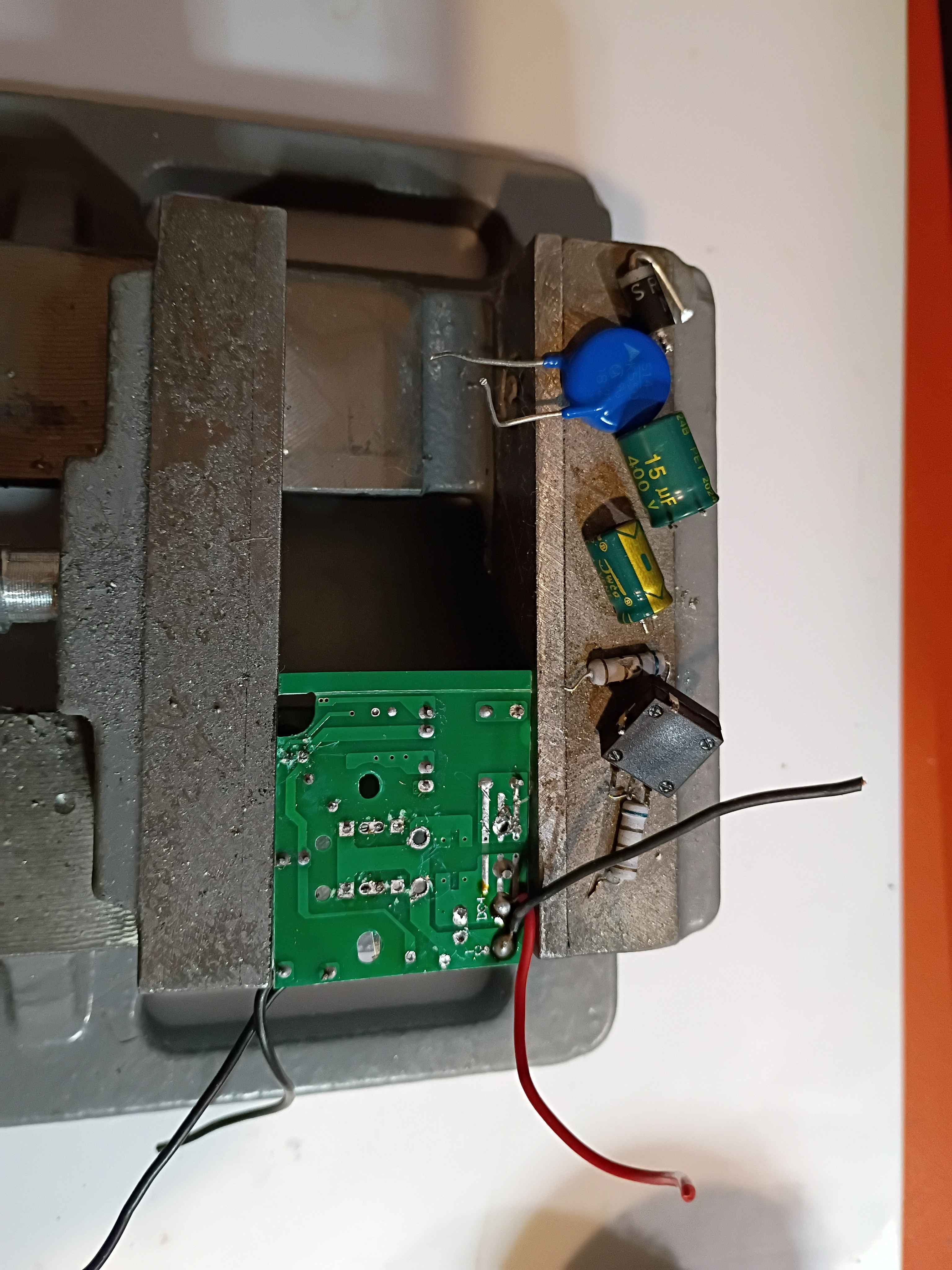
Got bit-banged I2C working on the ch32v003, which was a massive headache, around 800 bytes in the binary. Still way easier than using the built in I2C peripheral. And it allows use of any pins, which is good. Also realized that the WCH LinkE programmer can provide 5V as well as 3.3, which is very good to know. 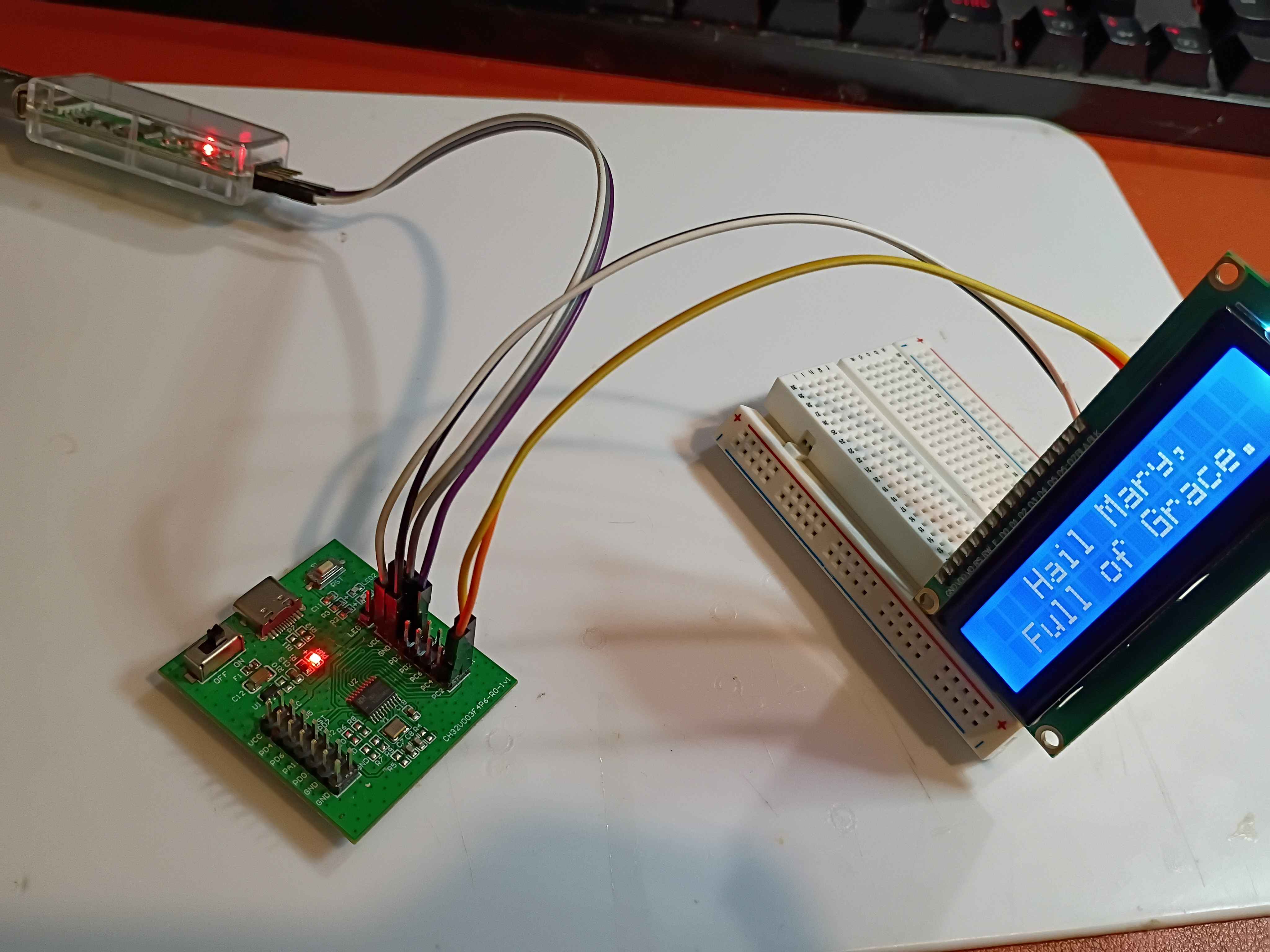
Created the ex04_adc and ex05_pwm ch32v003 template assembly programs. Updated the documentation entry in the microcontroller sandbox.
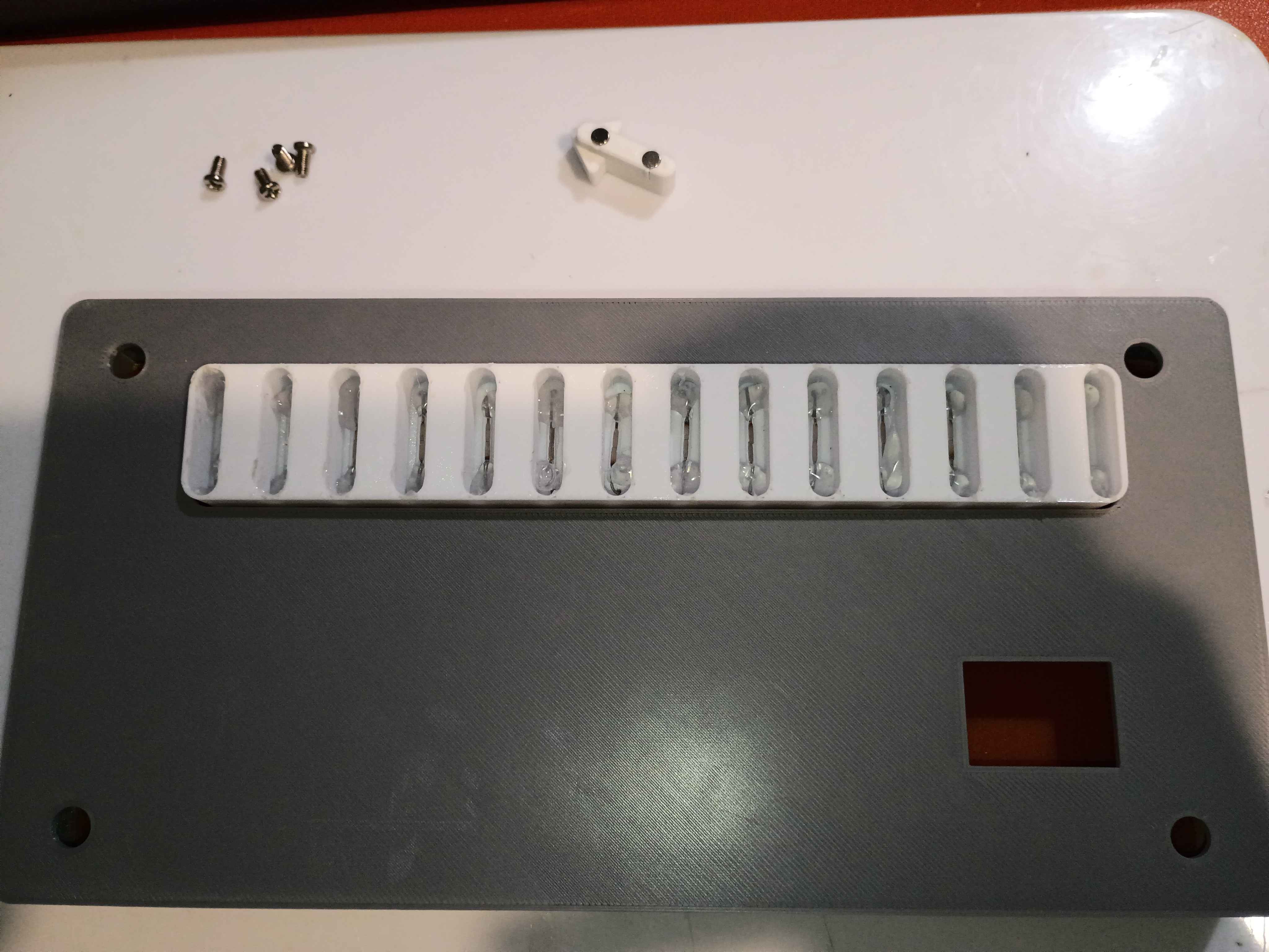
Concepted out Hackaday contest entry, a gravity powered curtain opener/closer. Designed four simple components in 3D that allow weights tied to the center hole of the -005 components to sequentially slide out of a carriage assembly and thereby draw the curtains opened and closed. The -007 slider is connected either to some servo or a bimetallic strip. As it slides inside the -008 channel, at either extreme, it makes an opening for the next -005 sliding component to fall by gravity out of the carriage. A frame will be necessary to hold the -008 and -006 components in relative position, as well as the motion input system. 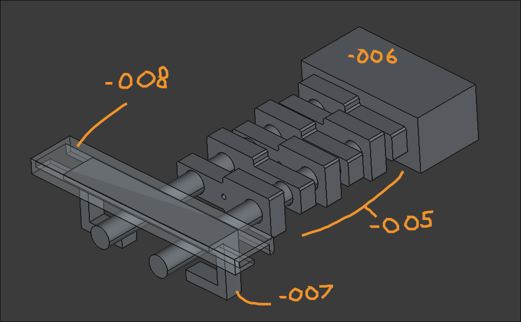
Created barebones documentation entry in project repository.
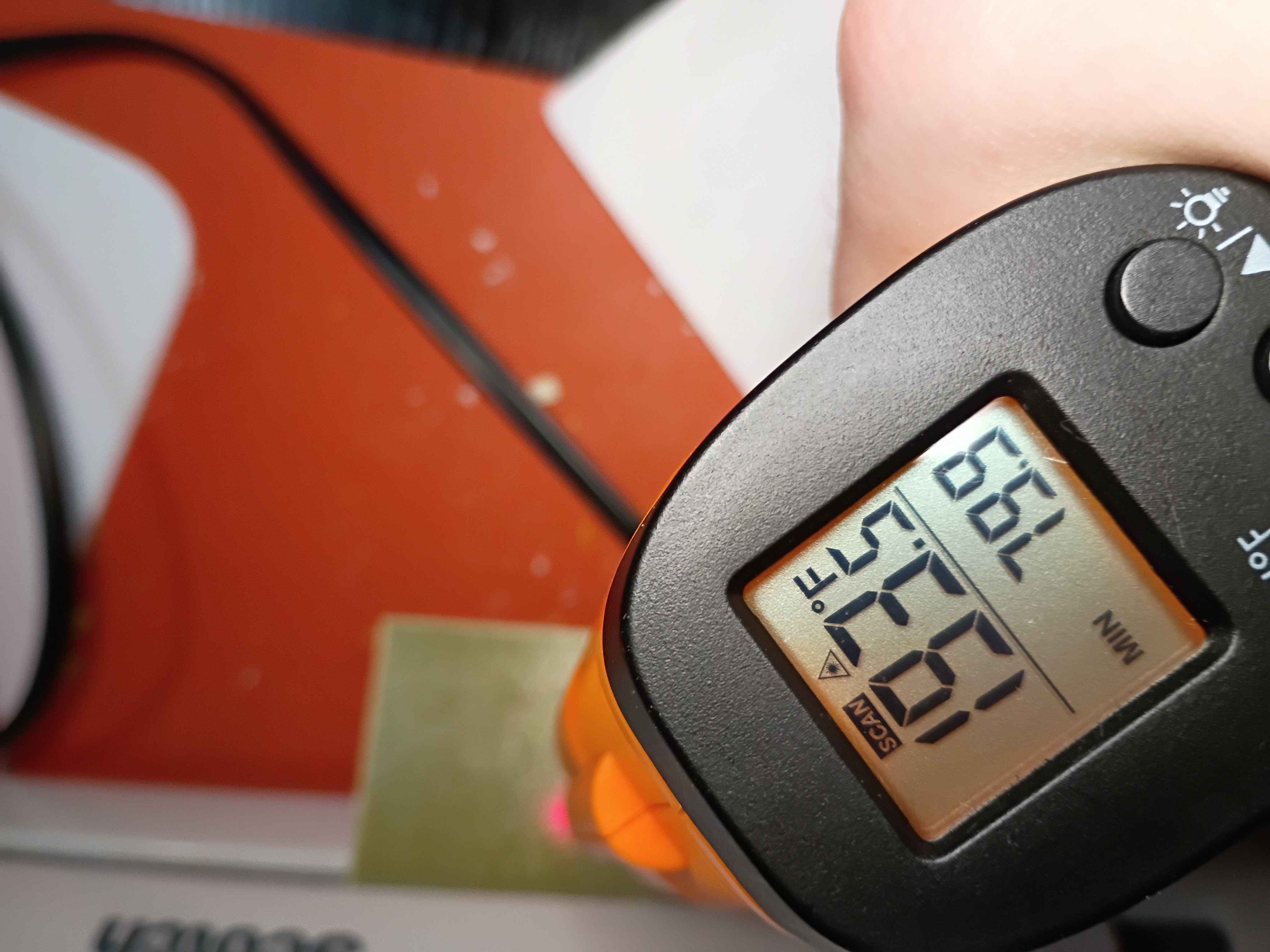
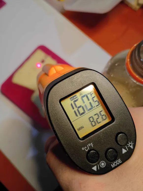
Only burned myself 15 times while soldering and assembling the final modified TL902. It does seem to work pretty well. It manages to get over 220F and the potentiometer enables you to select a different max temperature. I used polyamide tape to secure everything in place on the inside. However the side brackets are beginning to melt at those higher temperatures, so attempts will be made to cast from a high temp polyurethane resin instead. See video. 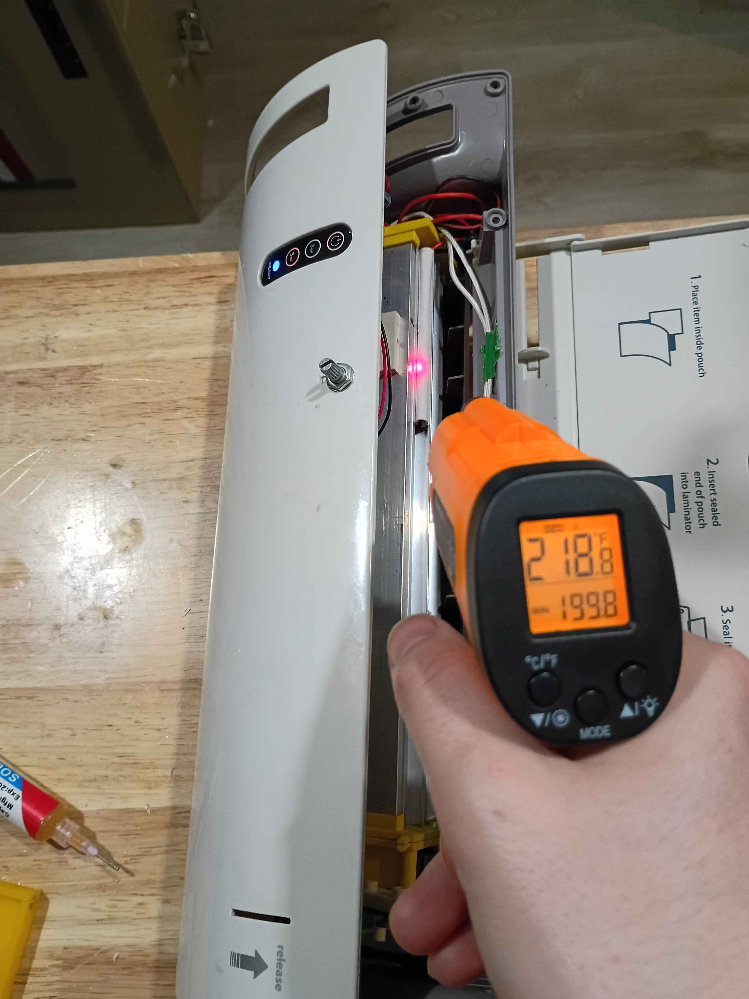
Drew, etched, and soldered the electrical modification board for the thermistor resistance. Was able to do it in less than 30 minutes while streaming, which is pretty quick. 
Abstracted out specific addresses and values to a definition file for the ch32v003 assembly code. Adapted the ex02 blink program and created an ex03 for SDI (serial debug interface) data printing to a connected computer console. Updated the documentation entry in the microcontroller sandbox.
Finished reading (175 pages) the non-project section of The Home Machinist's Handbook by Doug Briney. A very good introduction to machine work using Sherline tools. 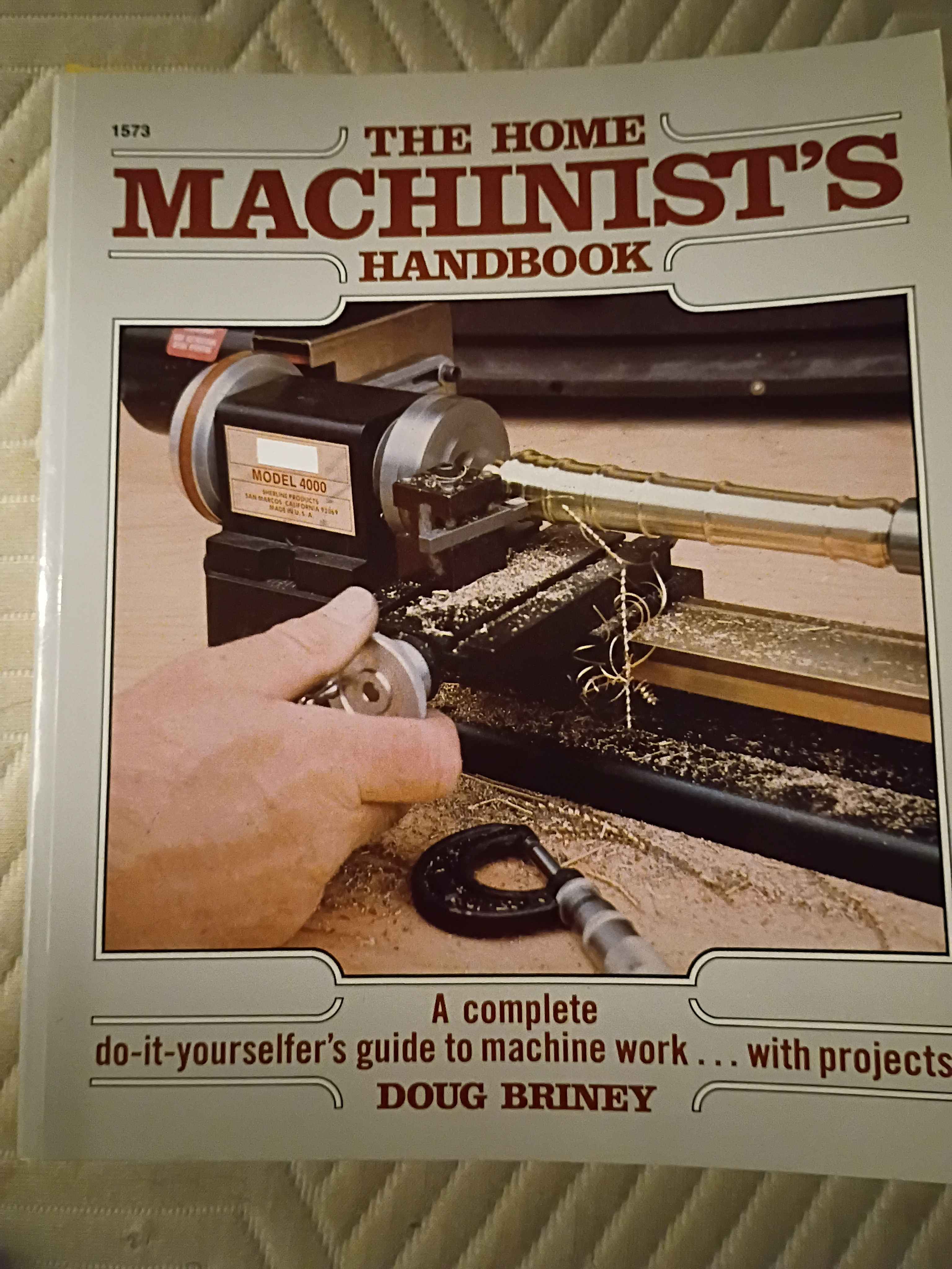
Got ch32v003 dev board to run an assembly code version of blink without the ch32v003fun bloat. Very easy and way more clear in my opinion. Created the documentation entry in the microcontroller sandbox.
Got ch32v003 dev board to run slightly modified sample blink routine using ch32v003fun libs. Was trying to do it with less bloat but was unsuccessful. Will try again later. 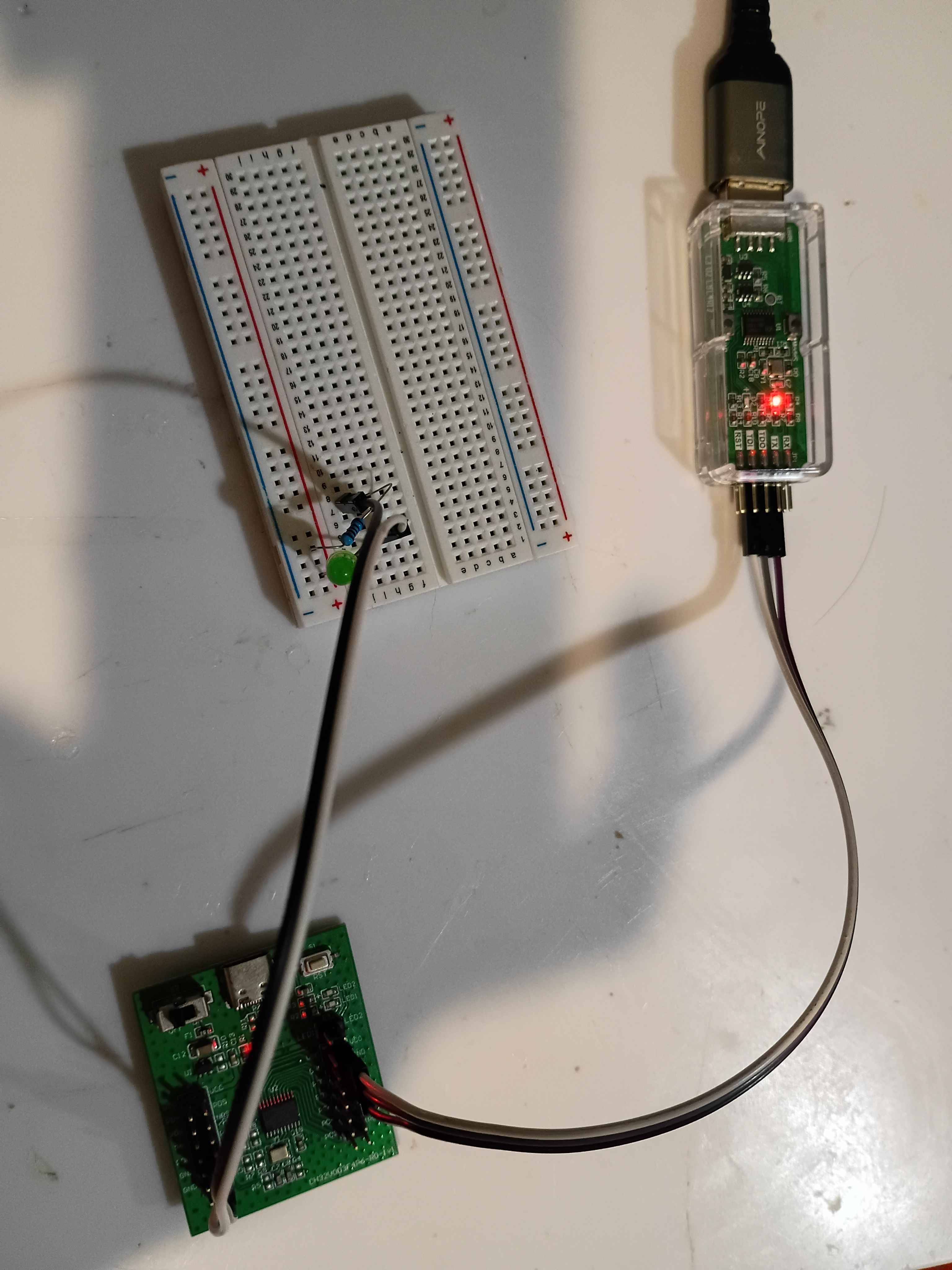
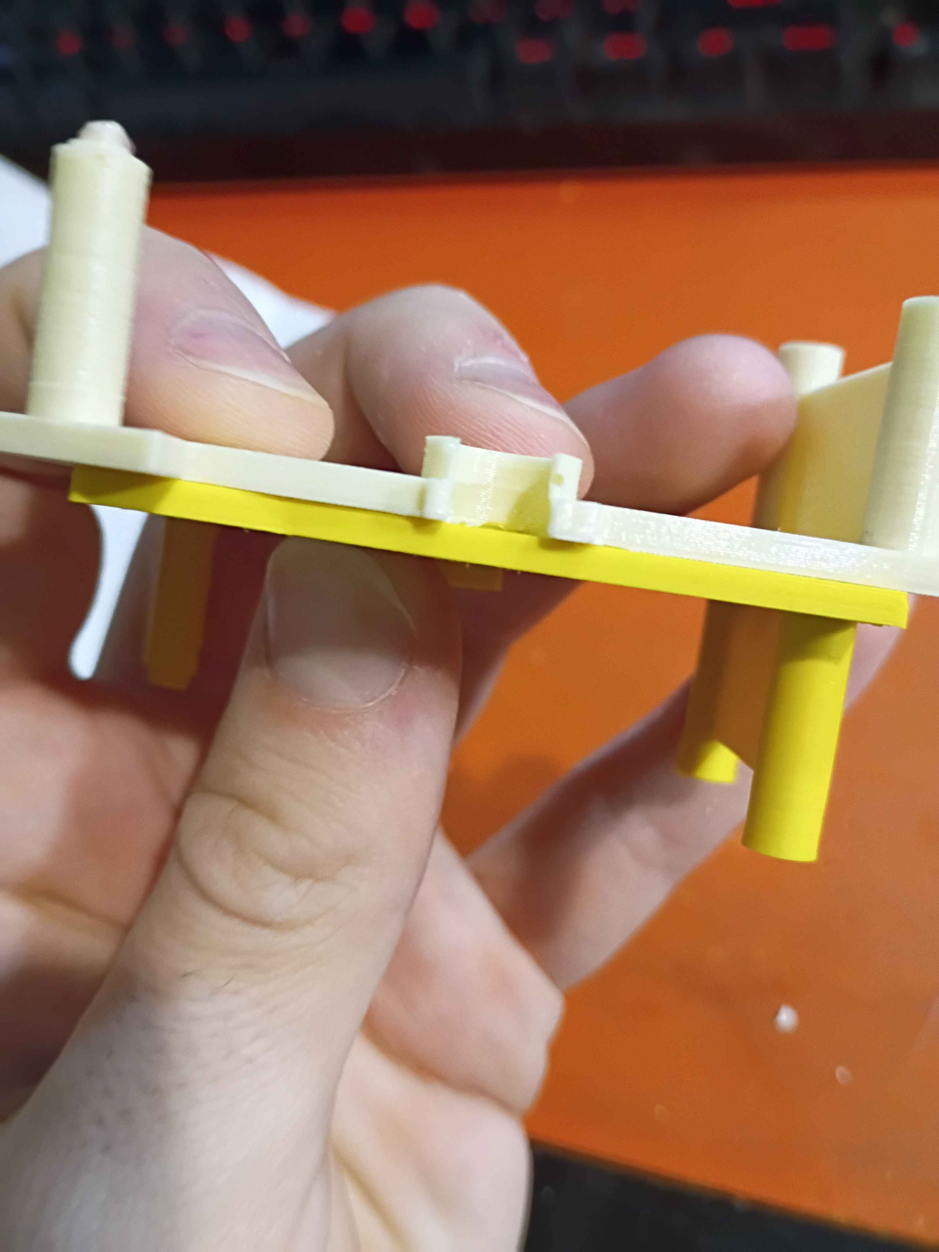
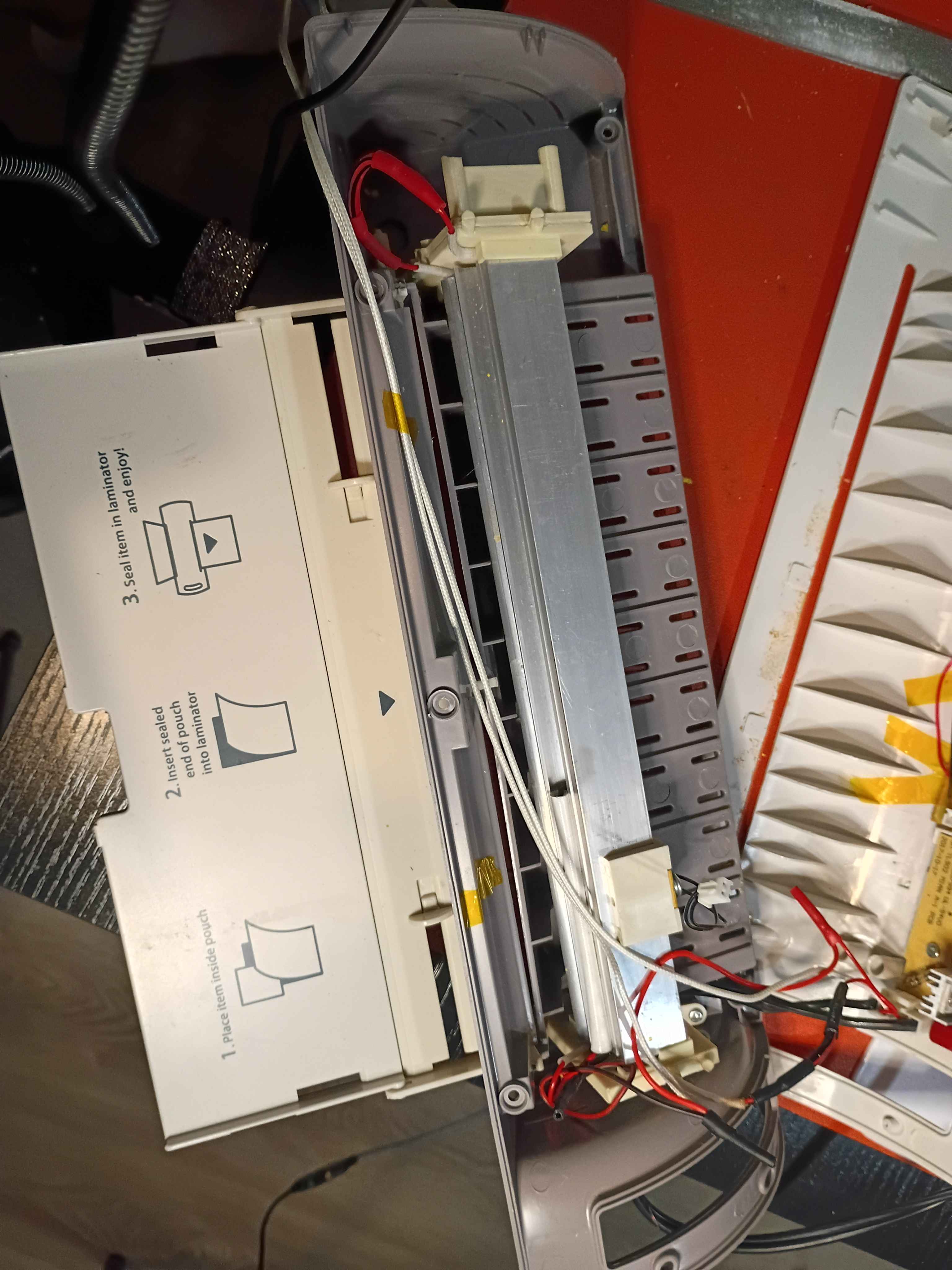
Rebuilt the laminator using the new side brackets and, although they were not perfect (in reality the lower pin on the motor side bracket needs to be adjusted slightly, though it works as is), and resoldered all the connections after threading the wires through the printed pieces. The motion system works perfectly as intended. See video of it in action. 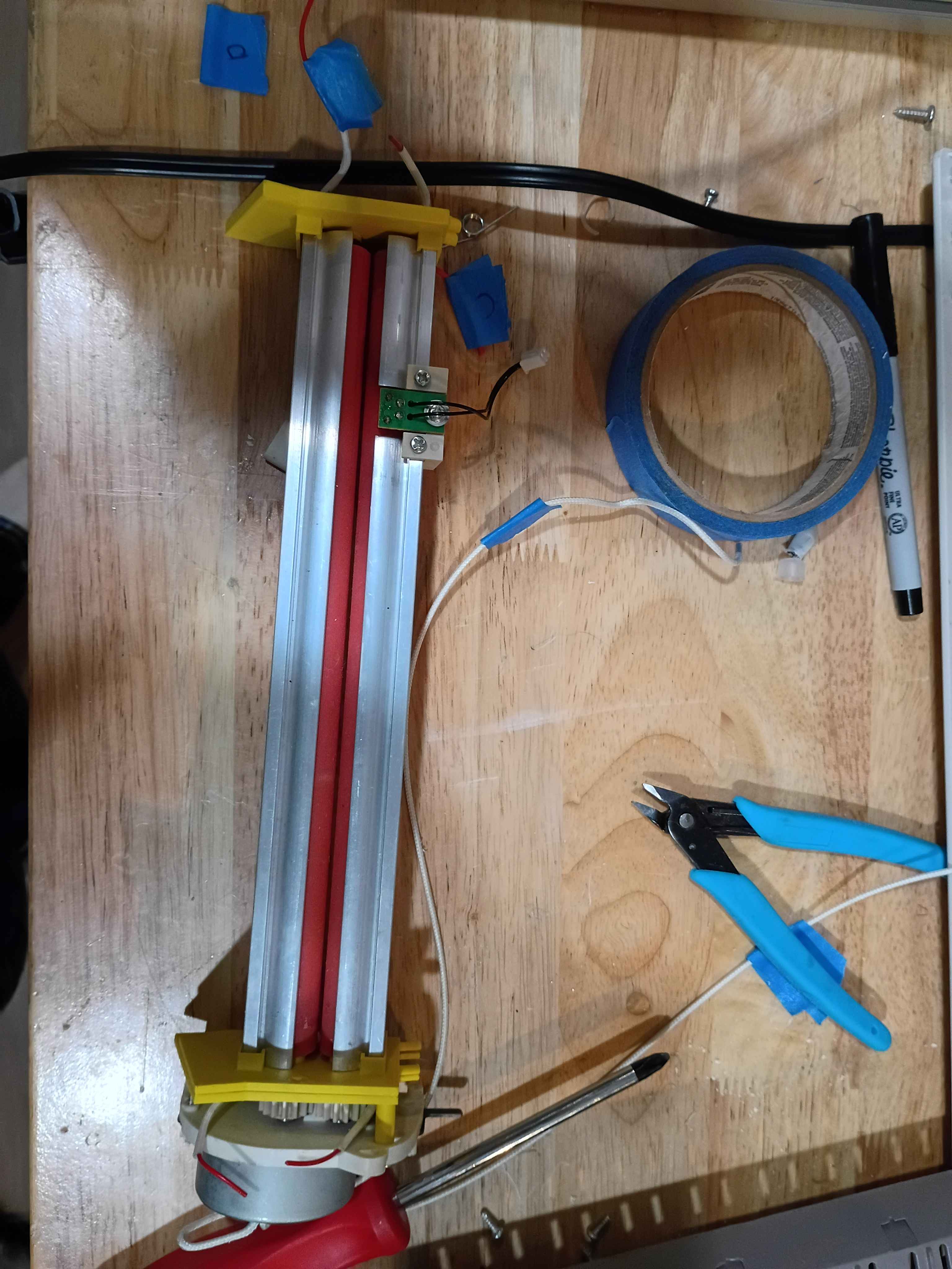
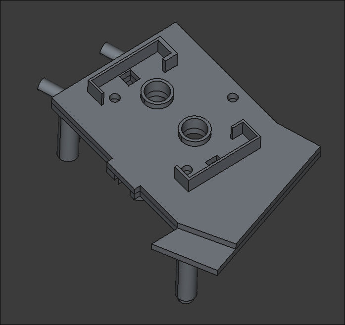
Updated design for left-hand bracket per fitment test of previous iteration. Prints should complete overnight. There is no need to actually bond these two together, as they will be clamped together in the assembly. Likely won't need to print/source new gears, as the existing ones seem to mesh fine with the greater separation distance. 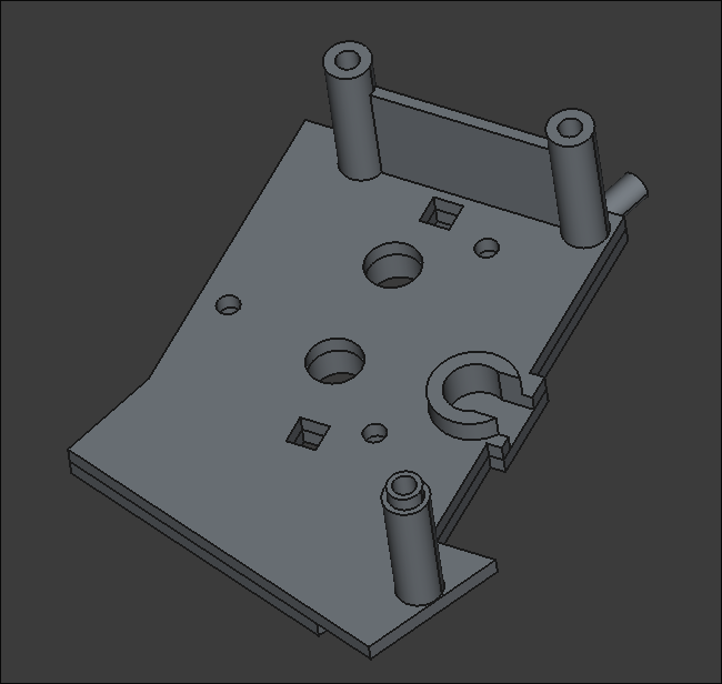
Updated mary-bot to automatically report pentecost-pursuit progress on a daily basis at midnight.
Incorporated design iterations in 43001-002 and divided into an upper/lower half to facilitate printing. 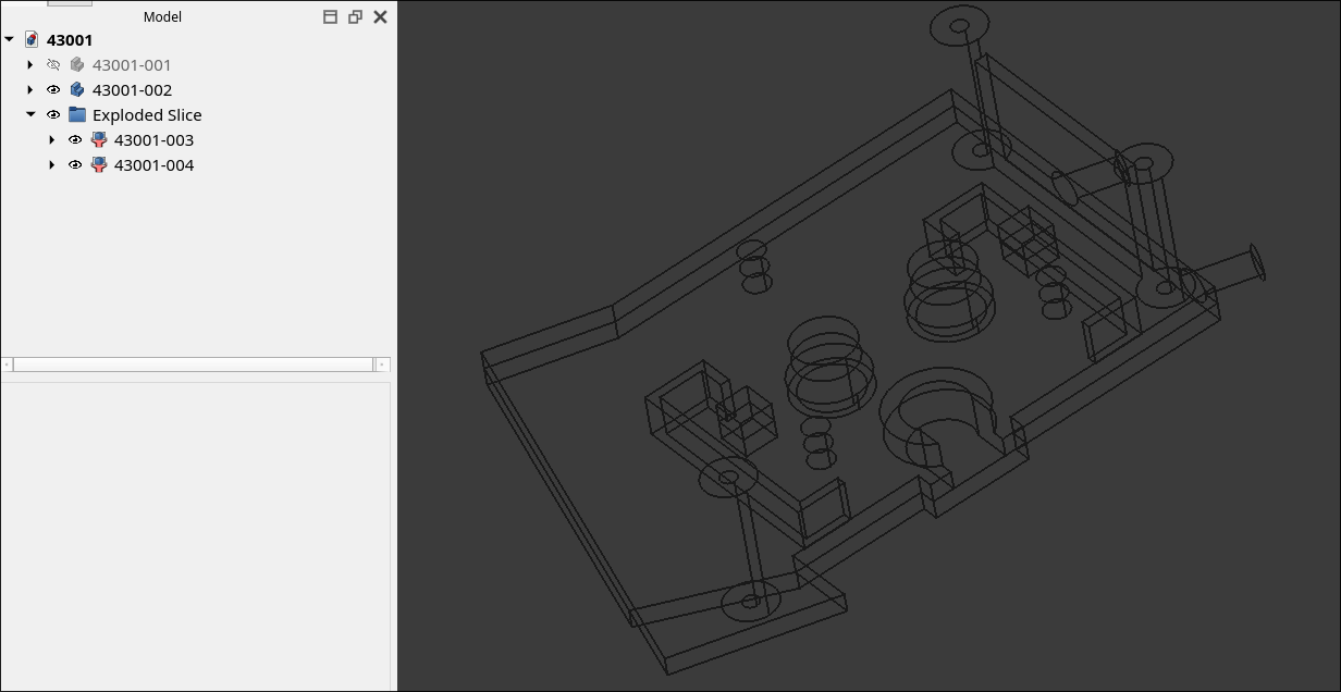
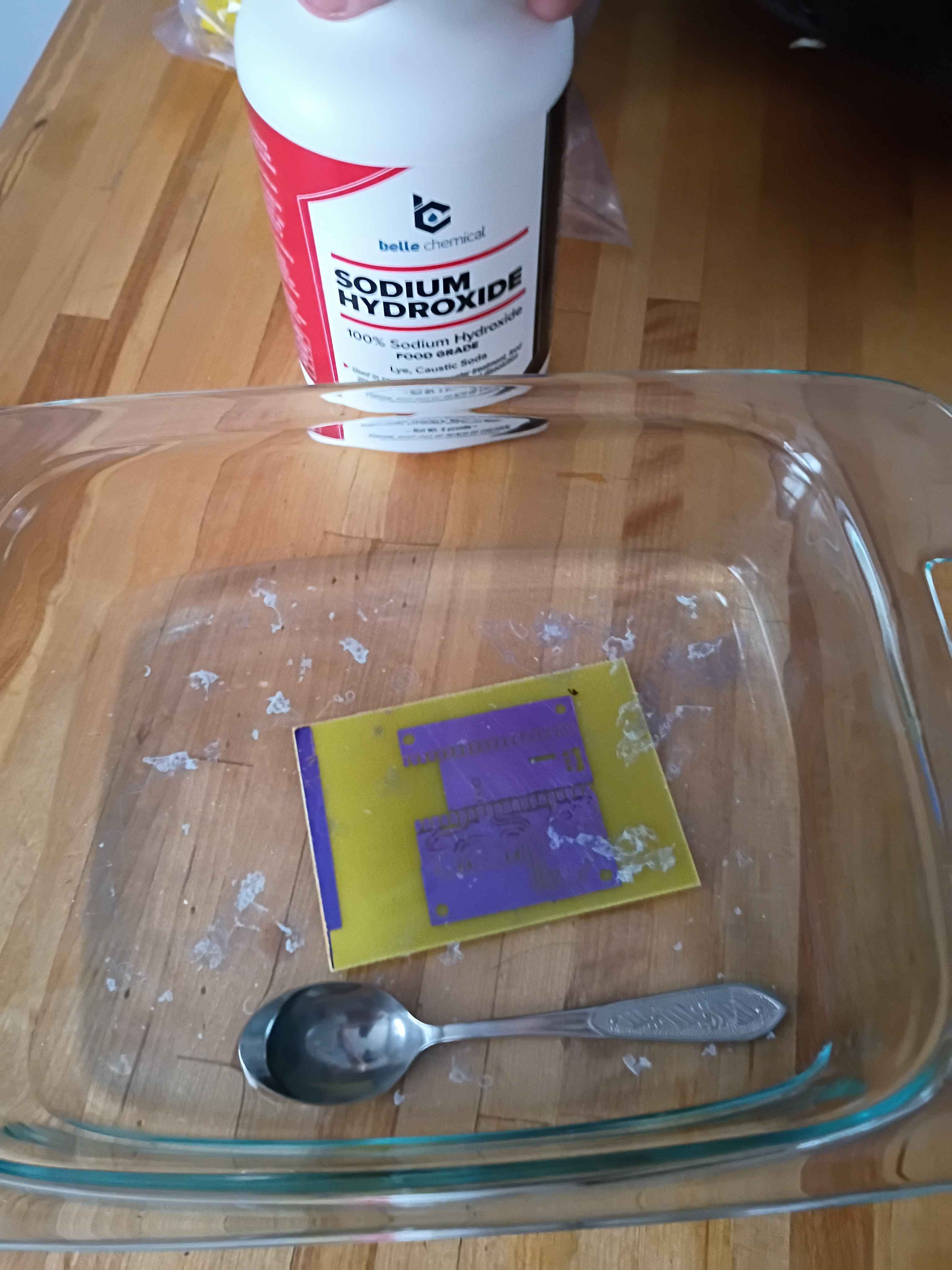
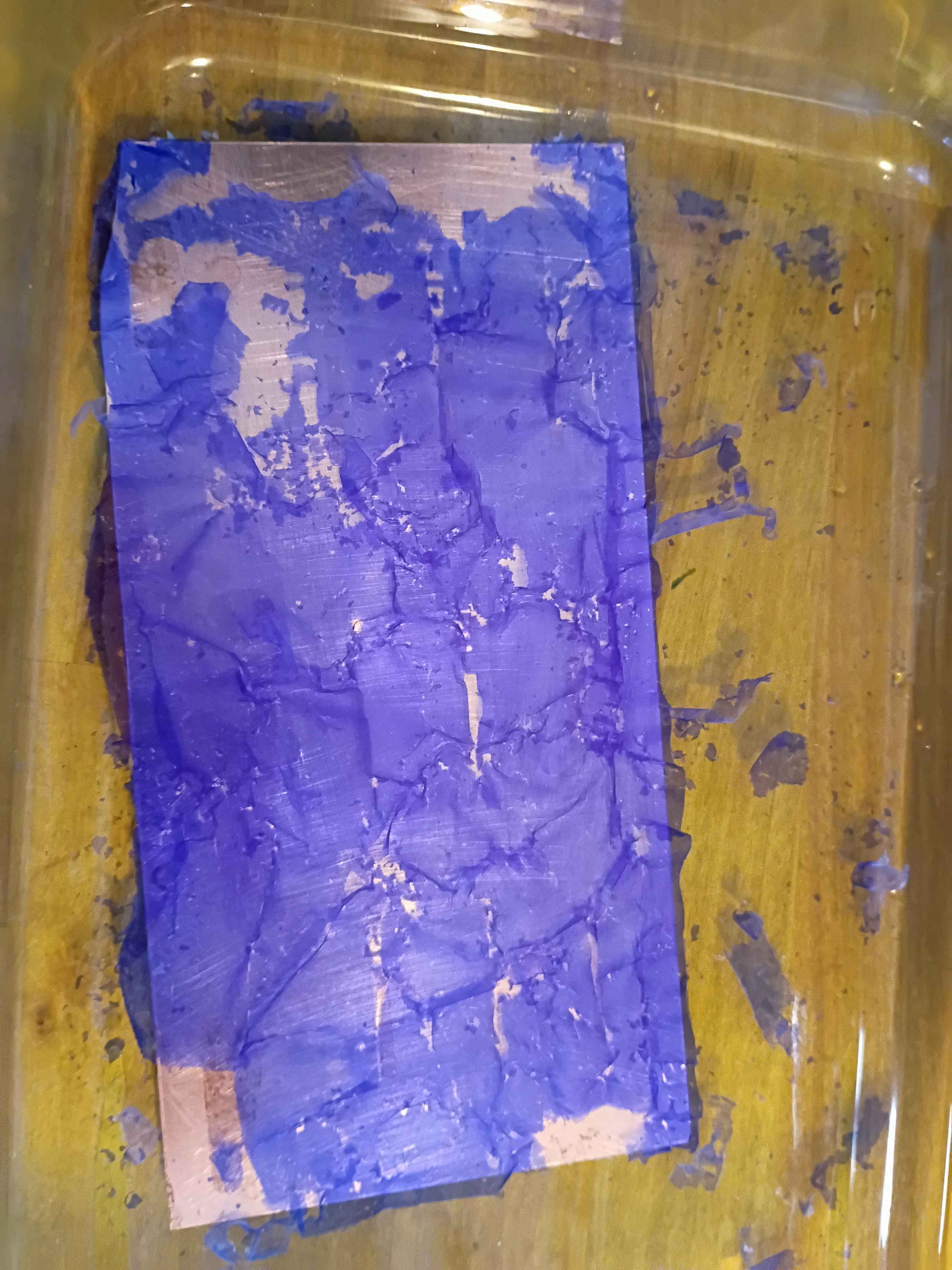
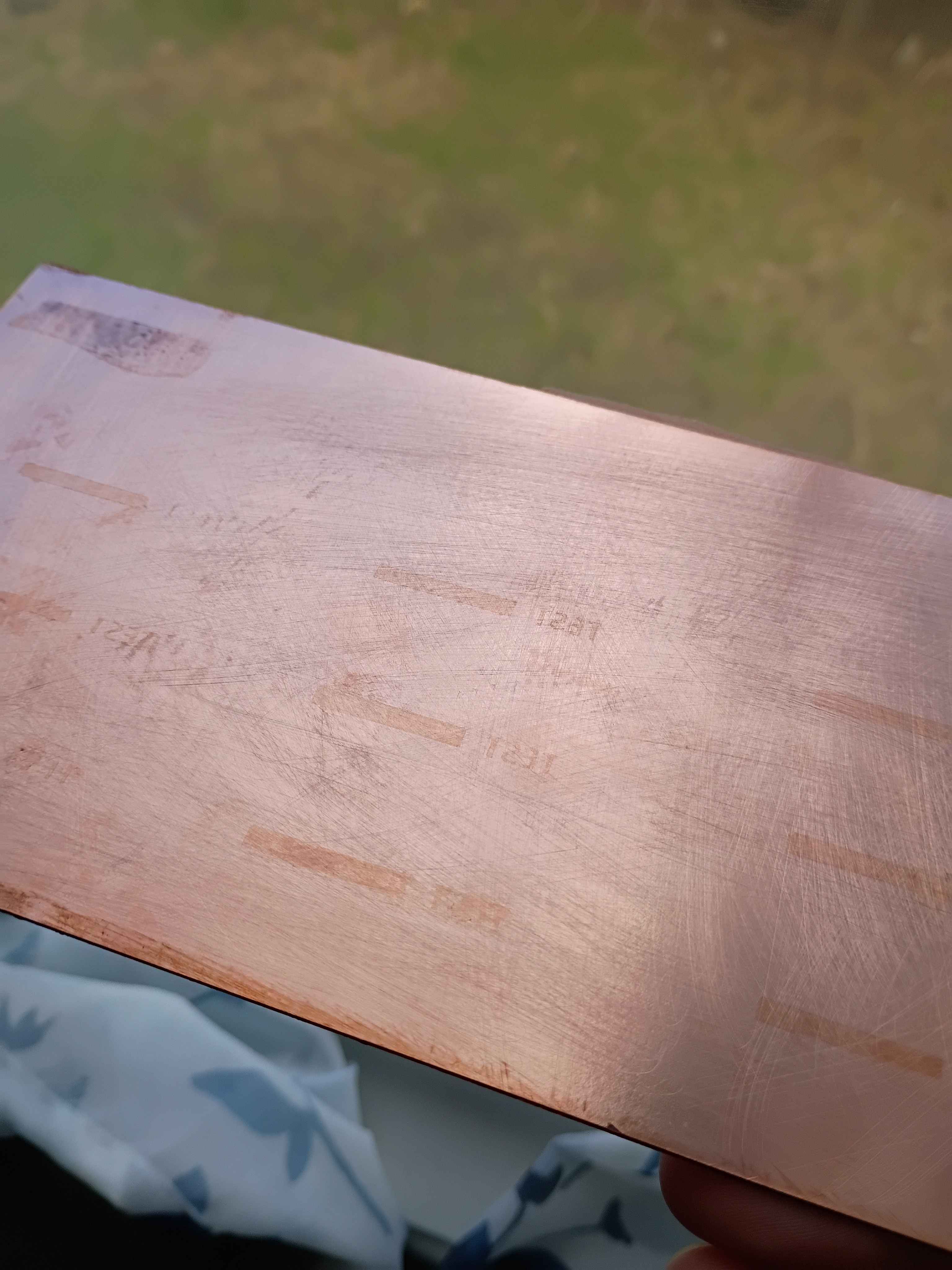
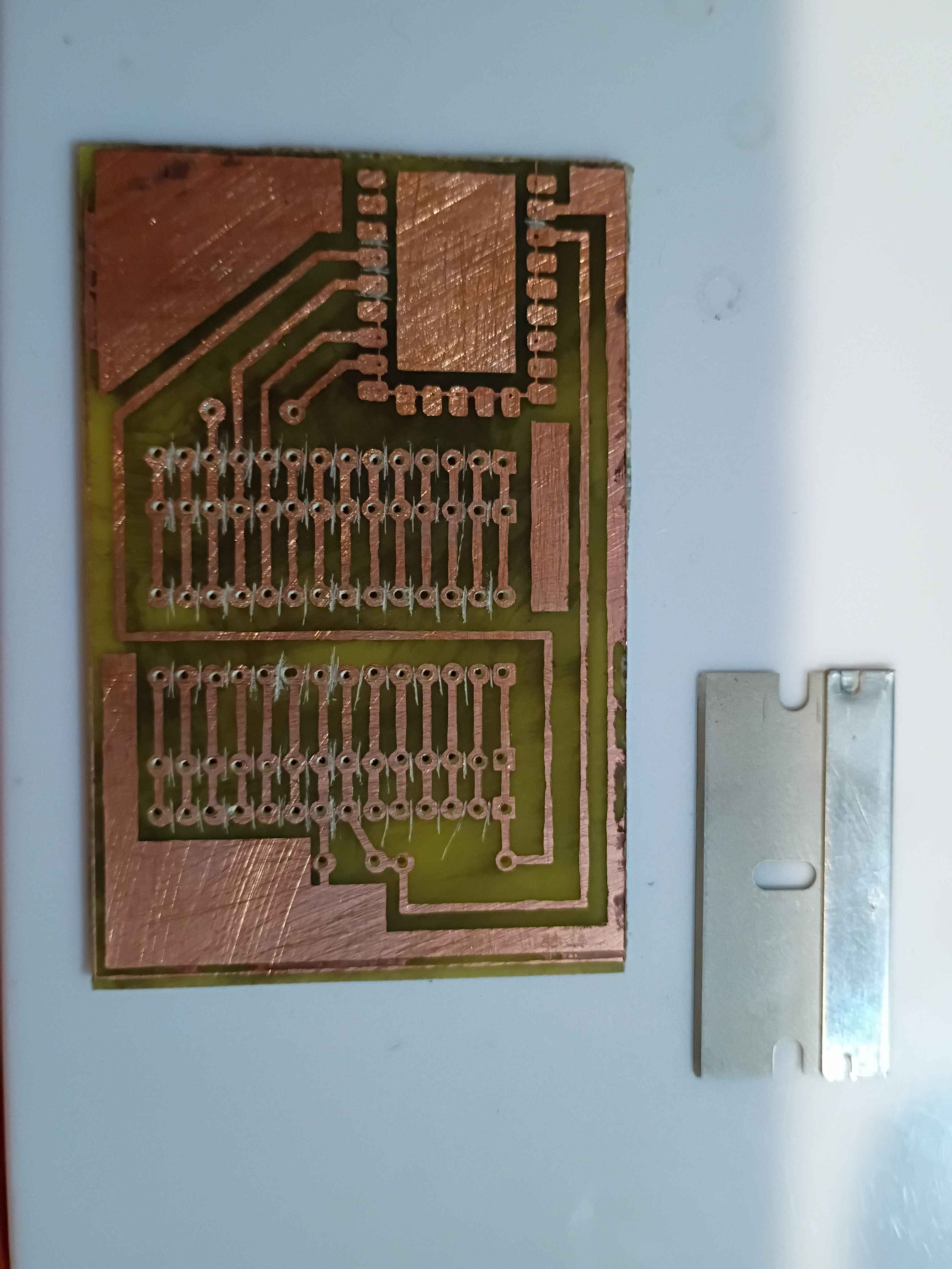
Added 2 tsp of sodium hydroxide to 500 mL of water to dissolve off the hardened photoresist on the test panel. It only took a few minutes. The only remnant was the oxidation that built on the exposed areas. 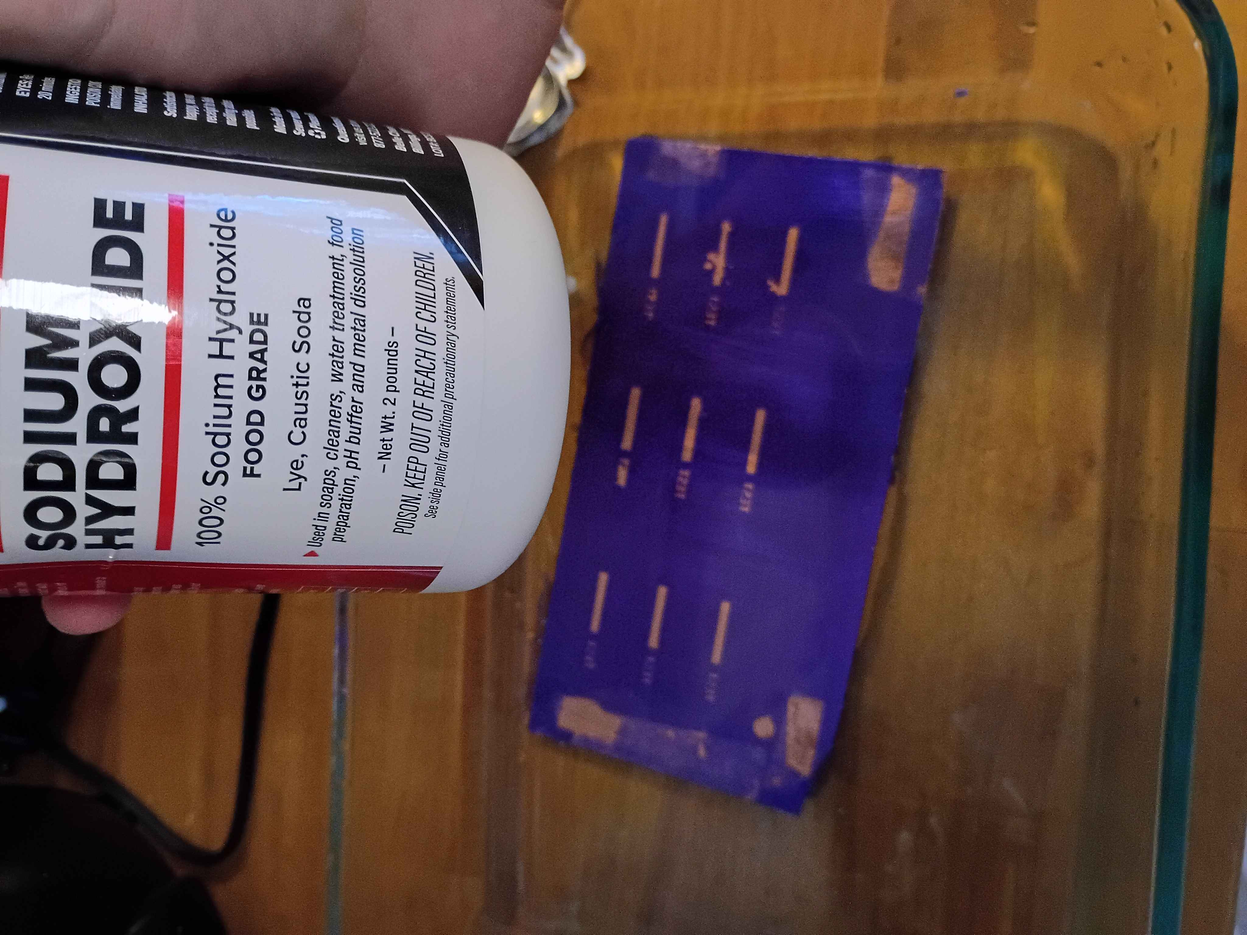
"Fixed" the printer problem from last night by leaving the lid open. The right-hand bracket does seem to fit all the components perfectly, though the top pegs can be thickened, though they currently match the original part. Designed and printed left-hand bracket piece, without stepper motor standoffs. 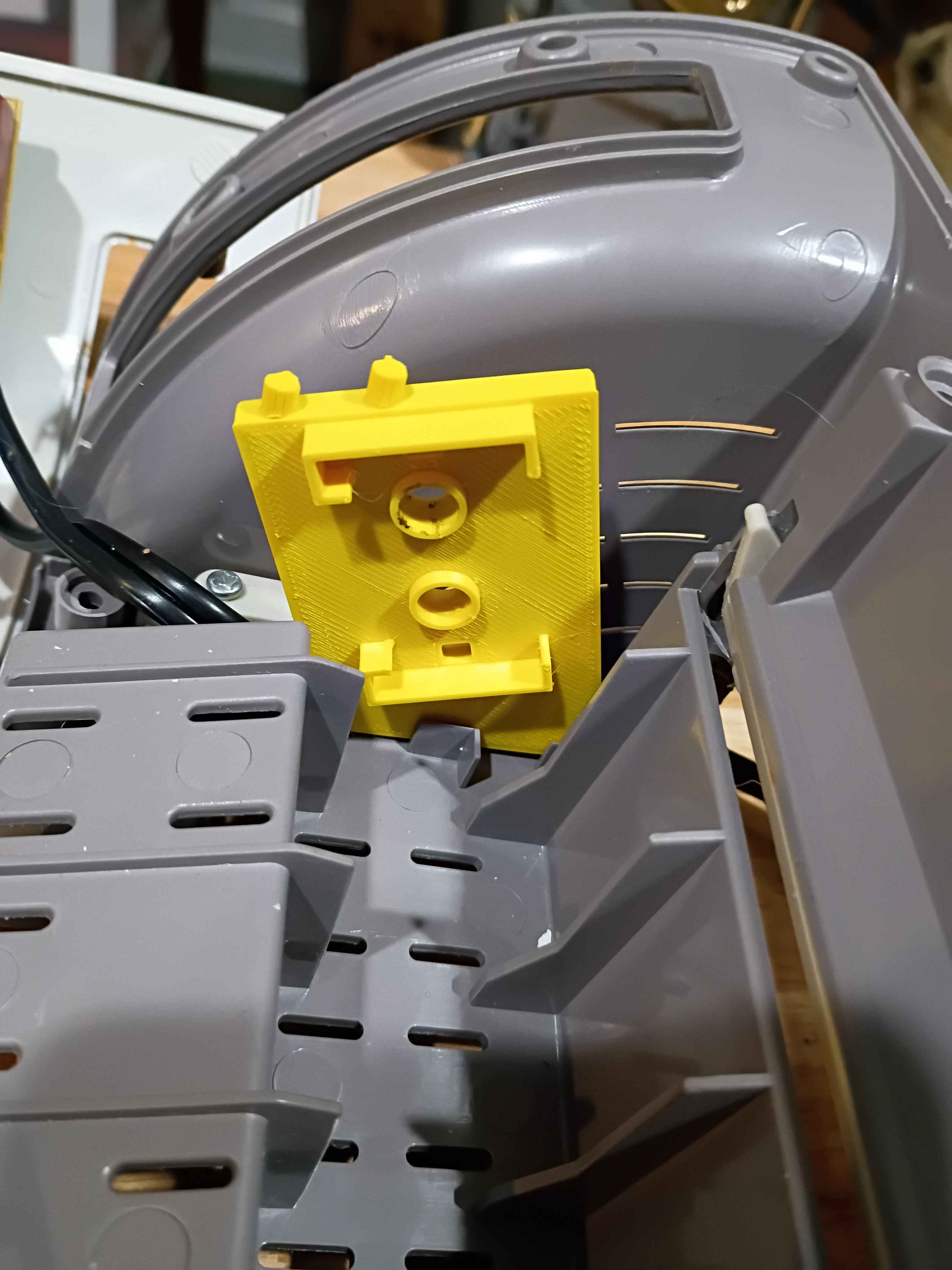
Revised right-hand roller support bracket to improve fitment and modeled left-hand bracket. Left-hand bracket needs mounting holes as well as standoffs to mate with the motor bracket. Had printer issues related to the thermistor while trying to print. I think it's some connectivity problem and am working to fix. 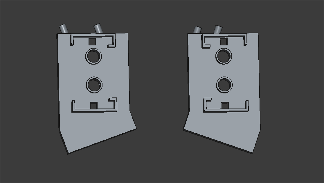
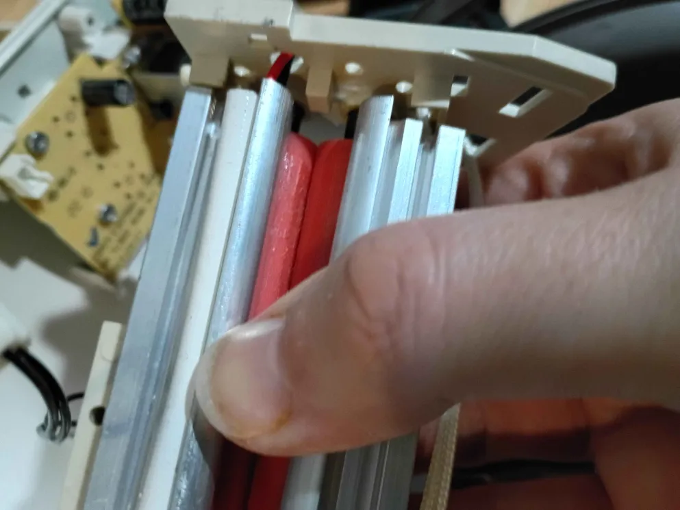
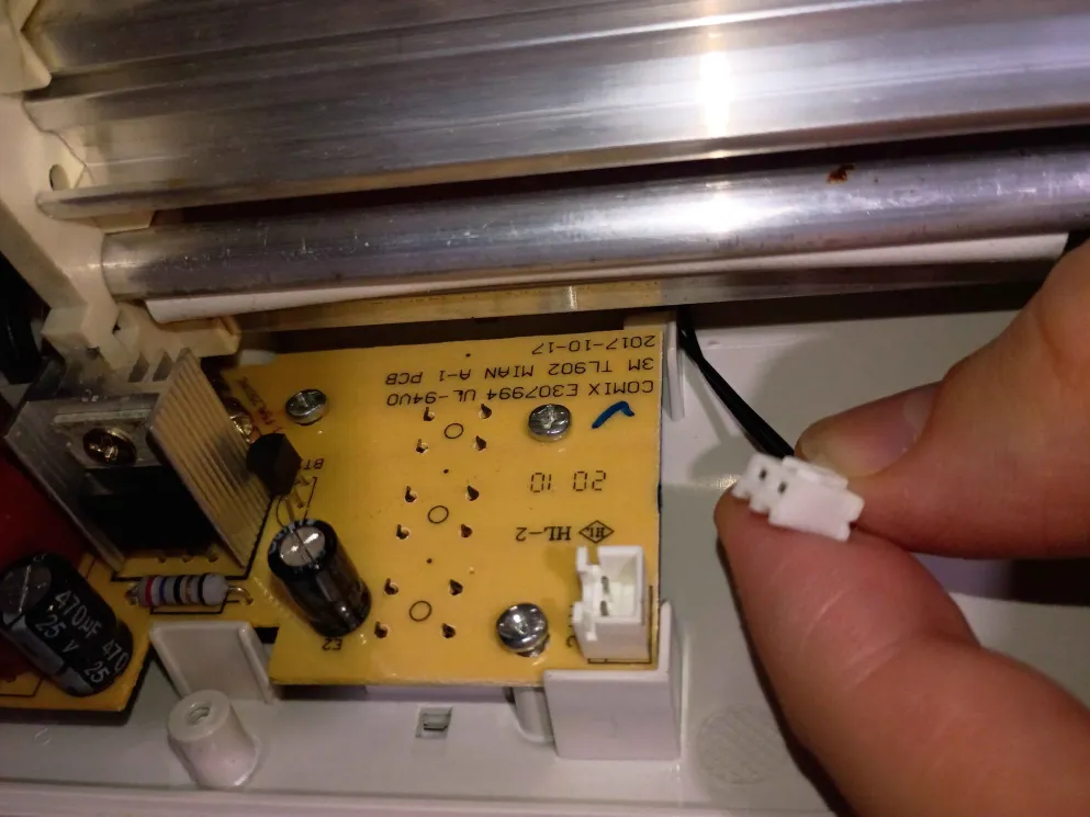
Began teardown of TL902 thermal laminator for thickness mod and temperature mod. Located potentiometer and JST connector for temperature mod, and began redesign and print of one side of the internal bracket that spaces the rollers apart. 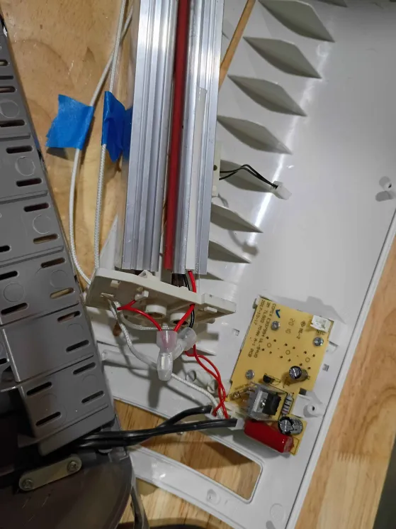
Finished automated graphic rendering for the pentecost-pursuits status and implemented the submission process, requiring a journal entry. Type !help in that channel to see a description of the commands. 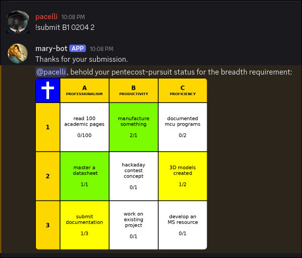
Added functionality to Mary-Bot to not require IMG tags in journal submissions, fix a bug regarding the termination-notice filetype, and did some preliminary work on the pentecost-pursuit graphical rendering backend. 
Did manage to get a toolchain working for the plotter using jscut.org. Originally I attempted to use InkScape's built-in Gcode plugin but was unable to operate on the circuit mask because there were too many paths. Eventually I figured out that you can ungroup, flatten and then reconstitute all of the features into a single path, though the order to do that requires some stumbling around. By that point, I was using jscut, an outdated browser utility, which worked decently enough. The main problem was that because I didn't have the proper hardware to assemble the plotter head, the Ultra Fine Point Sharpie was rigidly mounted to the toolhead, making it blunt rather quickly, which caused both attempts at tracing the circuit to be unusable. At some point I will retry this with a different mechanical setup because the difficult part, getting the software to work, is behind me. 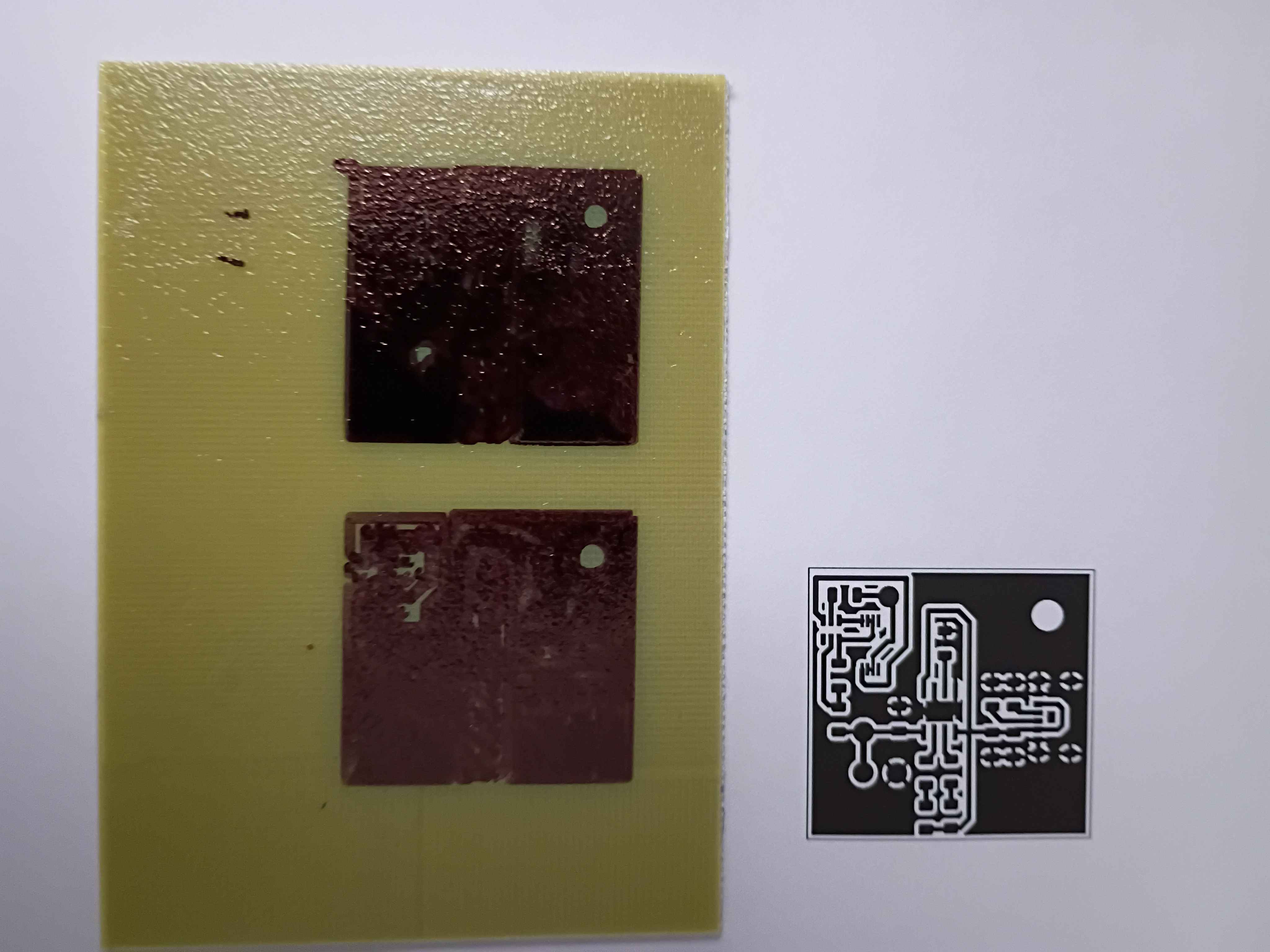
Added a basic employee tracking backend to Mary-Bot, also enabling her to terminate employees and issue a formal termination letter PDF with key details. This will eventually be extended further.
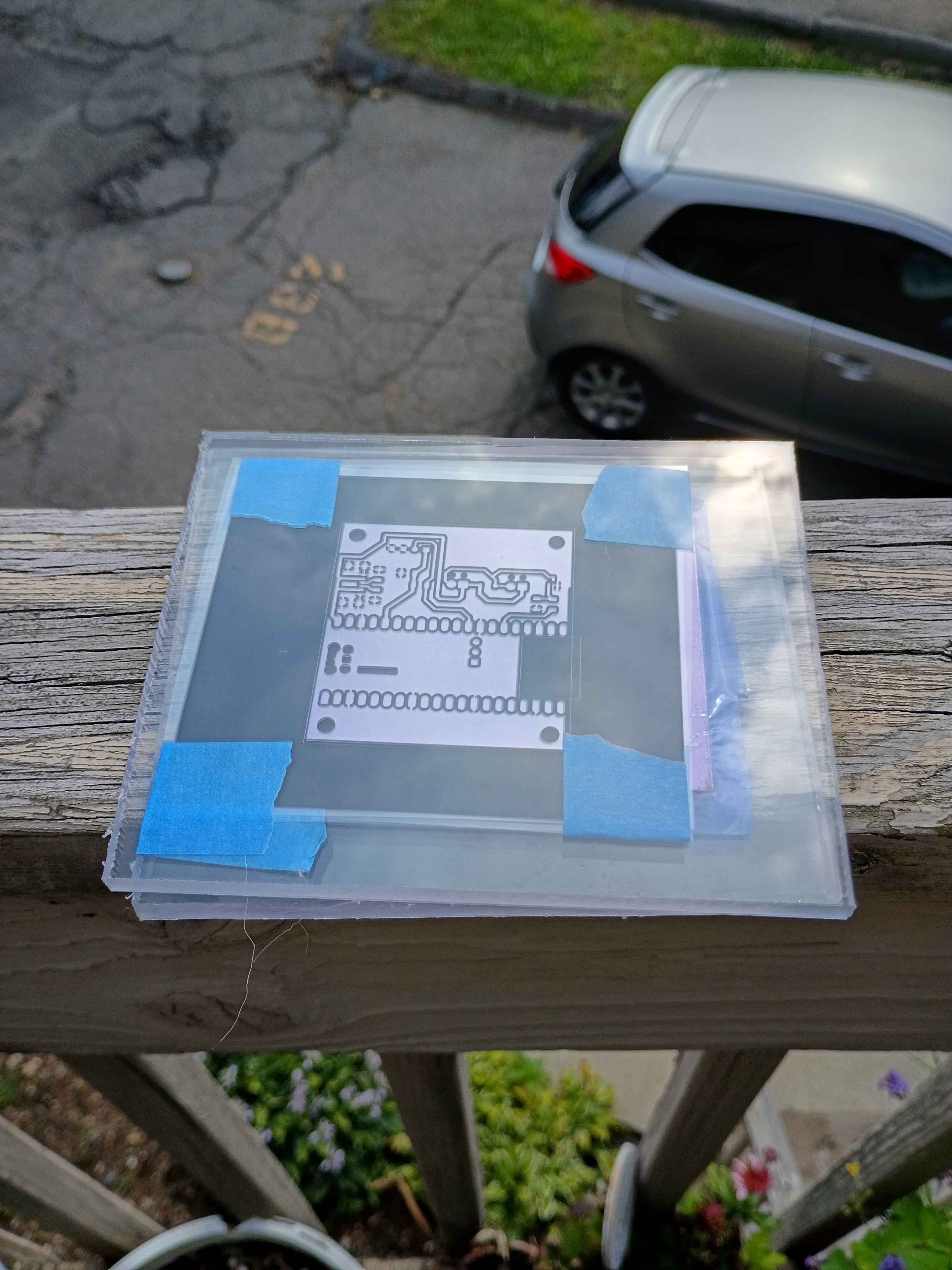
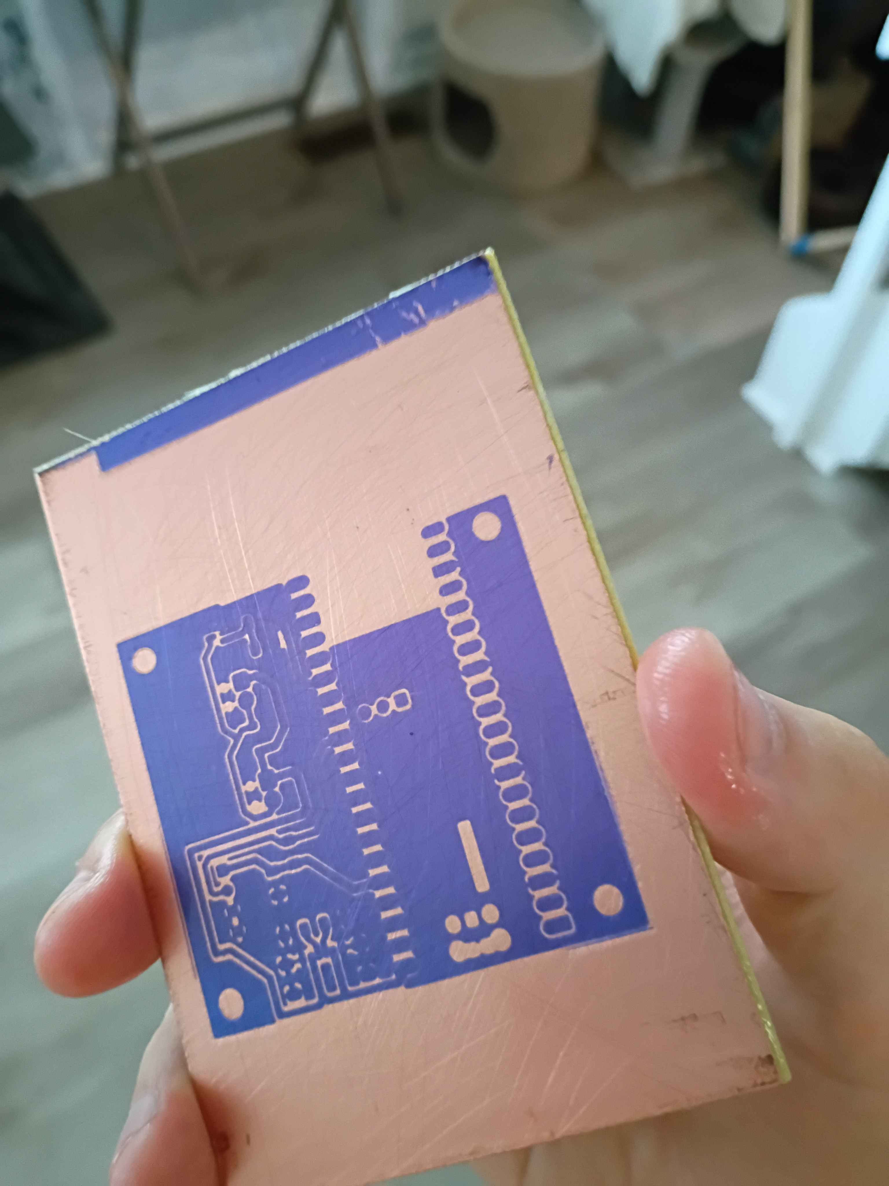
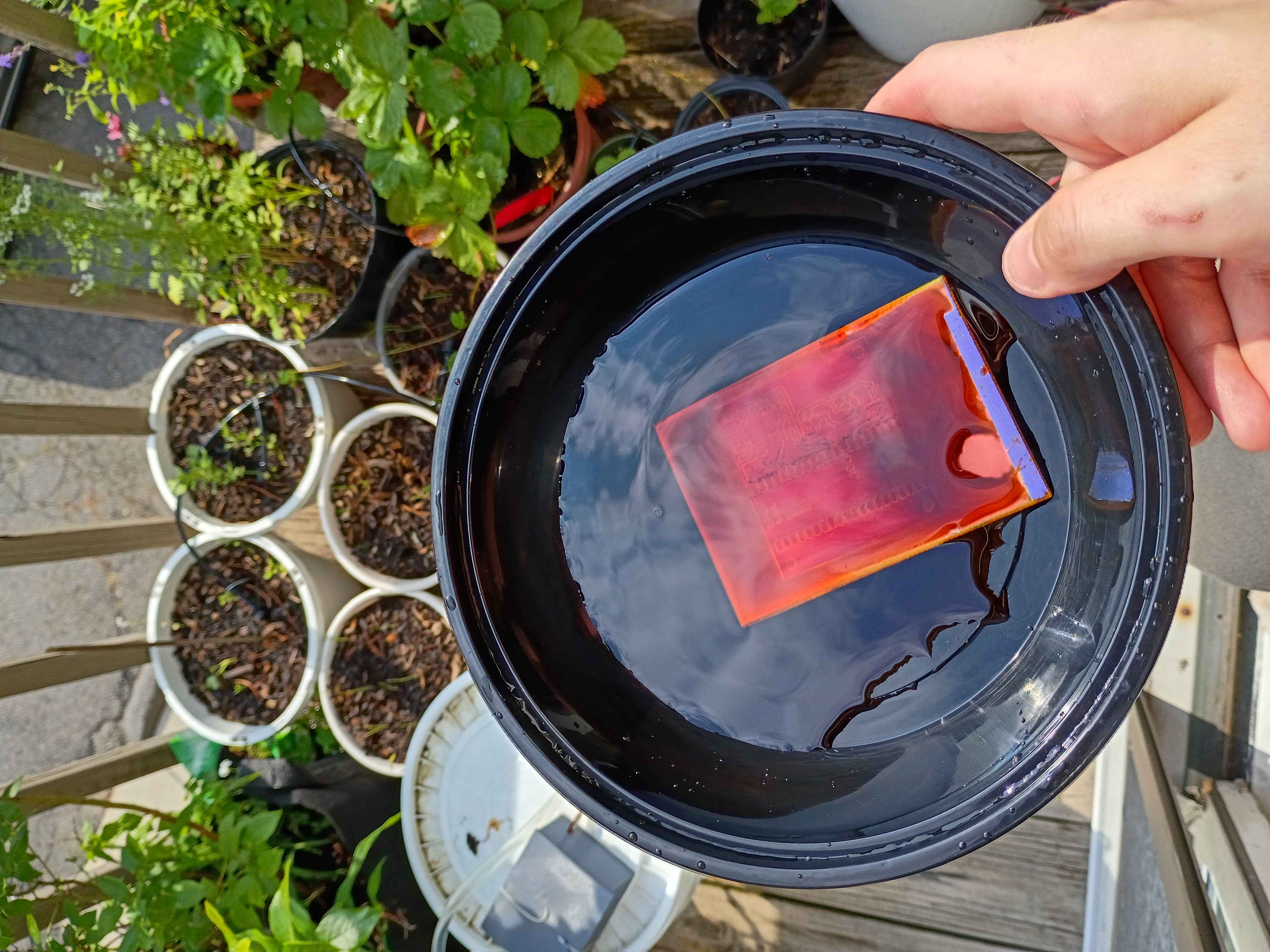
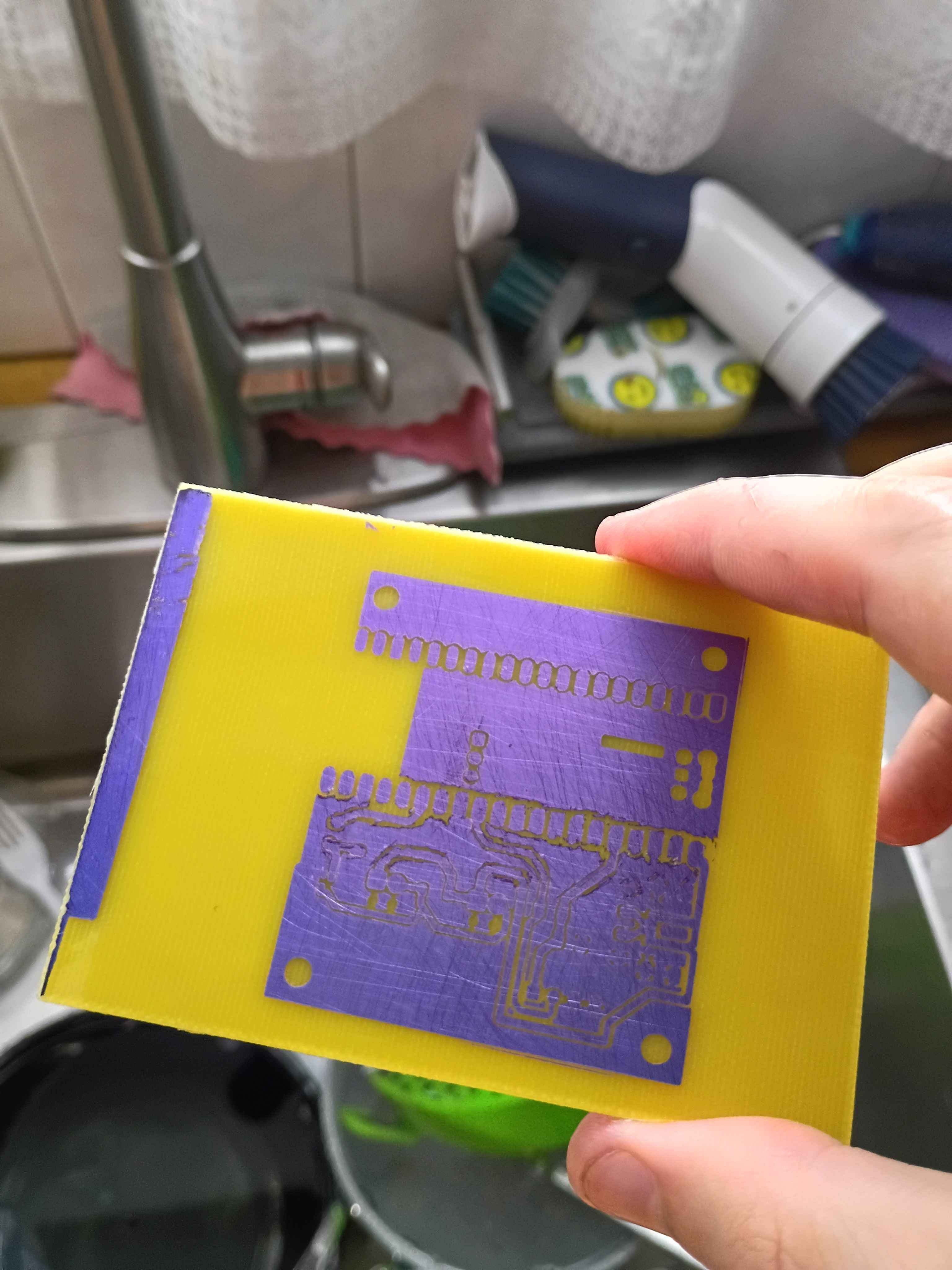
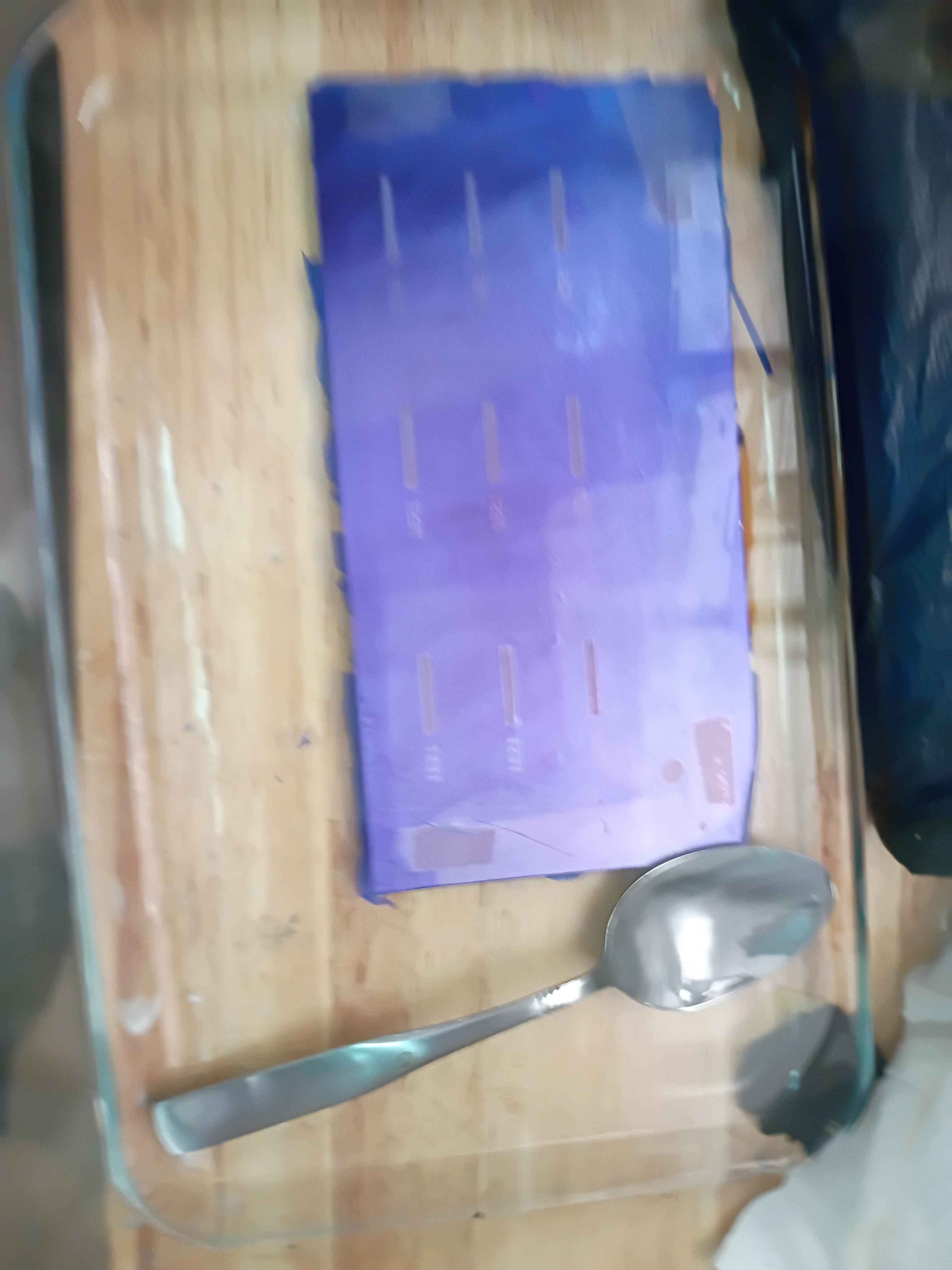
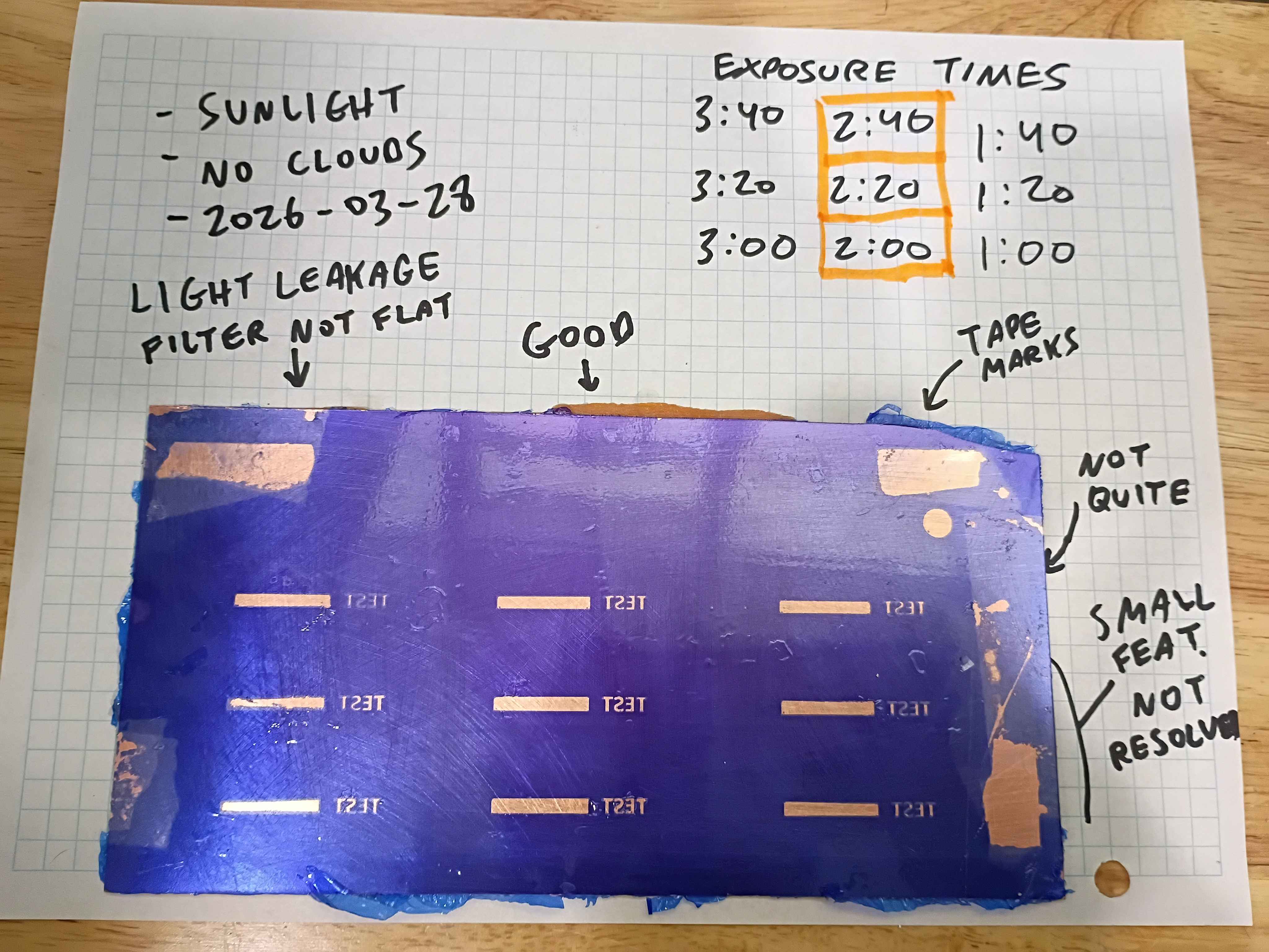
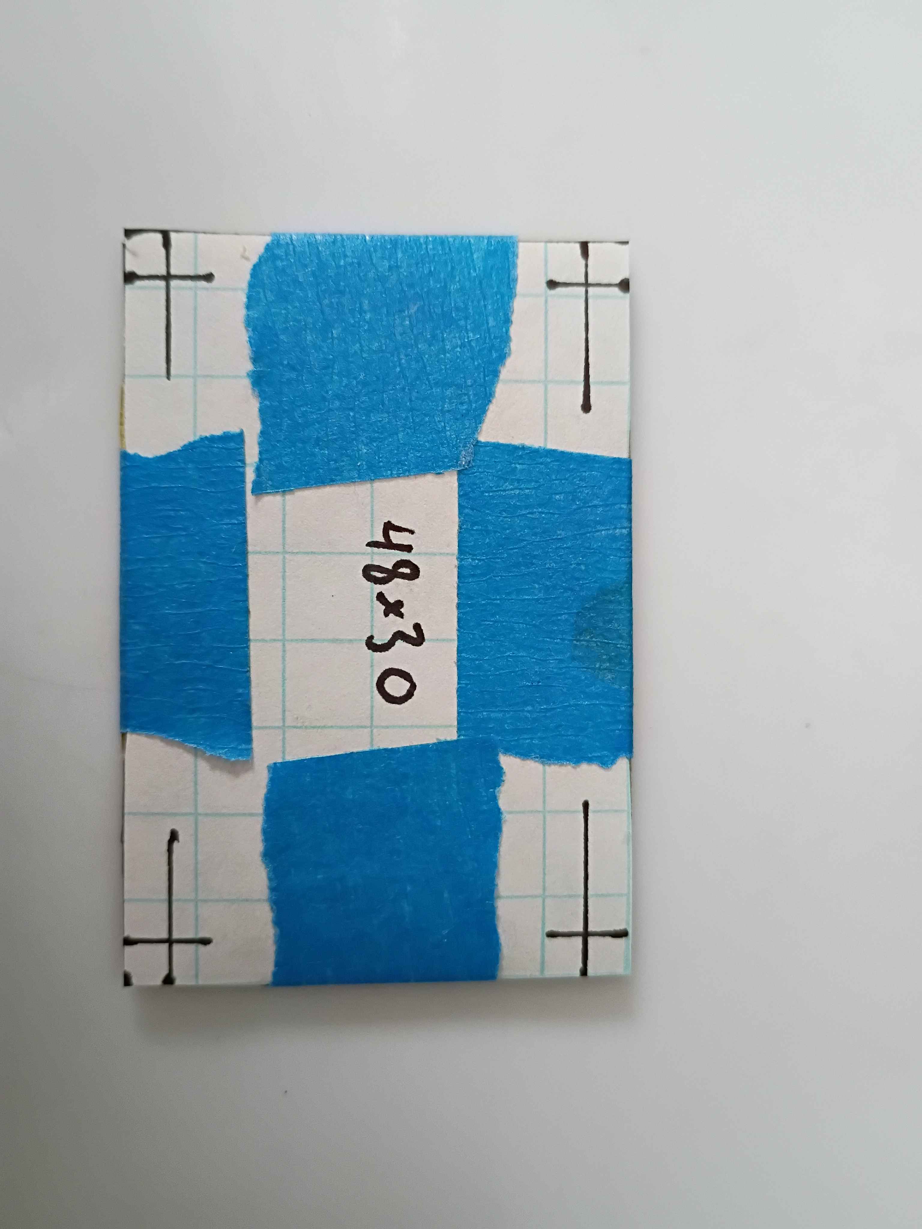
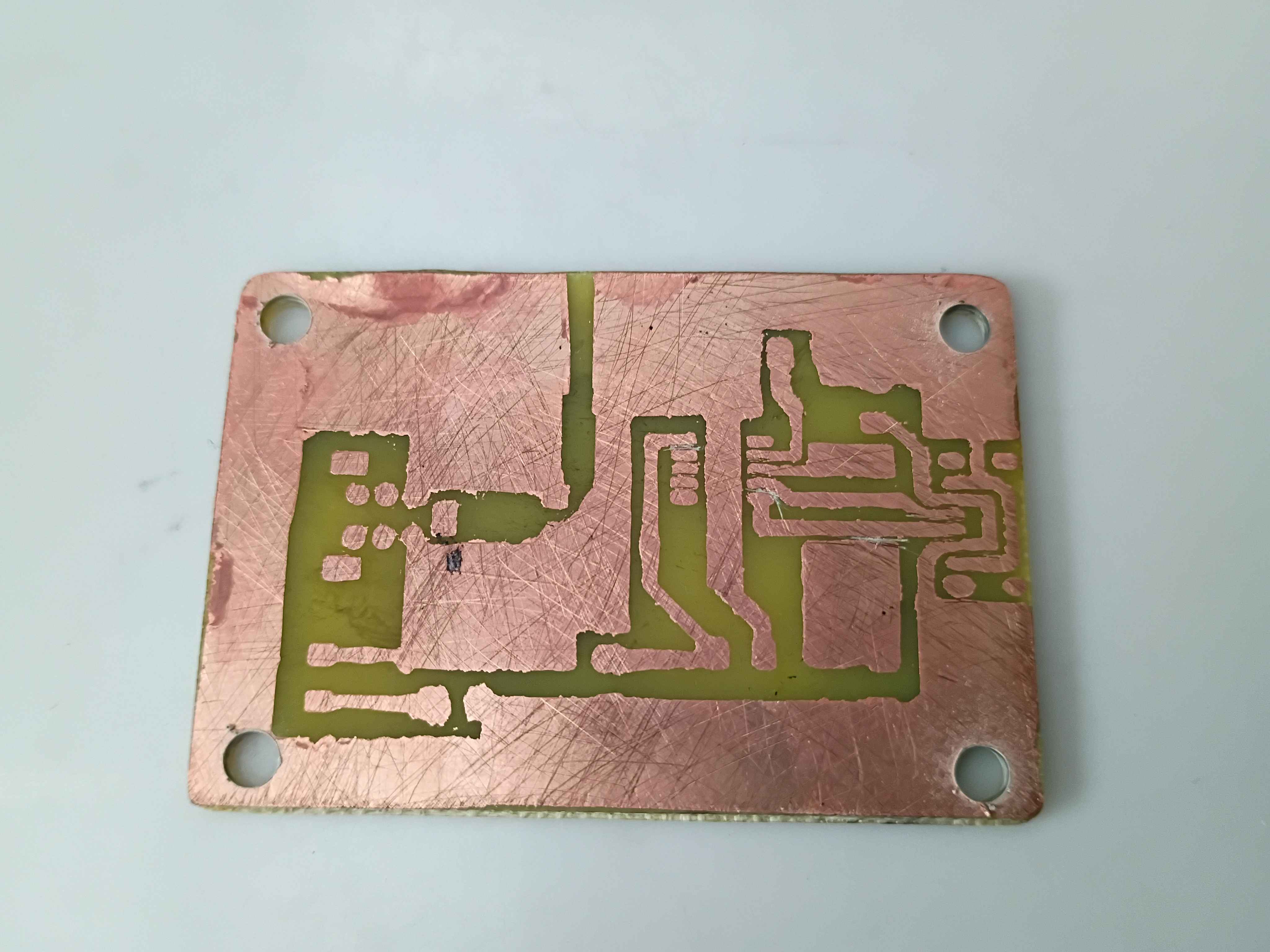
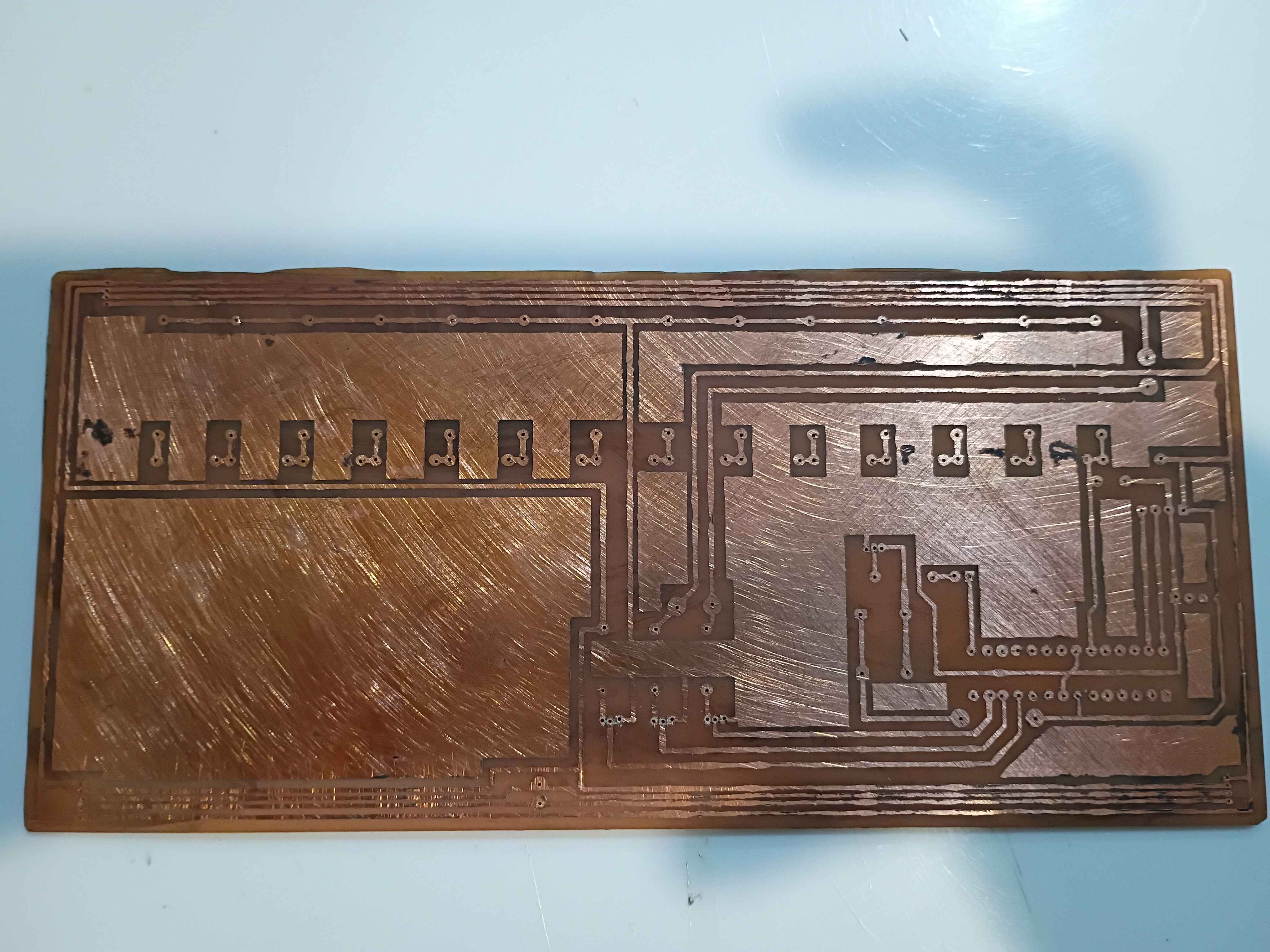
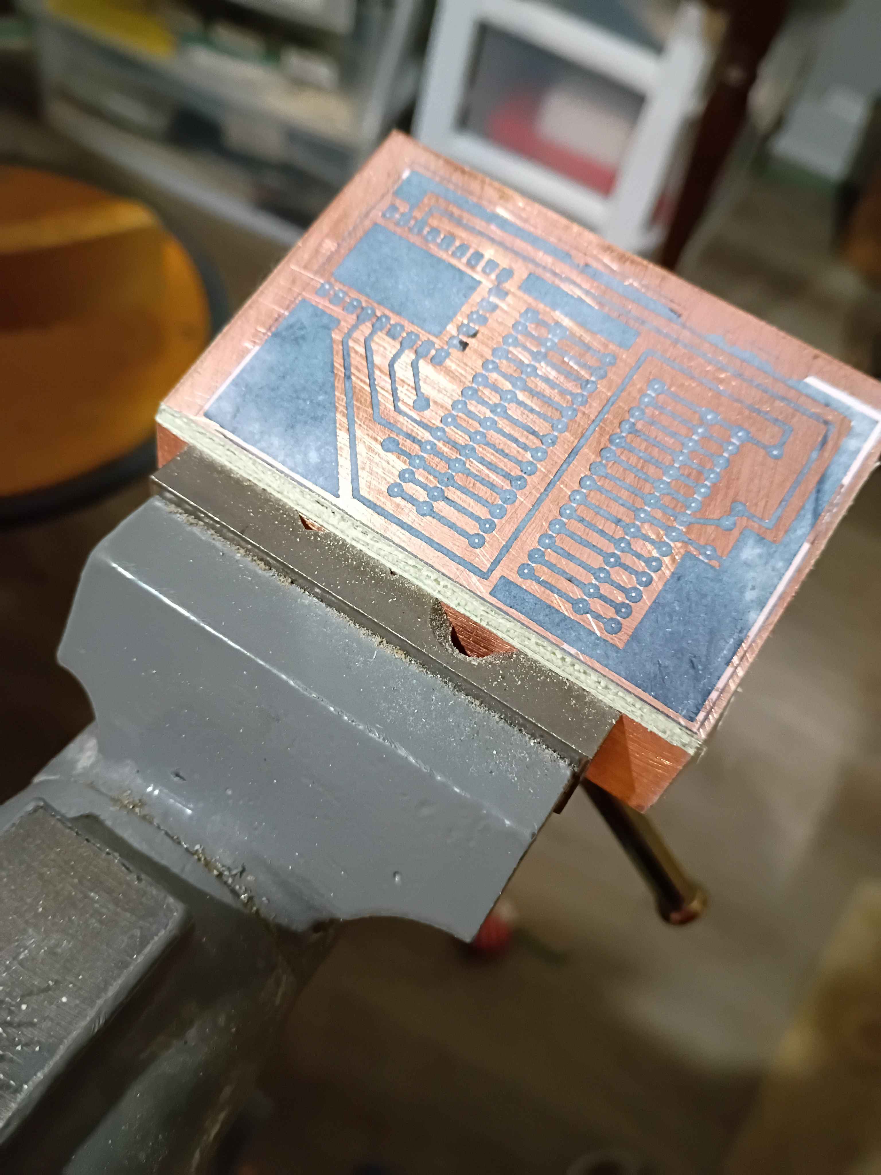
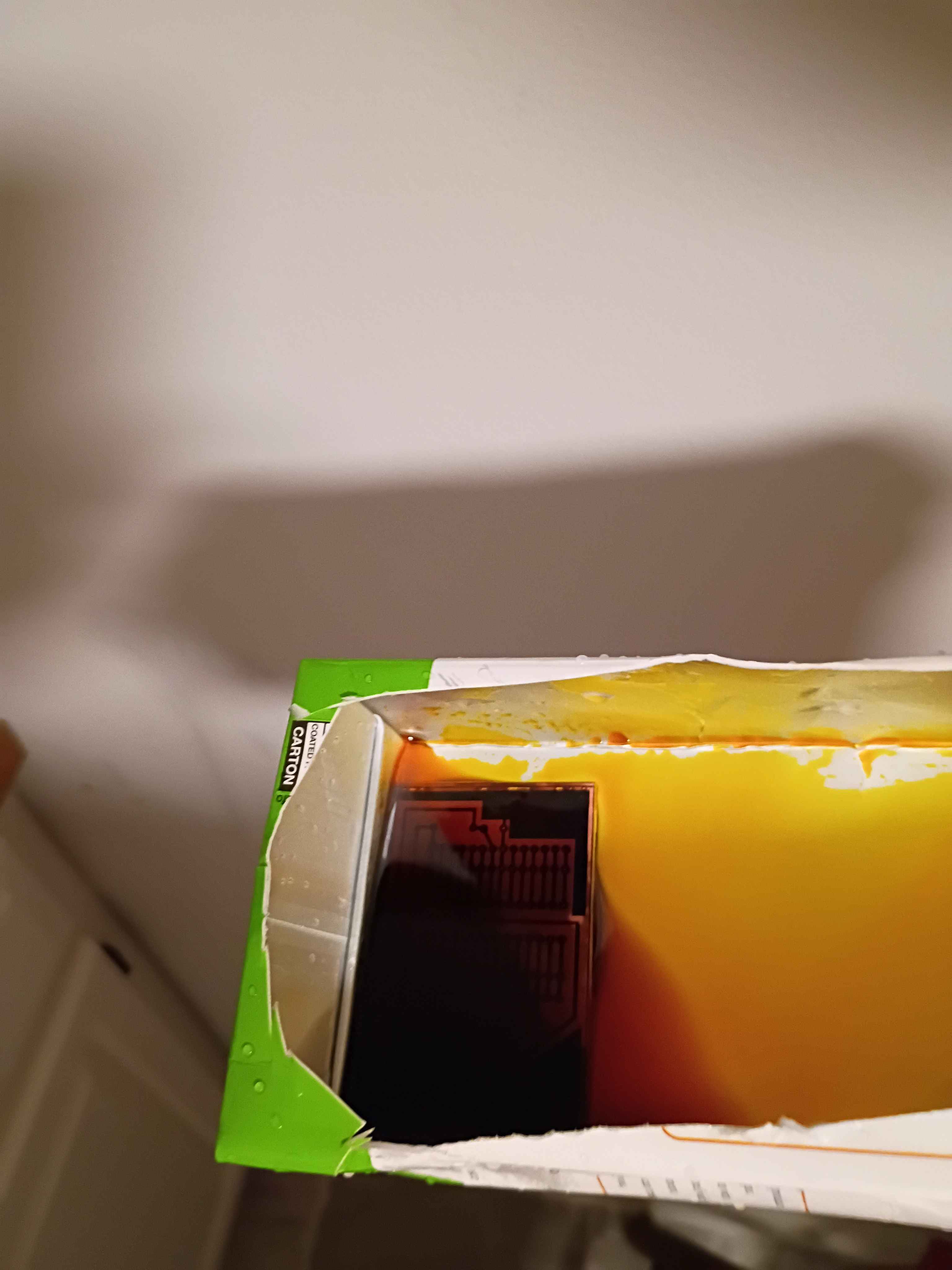
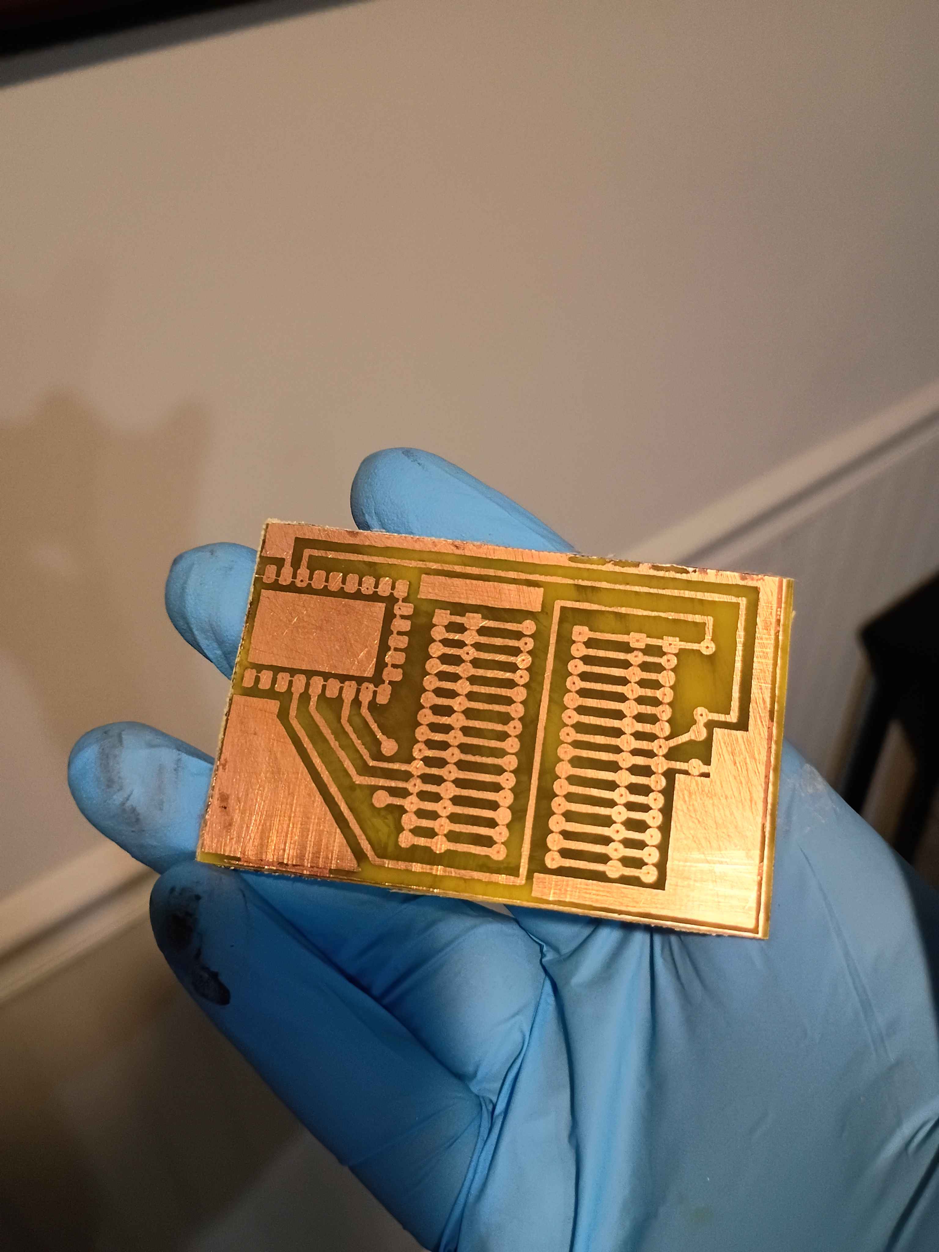
Re-attempted the use of dry film photoresist for mask transfer onto copper clad boards. Board was scuffed with 500 grit and then cleaned with acetone and IPA (actually I messed up the first film transfer and removed the failed attempt with acetone and wiped clean with IPA). The film was affixed mostly mechanically, with bubbles being removed by sliding them out by finger pressure. Limited heat was used, iron on low seemed not to help very much, though research suggests it helps the bond. A double layer of a light filter laser-printed on transparency sheets was taped to the surface and regions were exposed to the sun on this cloudless day in Bridgeport, CT (2026-03-28) for between 1:00 and 3:40 minutes. The filters were held flat to the surface by a thin acrylic sheet. After developing in 1L tap water with 1 tbsp dissolved washing soda for several minutes, the board was wiped dry. All the exposures >1 minute appear passable, though because the light filters were not pressed flat the entire time, the longer exposure times seem to have experienced some light leakage, though that could likely be avoided with a better clamping setup. Qualitatively the 2:20 exposure time looks best, with the 0.4mm features in the text being well defined. This is more than enough fidelity for most circuit traces and IC package pin spacing. Exposures below 2:00 also seem reasonable though the edges are not well resolved. I think this is because the photoresist is not sufficiently cured along the edges. The conclusion is that this method of transferring a copper mask with relatively fine features can be used successfully without even a UV cure station. It would appear able to resolve smaller features with a greater degree of success than toner transfer. If I were to use this in the future, I would recommend clamping a thick glass panel on the outer surface to keep the light filters pressed flat and cure for roughly 2:30. 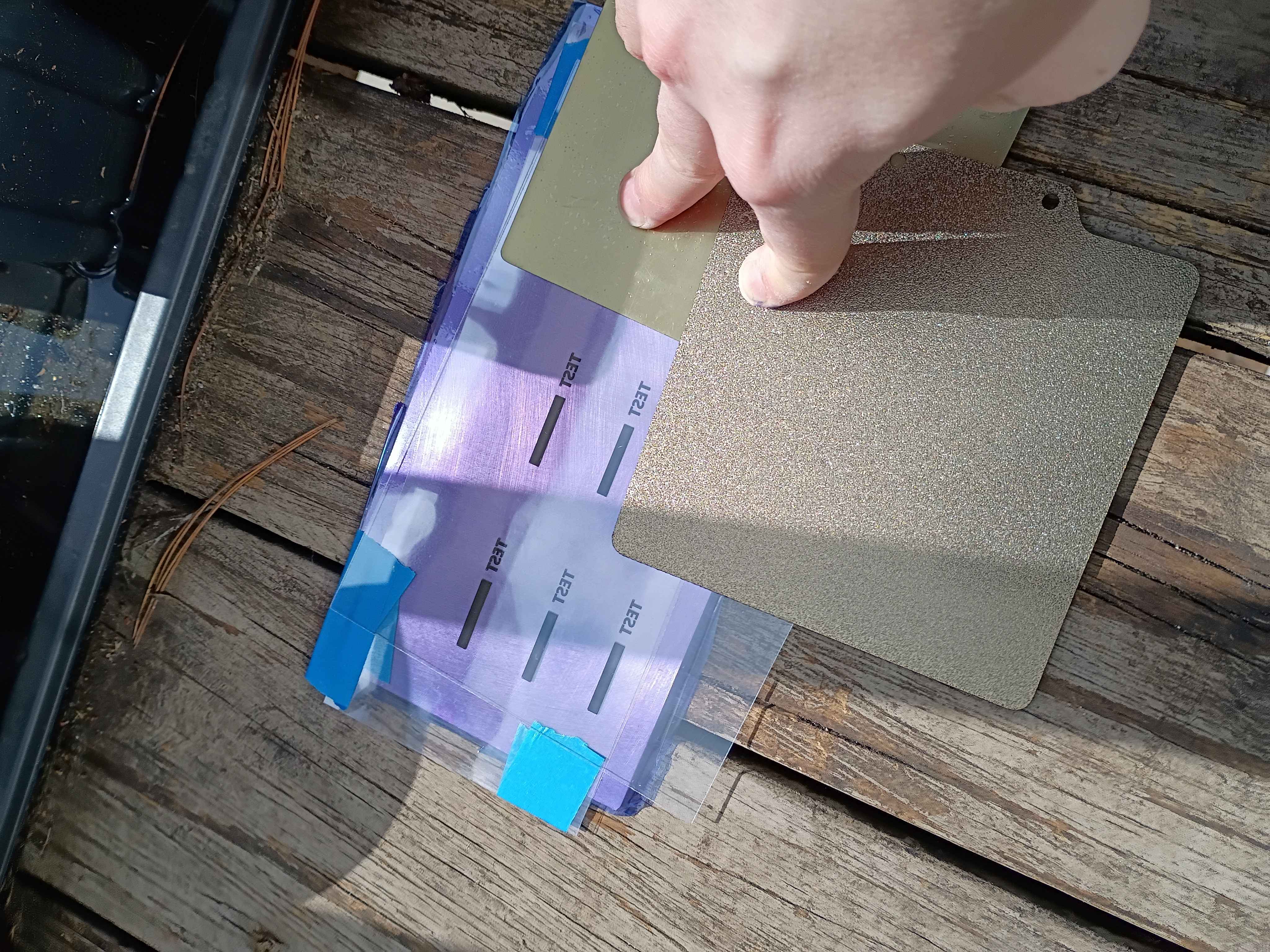
Printed and installed (with absolutely none of the correct hardware) the "pltr v2" plotter conversion to the old Ender3. Did a quick test and proved that it would work in theory to apply Sharpie as etch-resist for basic PCB production. Have to figure out how to generate the gcode for the mask with a preset X Y Z offset, but maybe I can cheat by zeroing the printer at a certain location. For reference the Sharpie lines are a bit under 1/32 inch wide, which I think will work for SOIC packages but probably not TSSOP. Still very cool. See video. 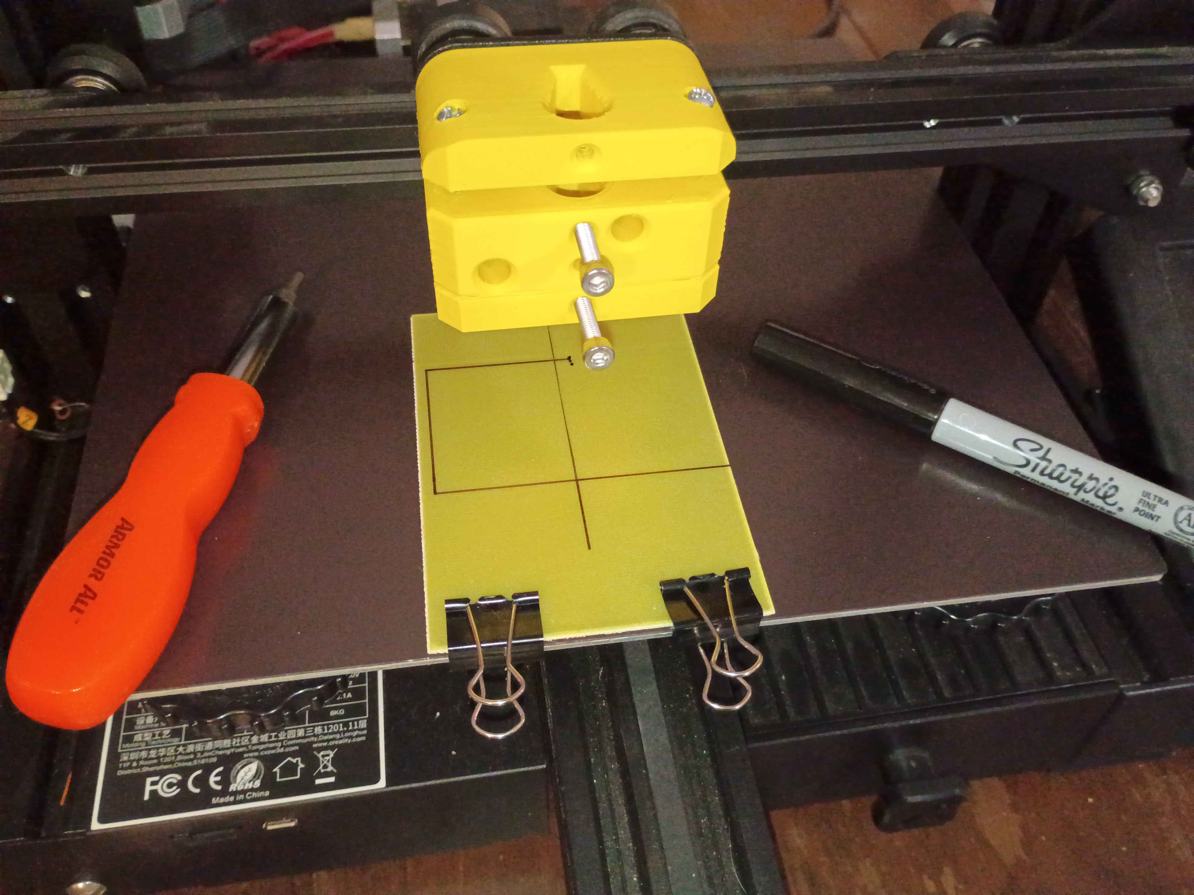
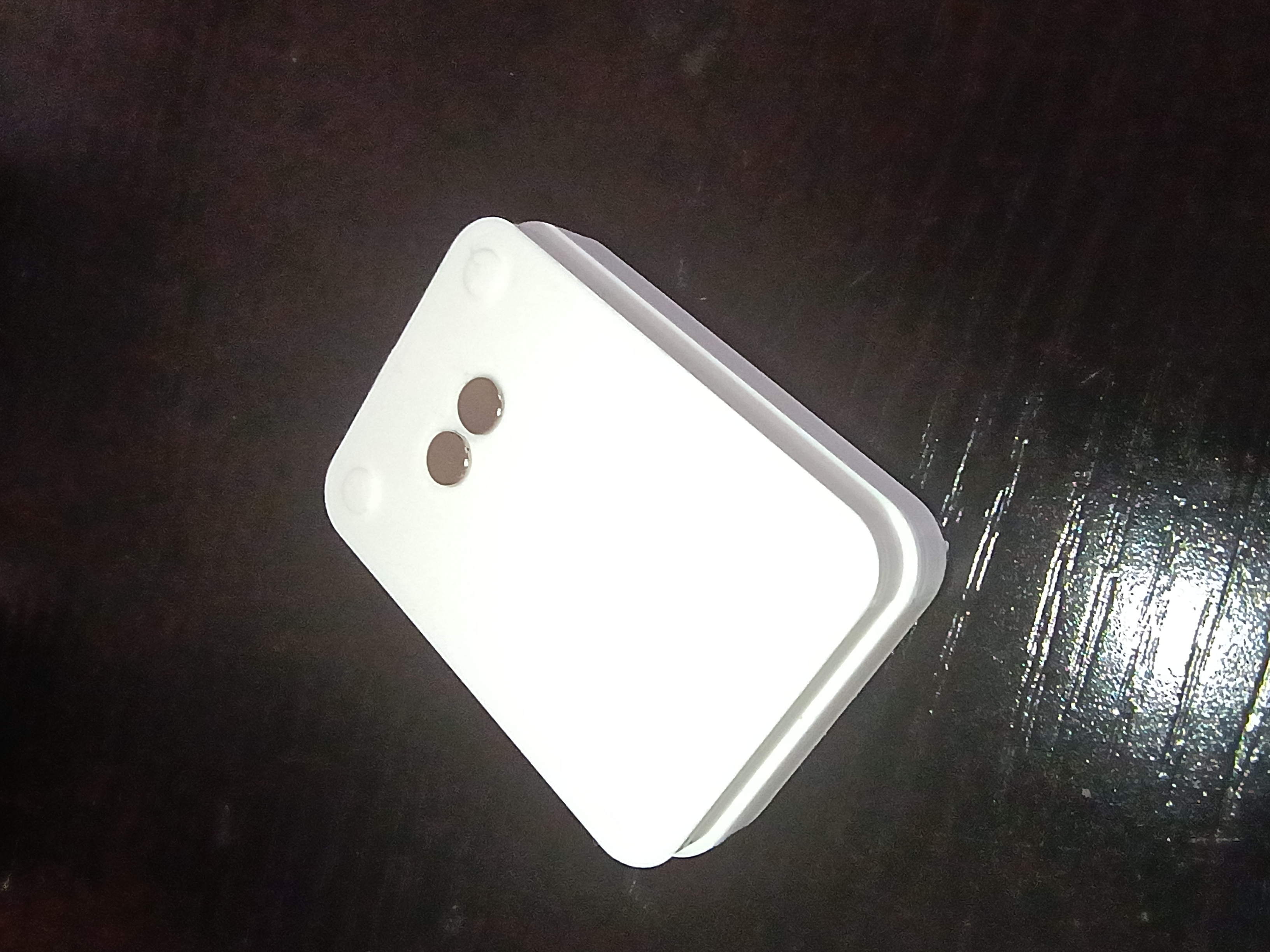
Mocked up preliminary button and housing components in 3D. Buttons need some kind of retention feature to prevent them contacting the eventual hall effect sensor. 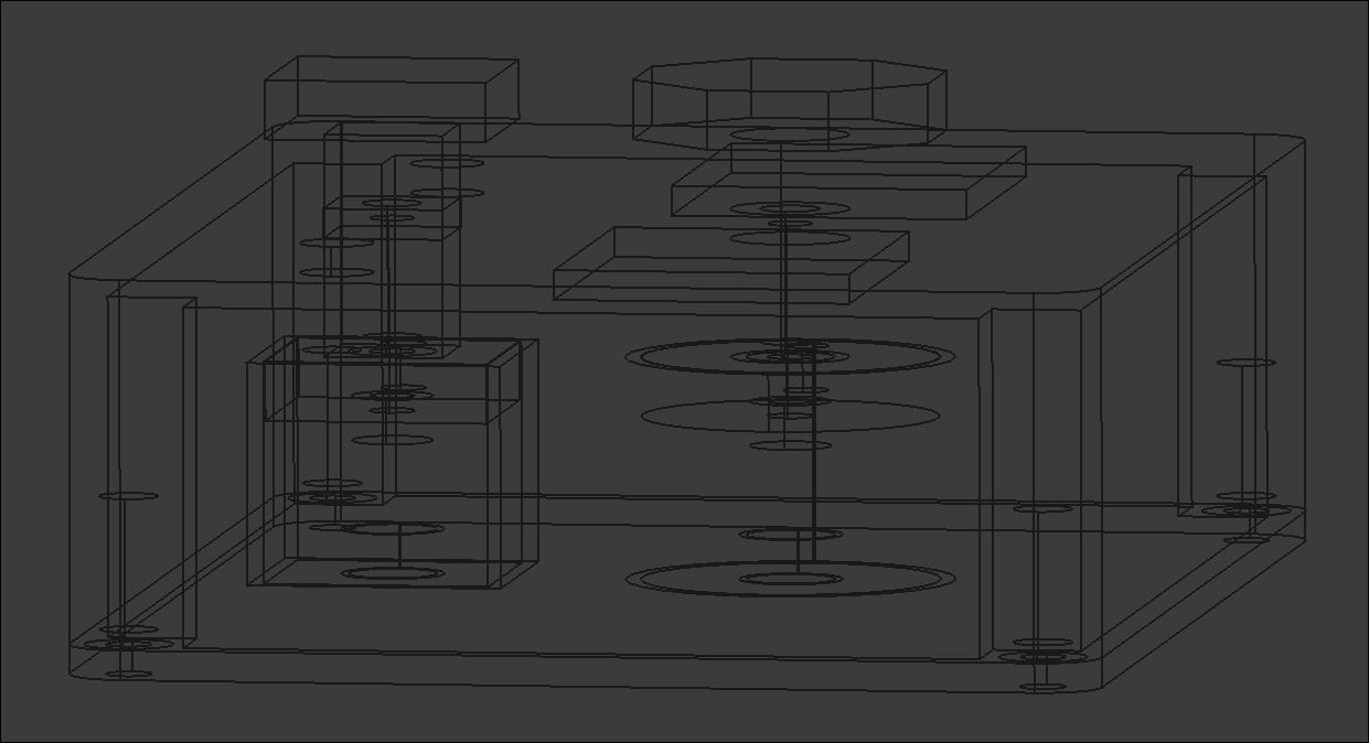
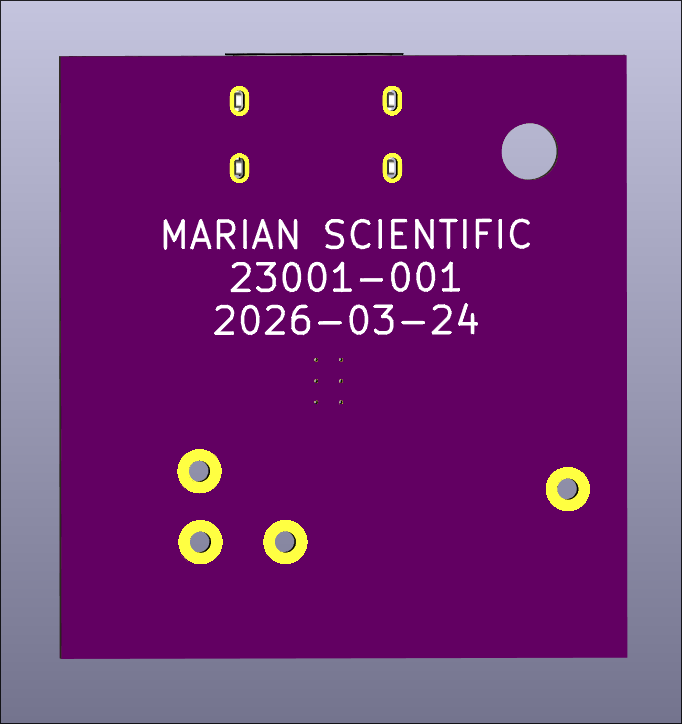
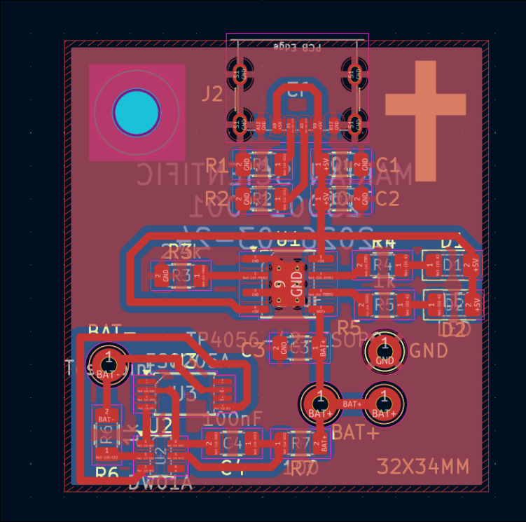
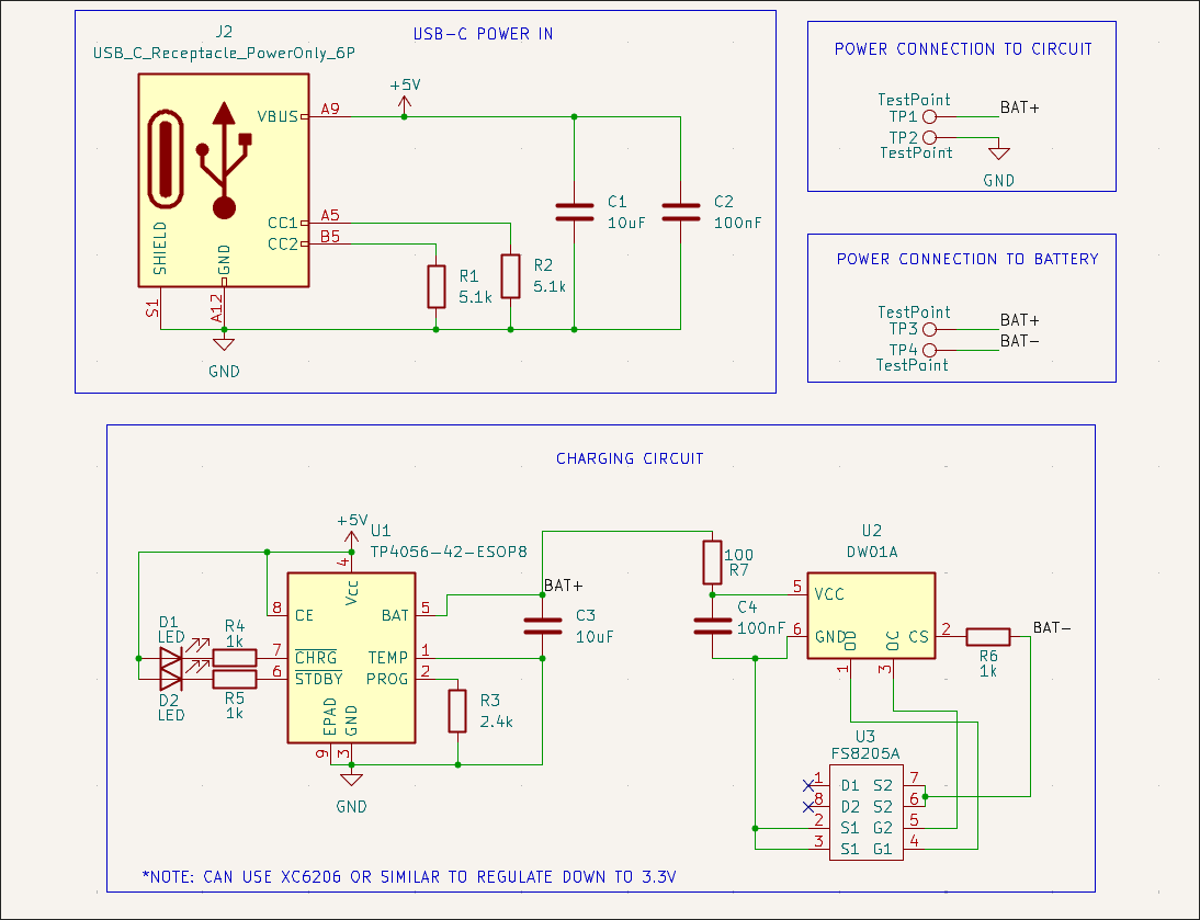
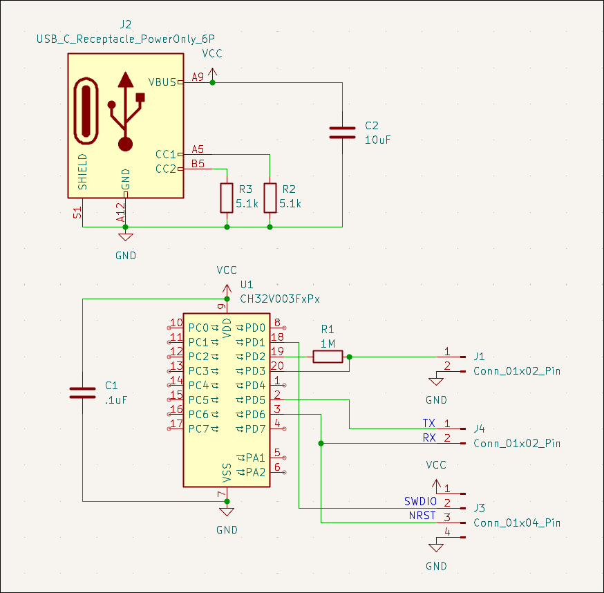
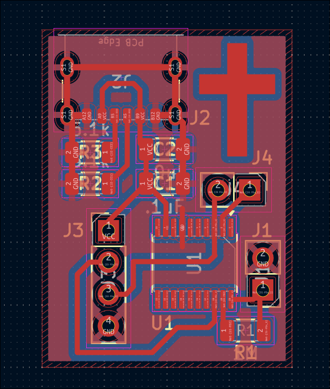
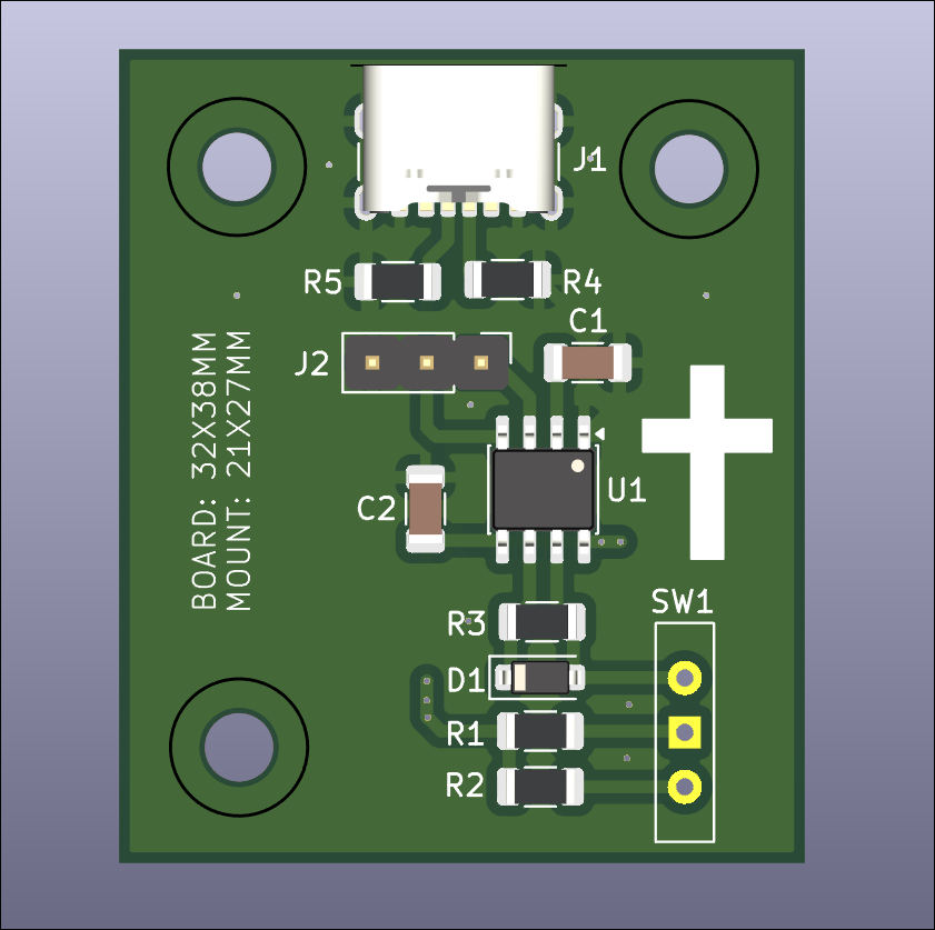
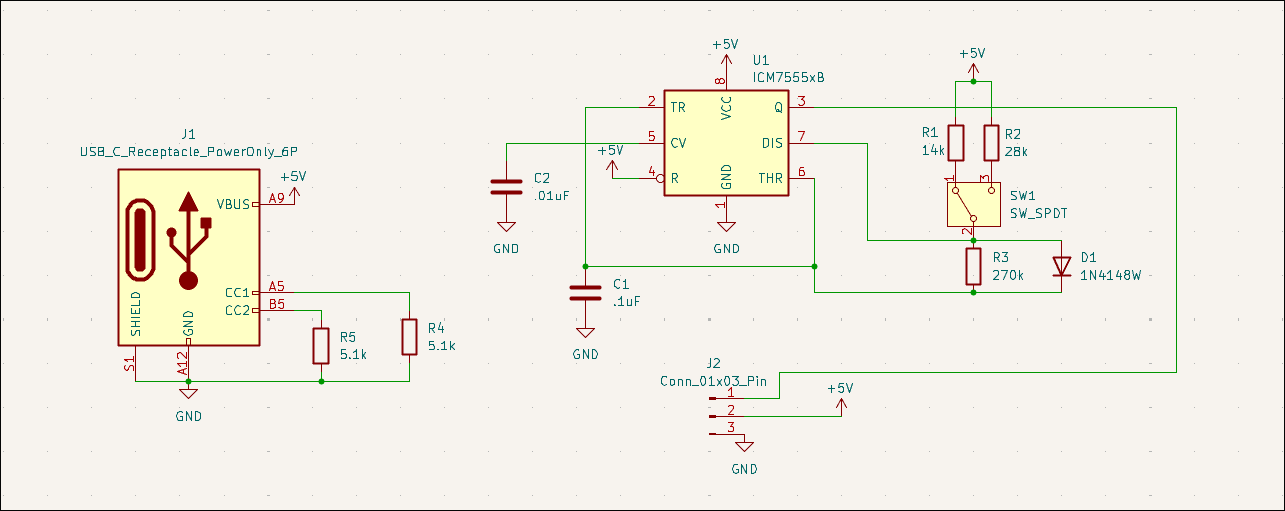
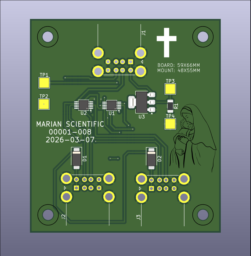
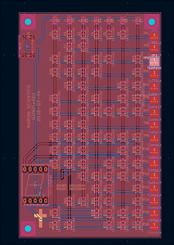
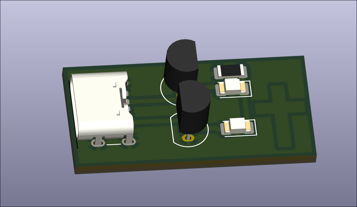
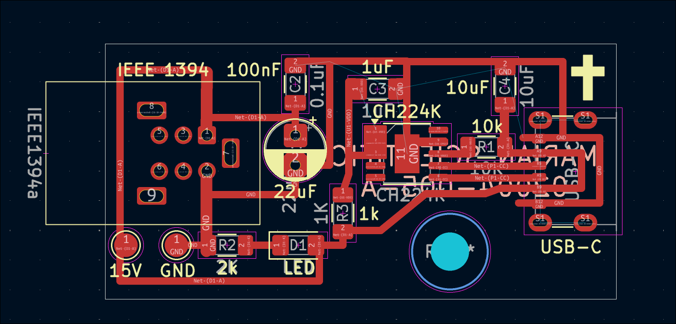
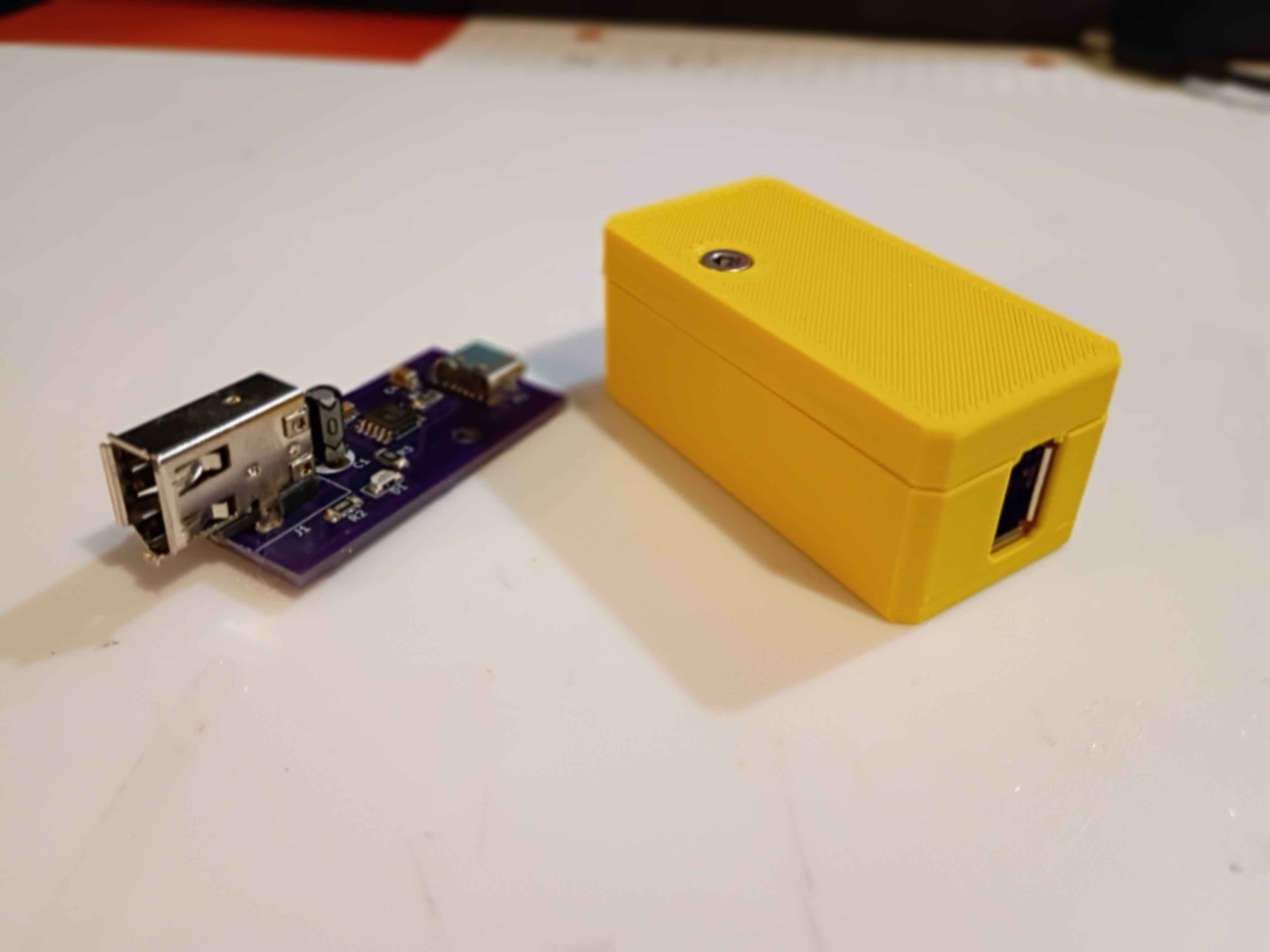
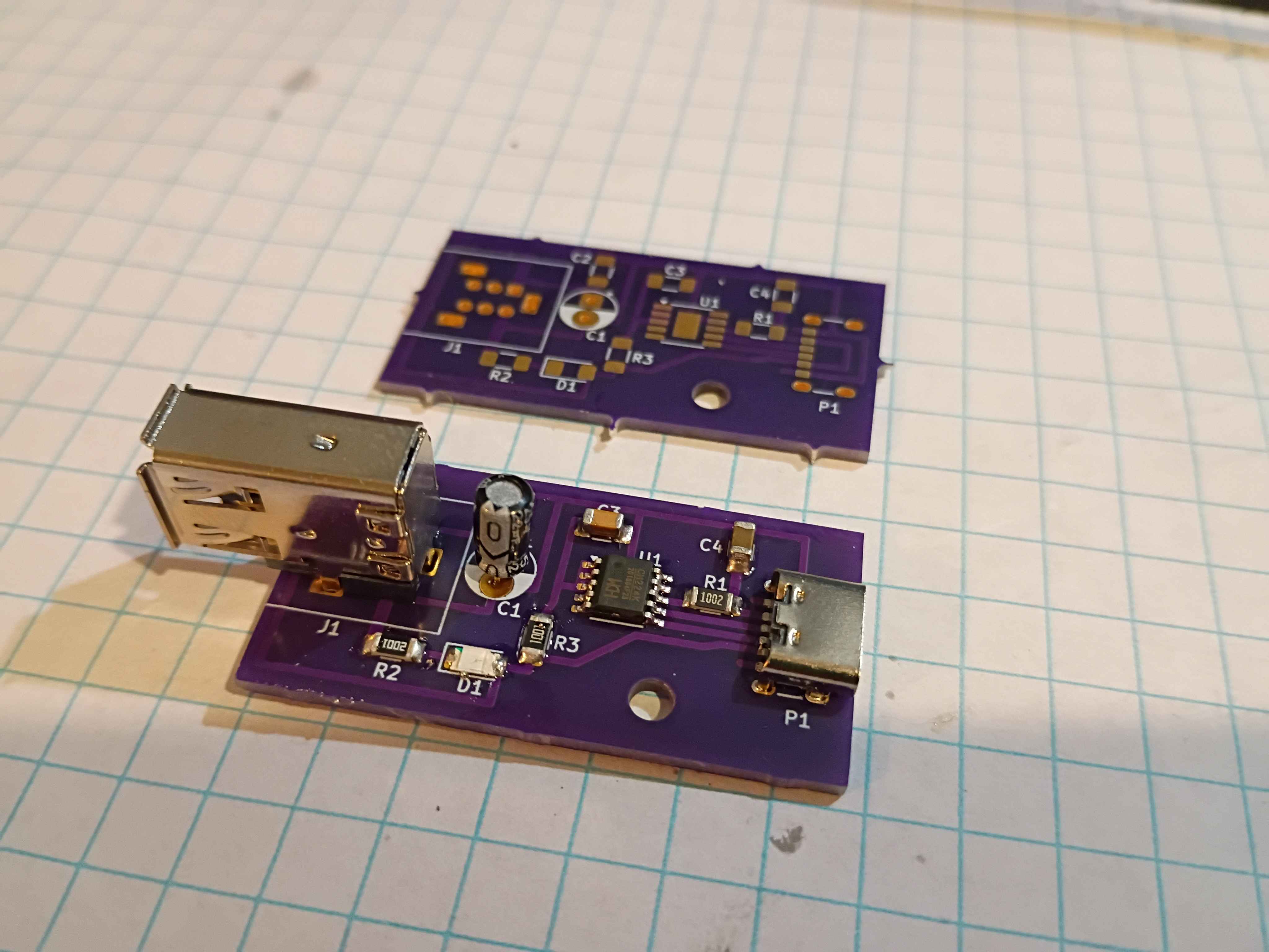
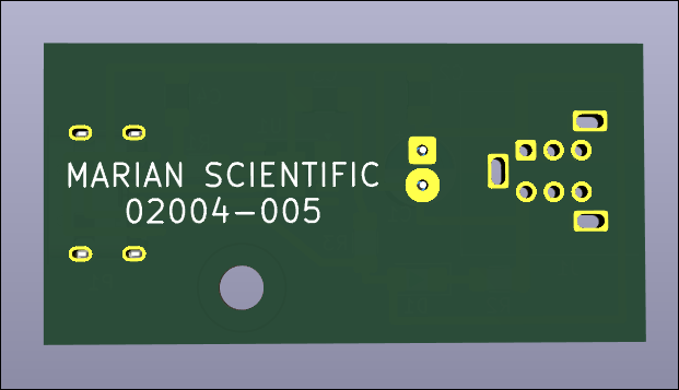
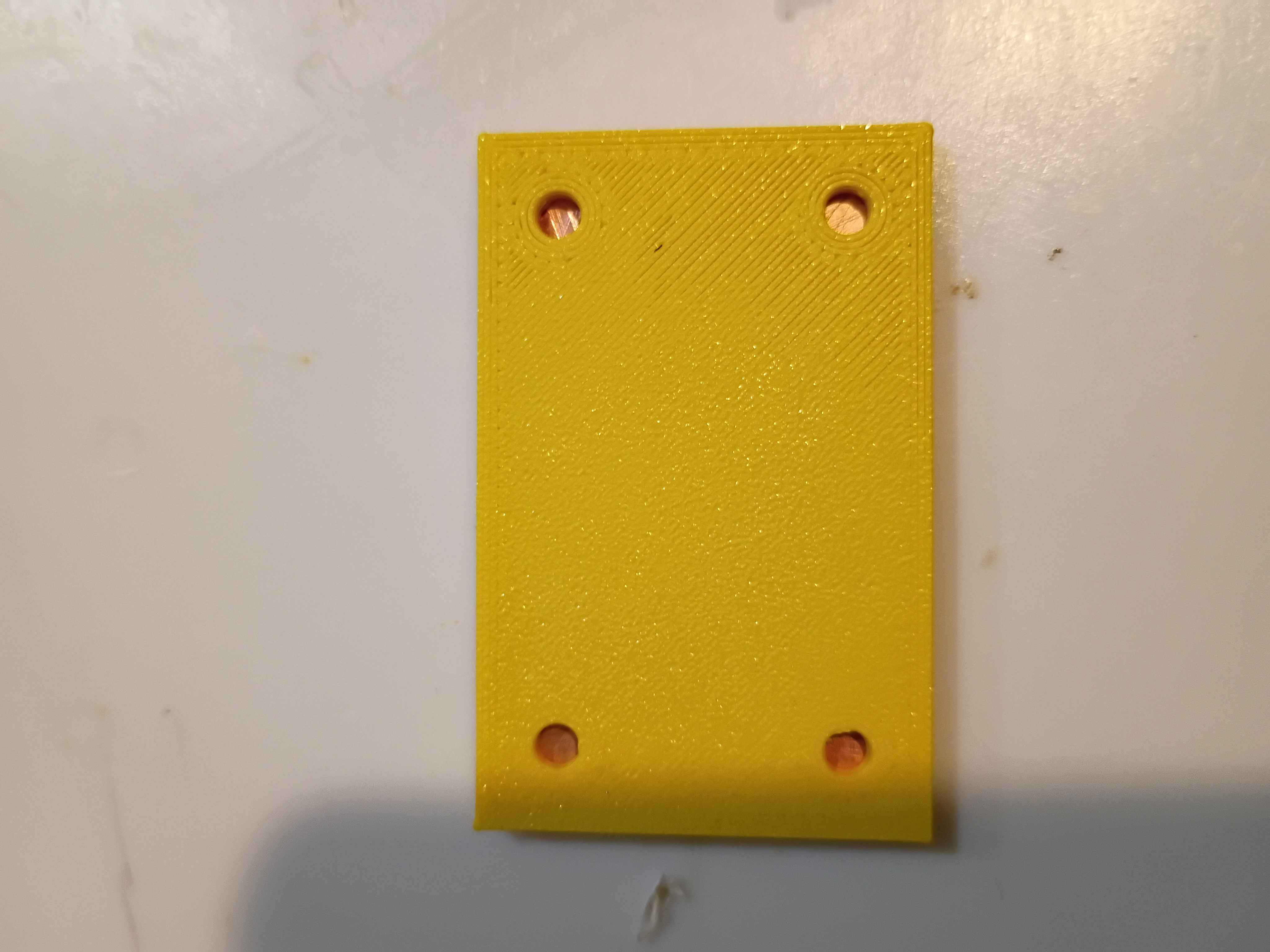
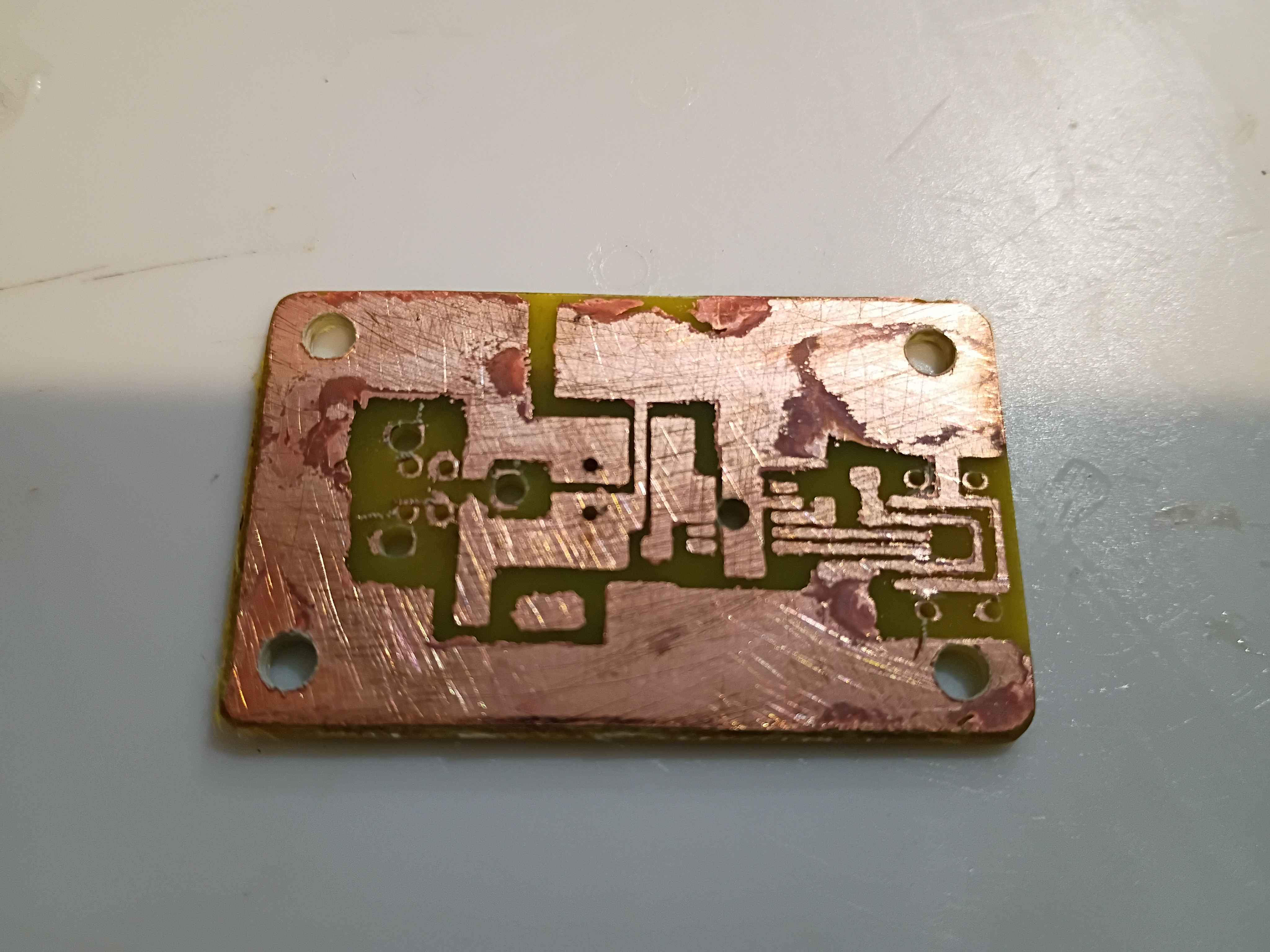
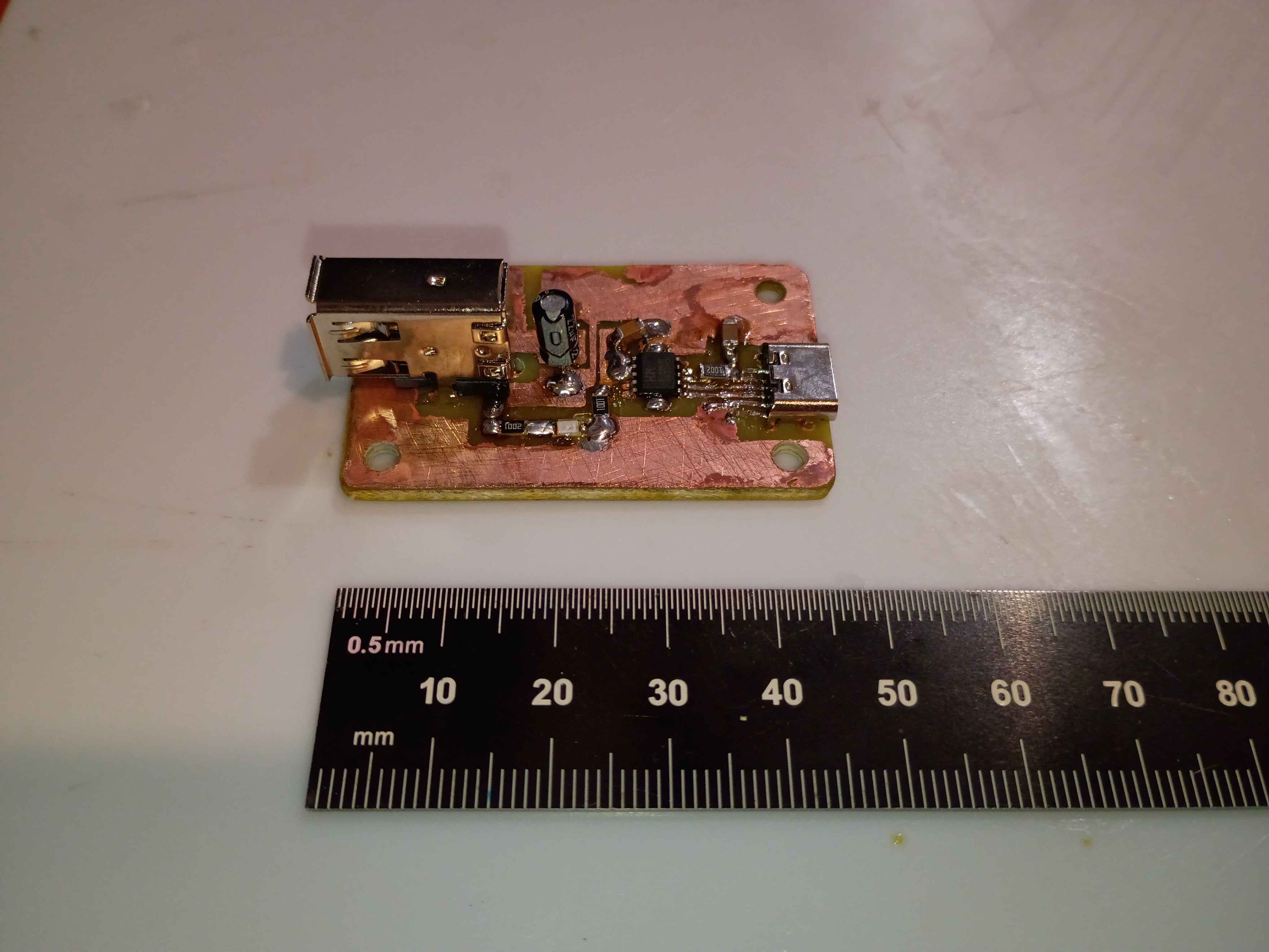
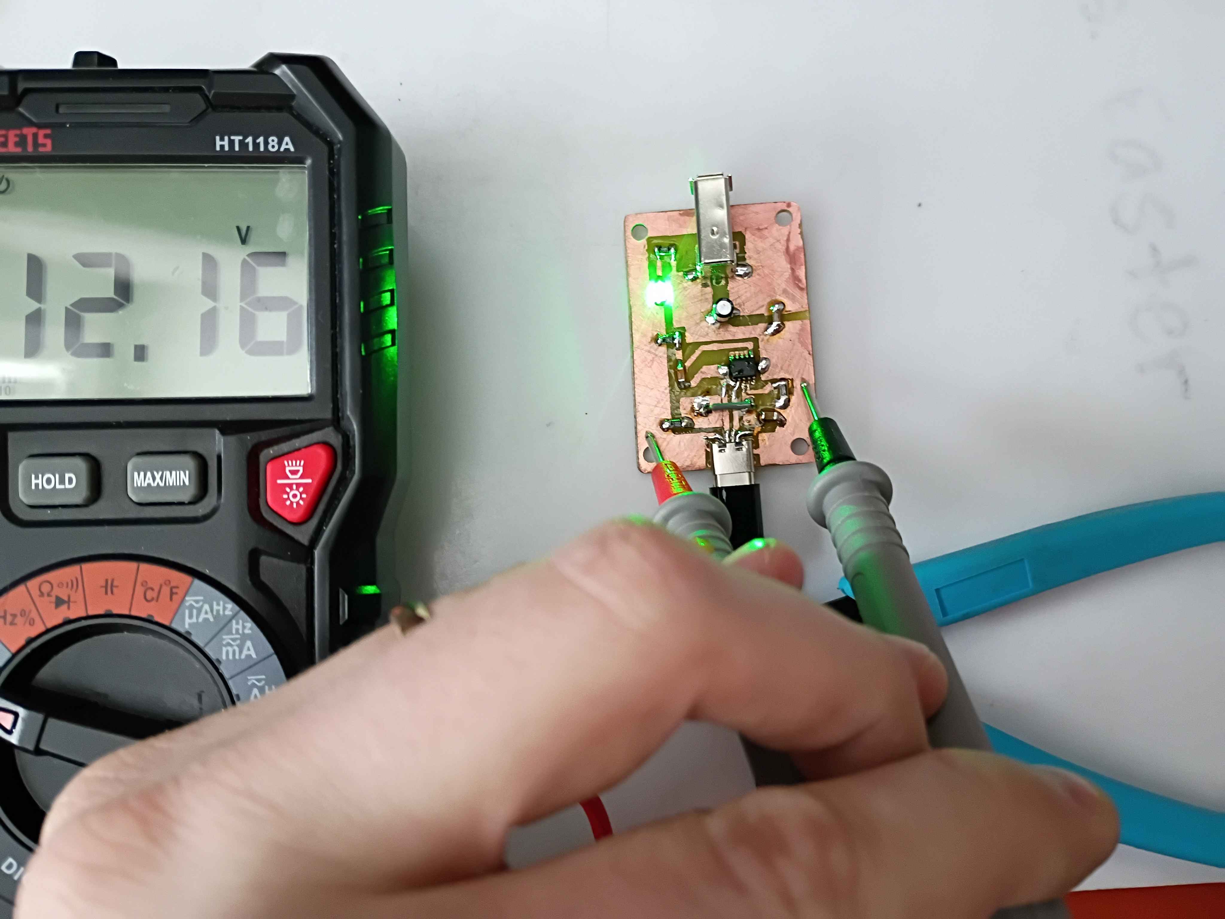
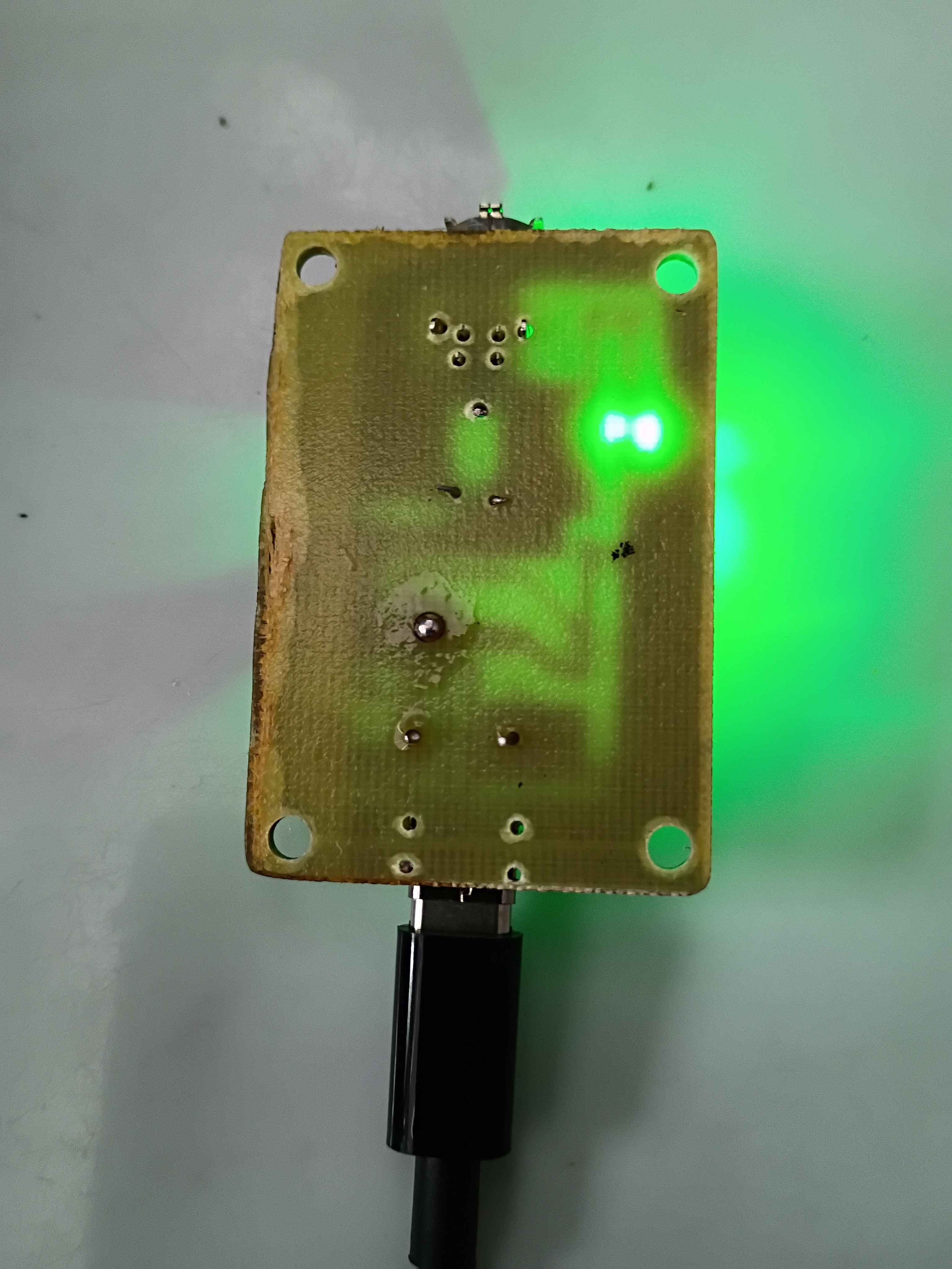
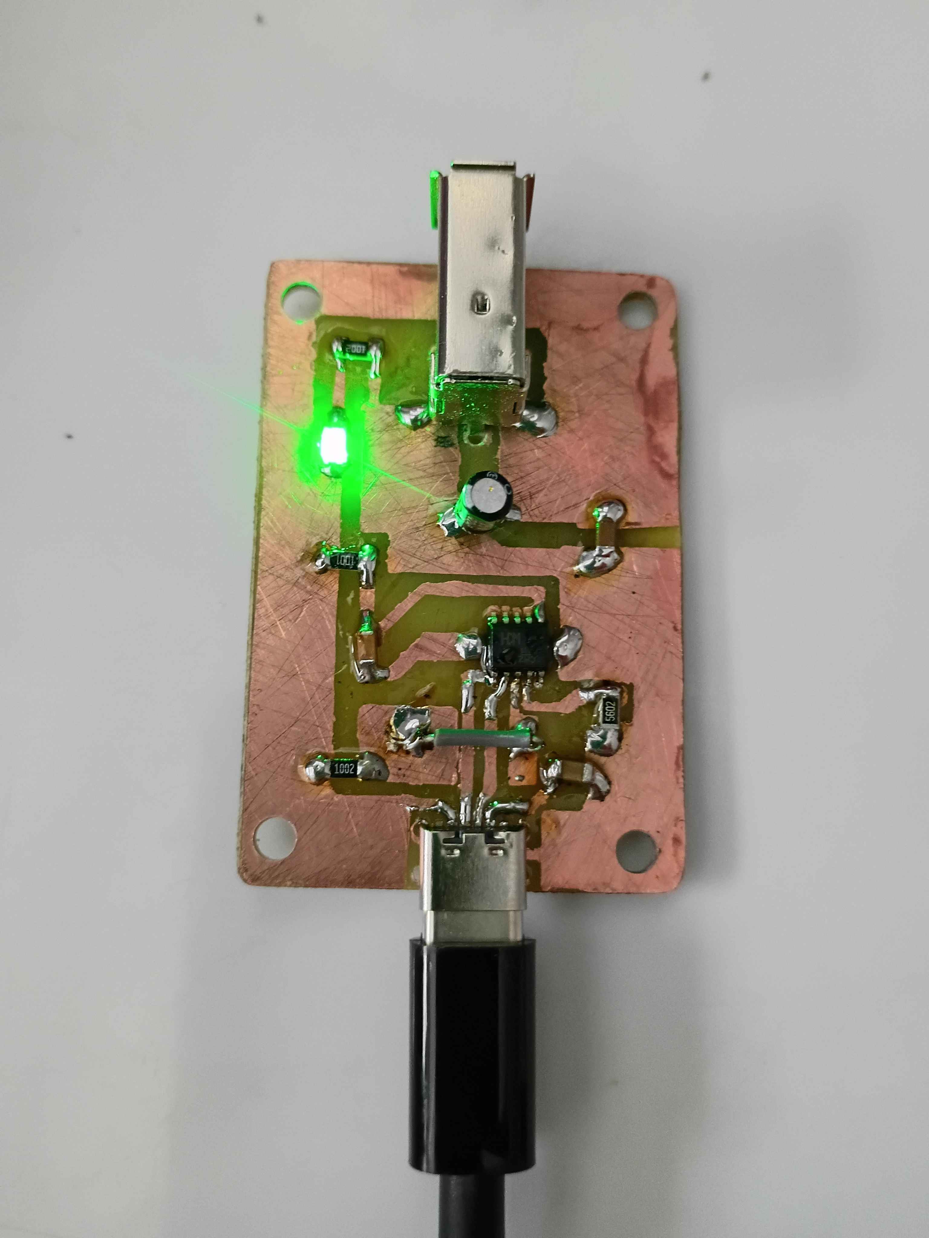
Designed USB-C LiPo charging and power delivery test board using TP4056, DW01A & FS8205. Ordered on OSHPark and saved full-size version as new MS KiCAD template for future use if the test board is successful. This will be the power basis for all near-term handheld math manipulatives. Design based largely on the linked schematic here. 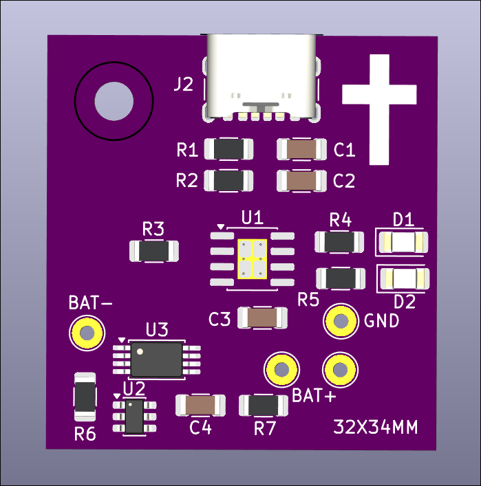
Updated printed config files to improve print quality and seemingly avoid some common print failures I was having. Reprinted 04002-001 and 04002-002 dog bag holder with a slightly larger internal diameter as a test print. 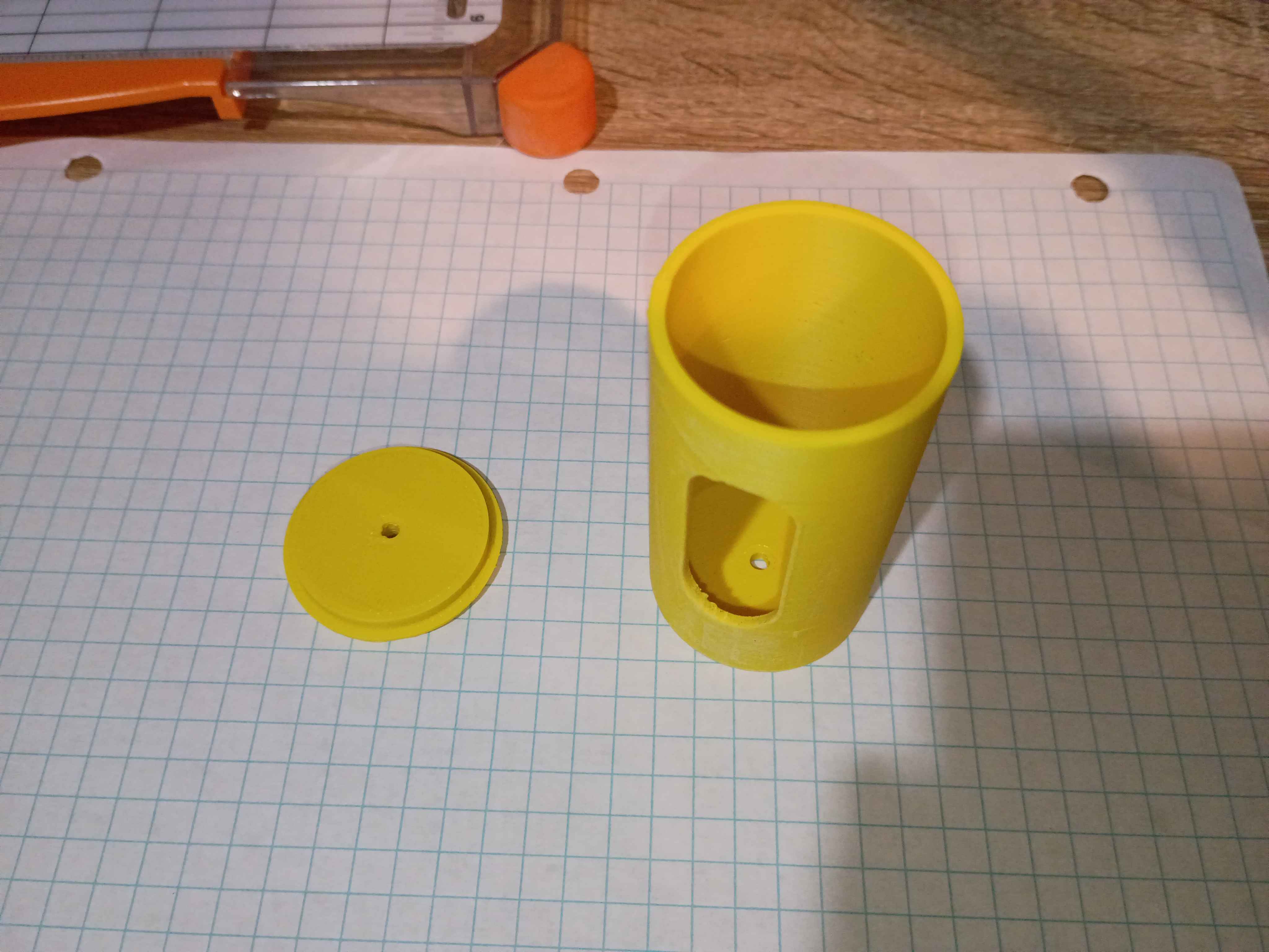
Designed and printed small (2cm) 3D geometric primitives for a client. Very rapid prototyping effort. 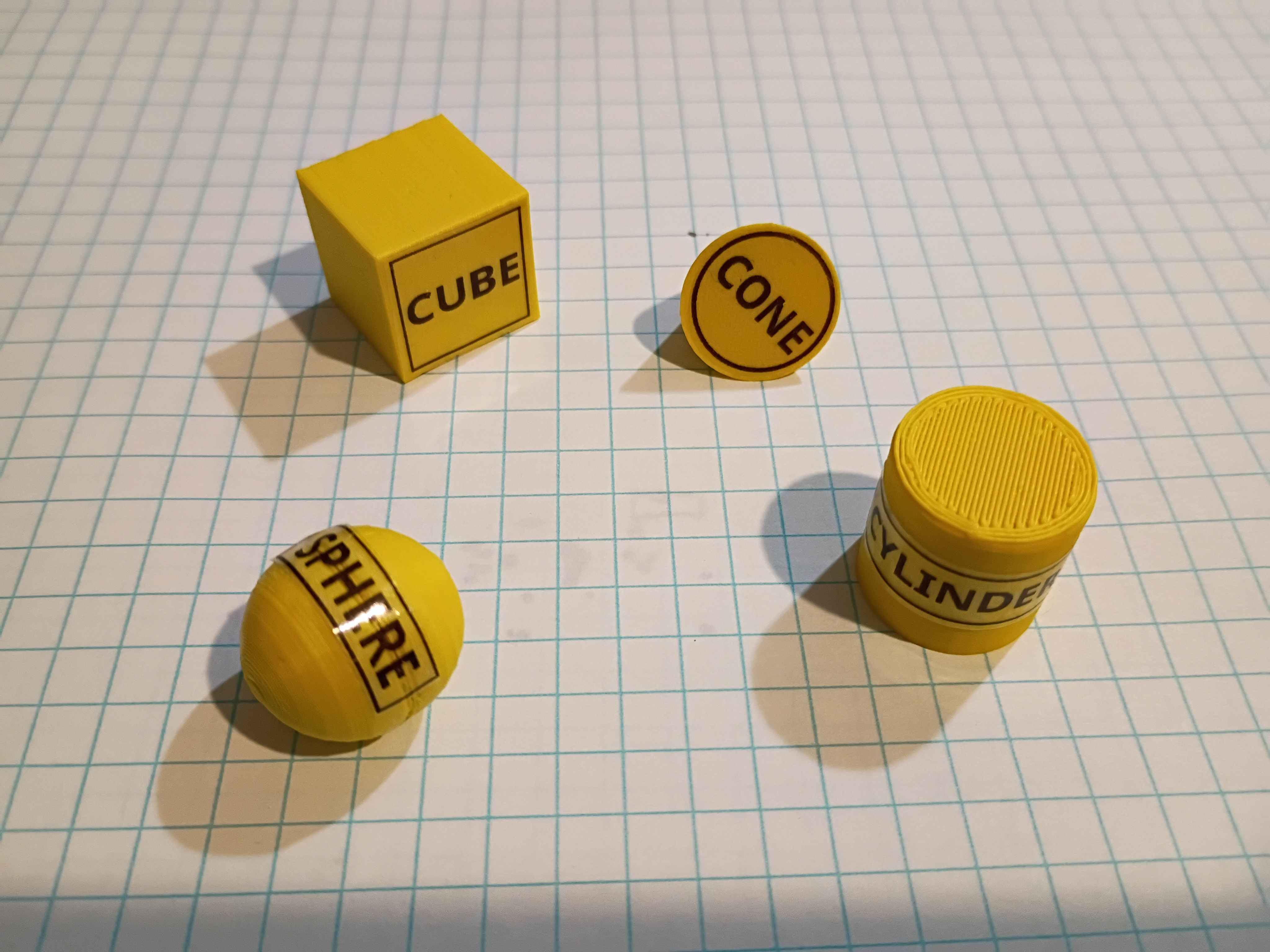
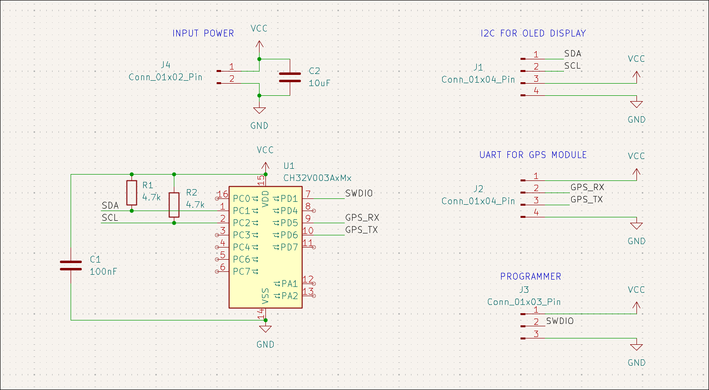
Designed UART GPS readout board to OLED display using CH32V003A4M6. 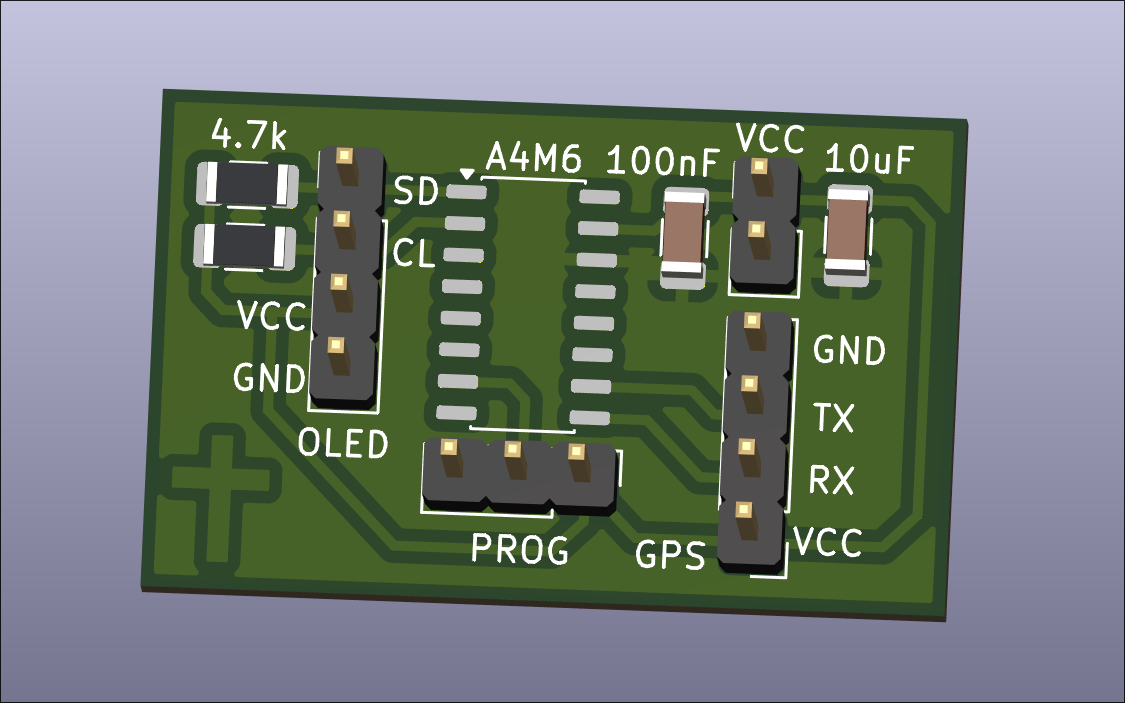
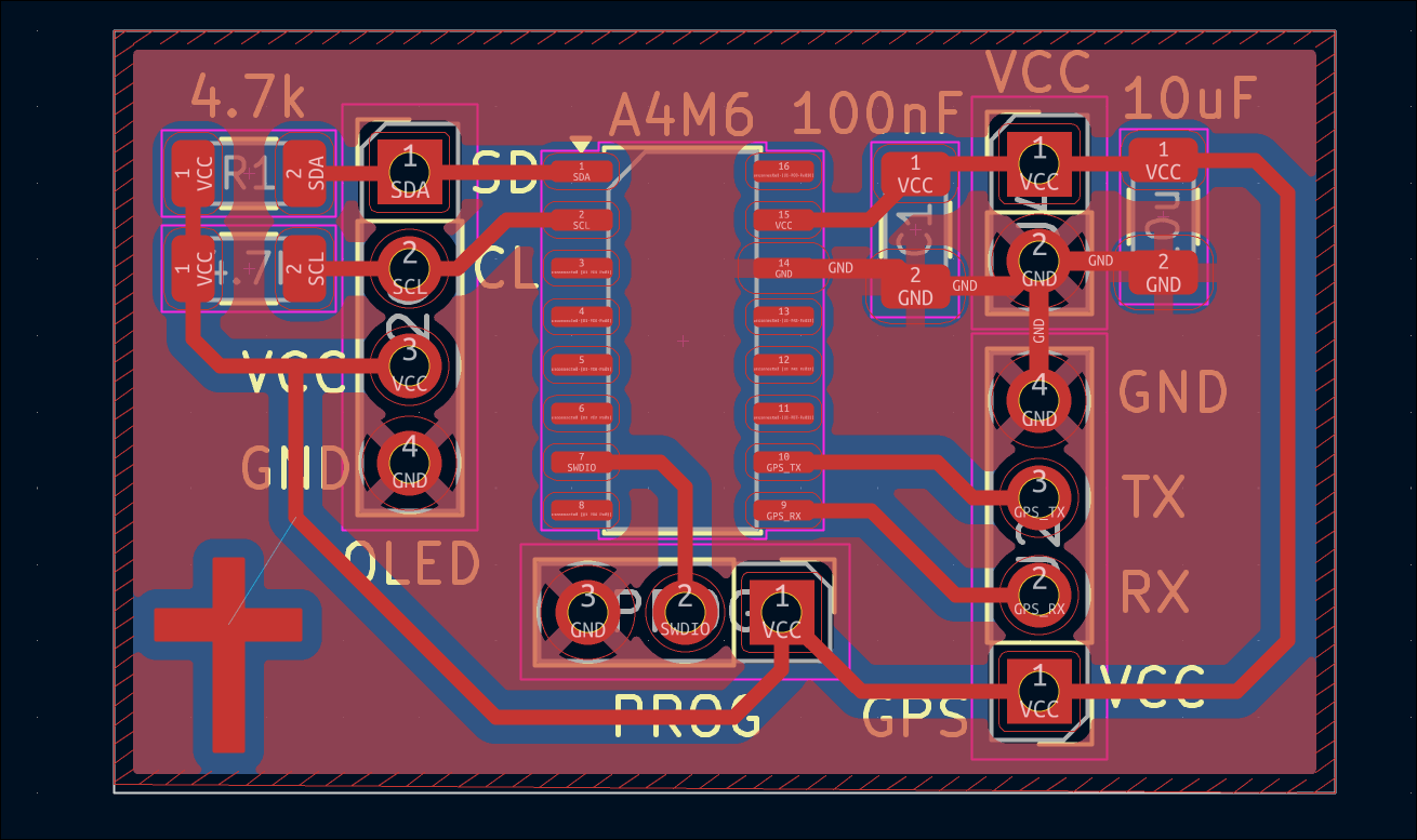
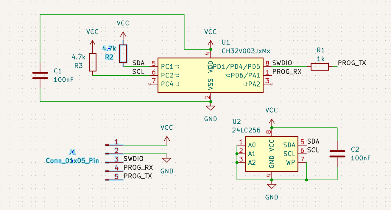
Designed simple test board for generic *24C256 (BL24C256) EEPROM attached to CH32V003J4M6. To be used alongside LinkE programmer for testing. 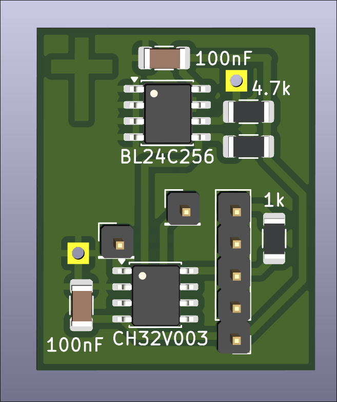
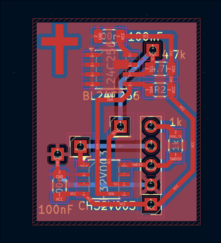
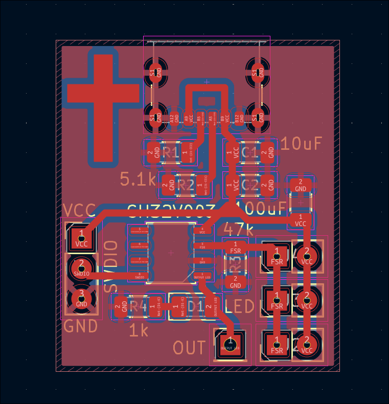
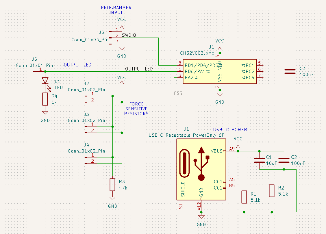
Designed force-sensitive resistor (parallel) weight measurement board that signals an output when the force is above some threshold level. 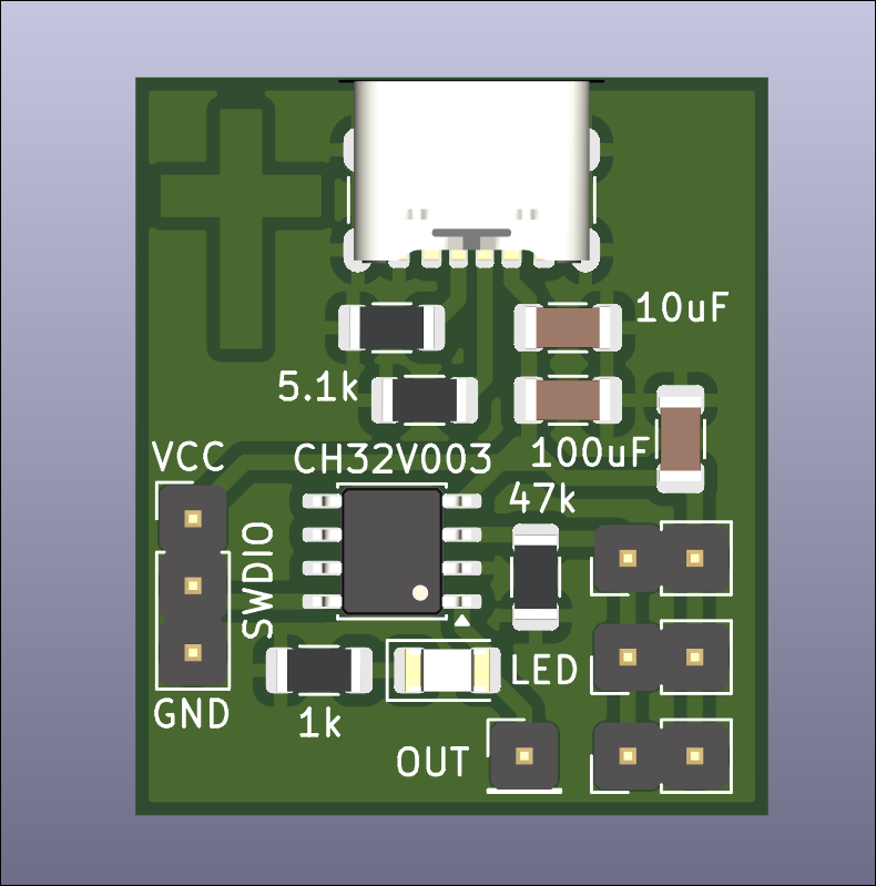
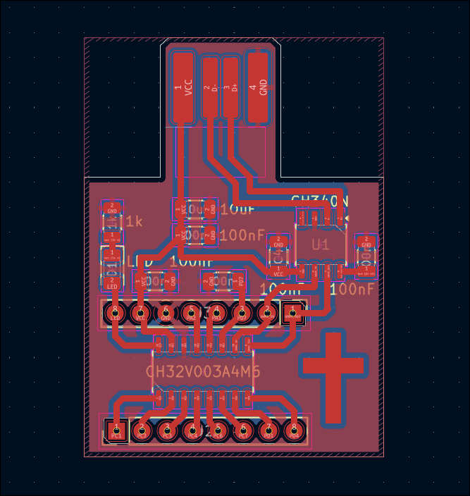
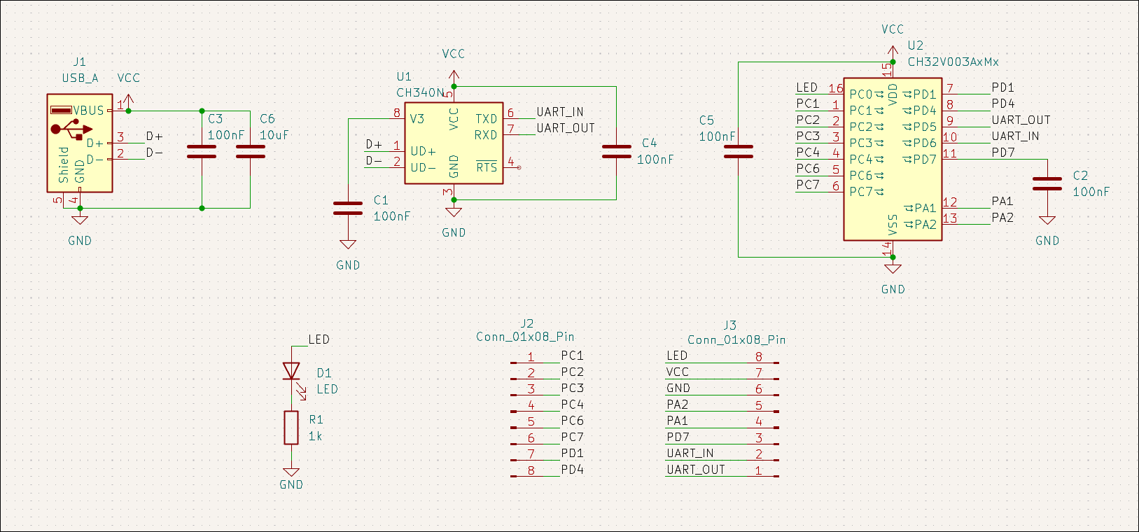
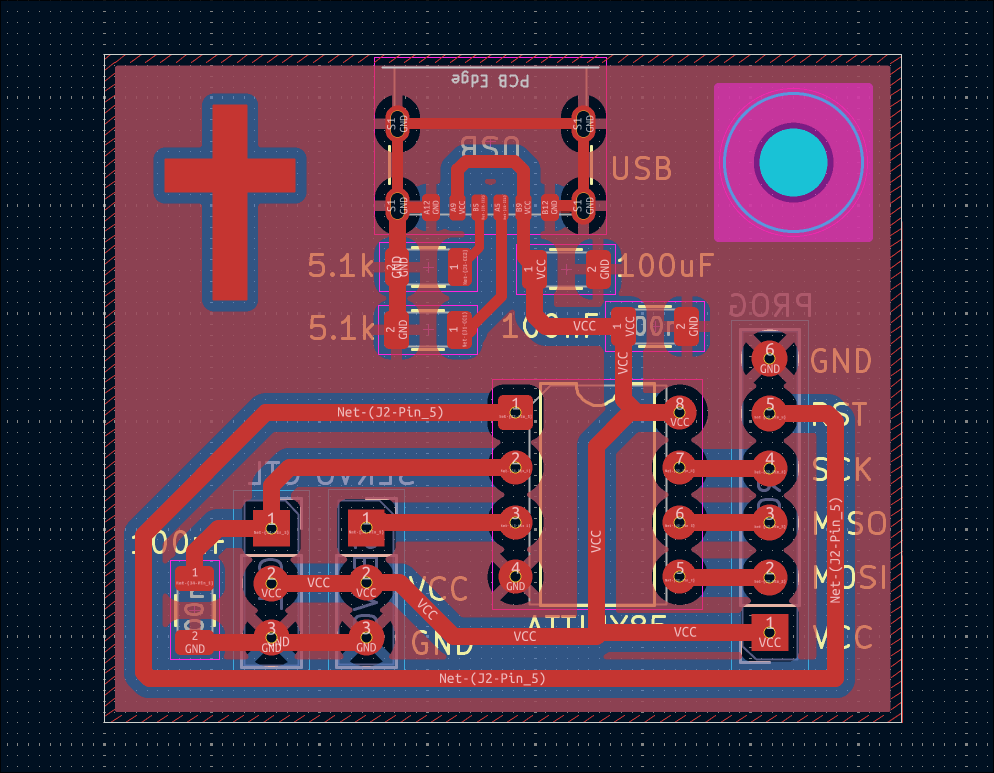
Designed 03007-008 CH32V003A4M6 development board with a PCB board-edge USB connector and a CH340N as a test of both. 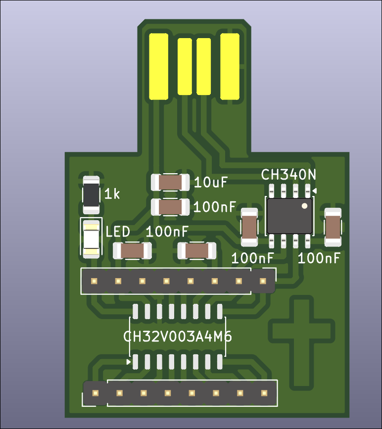
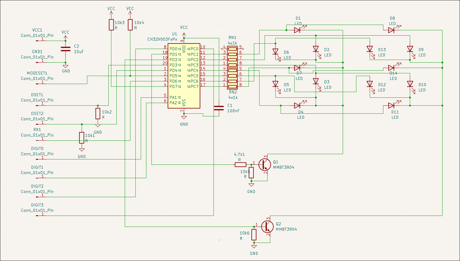
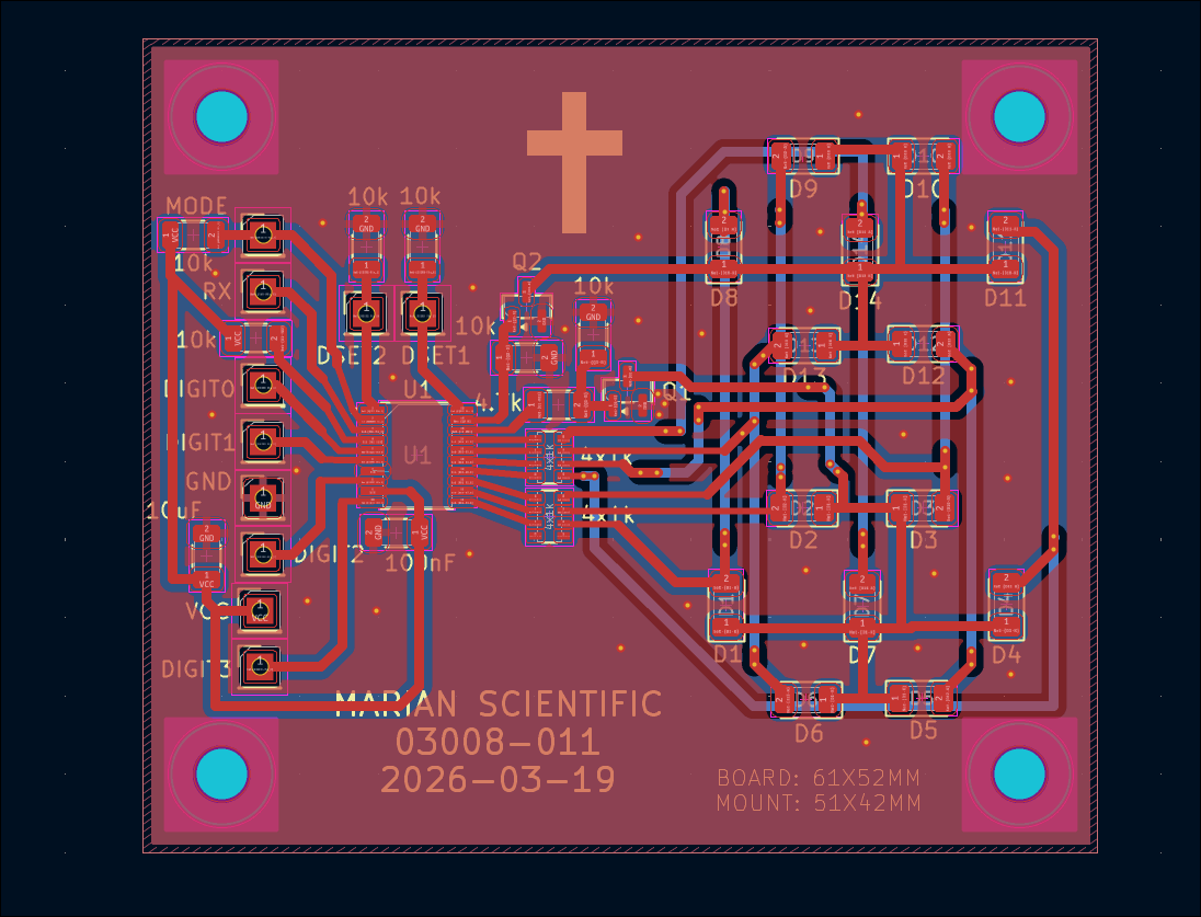
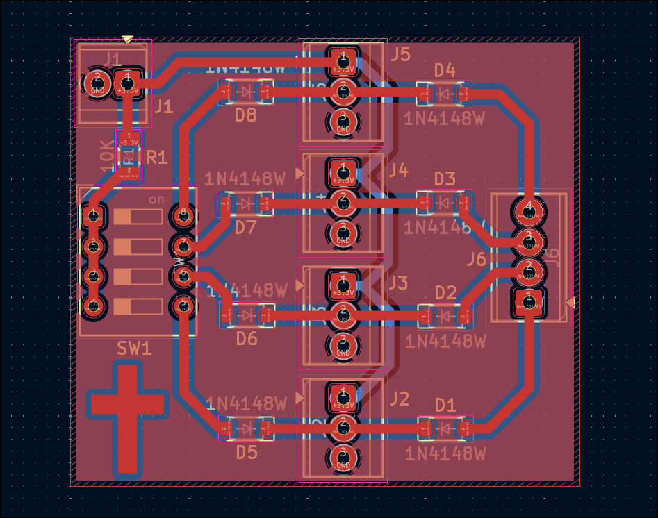
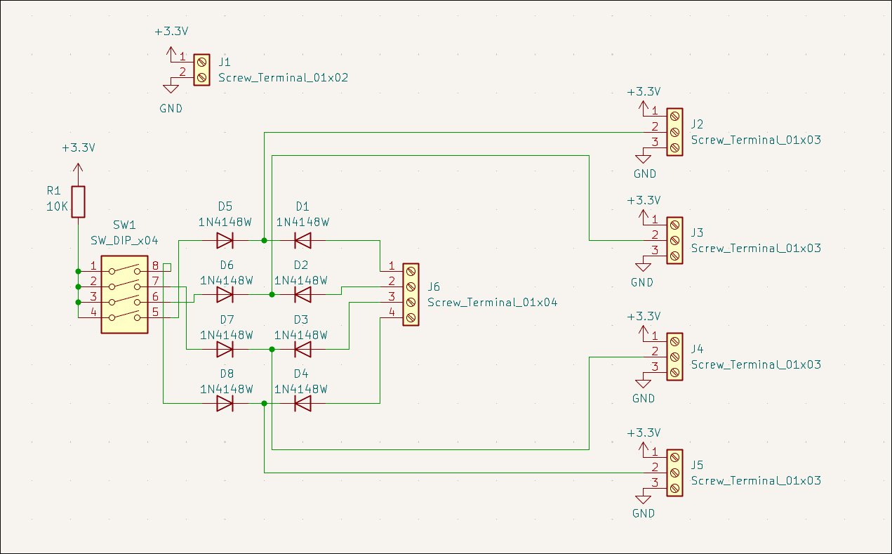
Designed double 7-segment driver and controller circuit (03008-011), can take inputs either from RX or binary digits using MODESET and LATCH pins. The 7 segments are constructed from discrete LEDs, set in slightly opaque epoxy resin. 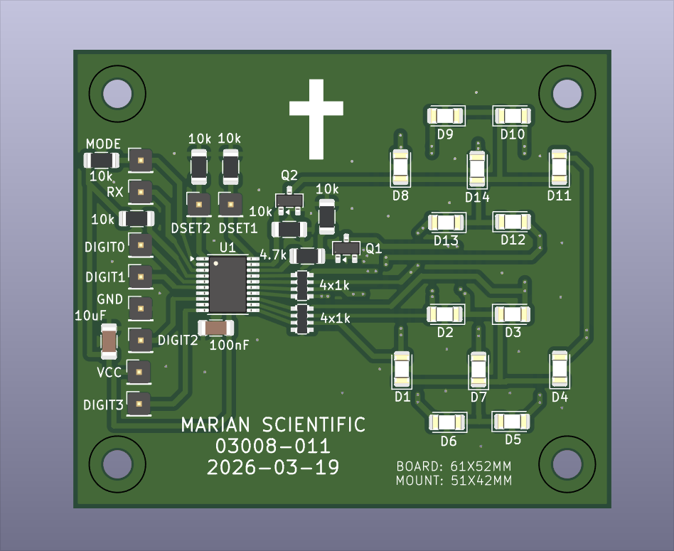
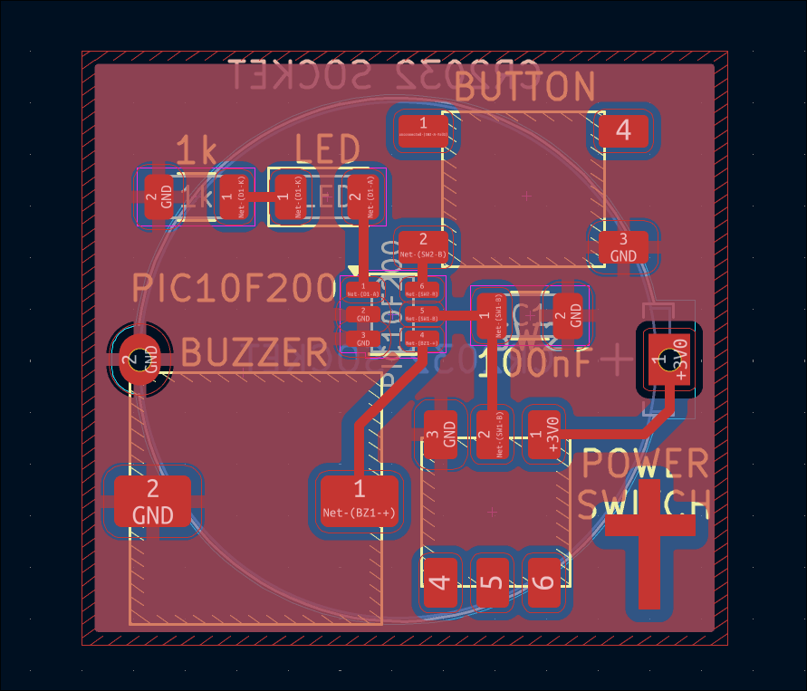
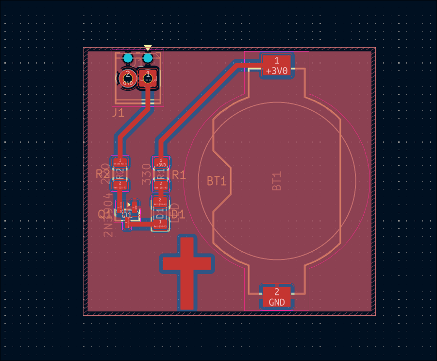
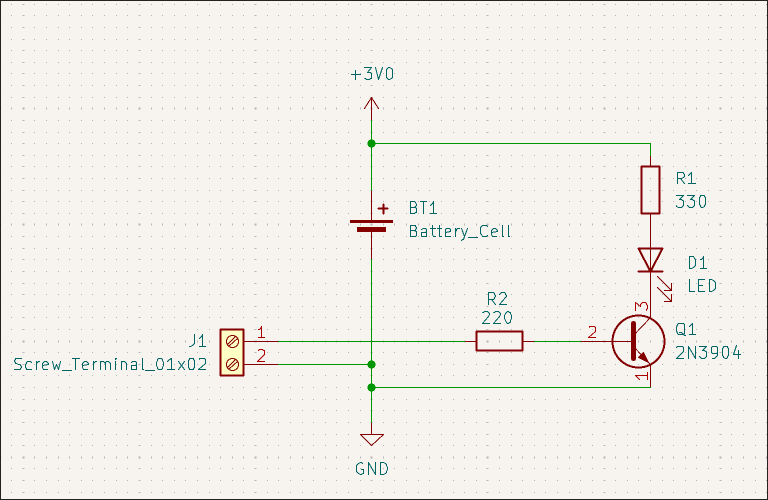
Designed 03014-001 hyper minimalist kitchen timer. Single LED output (flashes number of minutes remaining in quick succession every few seconds), single button input (one push to increment timer, long push to reset, single push to reset on alarm), buzzer, CR2032 battery. 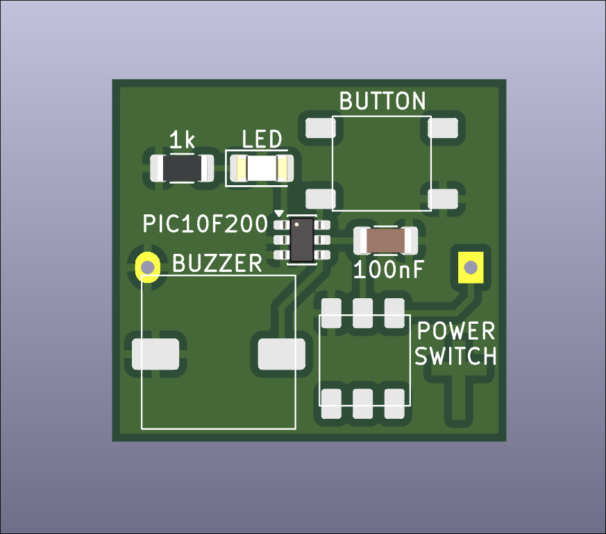
Designed simple 03012-004 PICKIT programmer adapter board to POGO pins for programming/testing of 03012-003 as a test of the process. 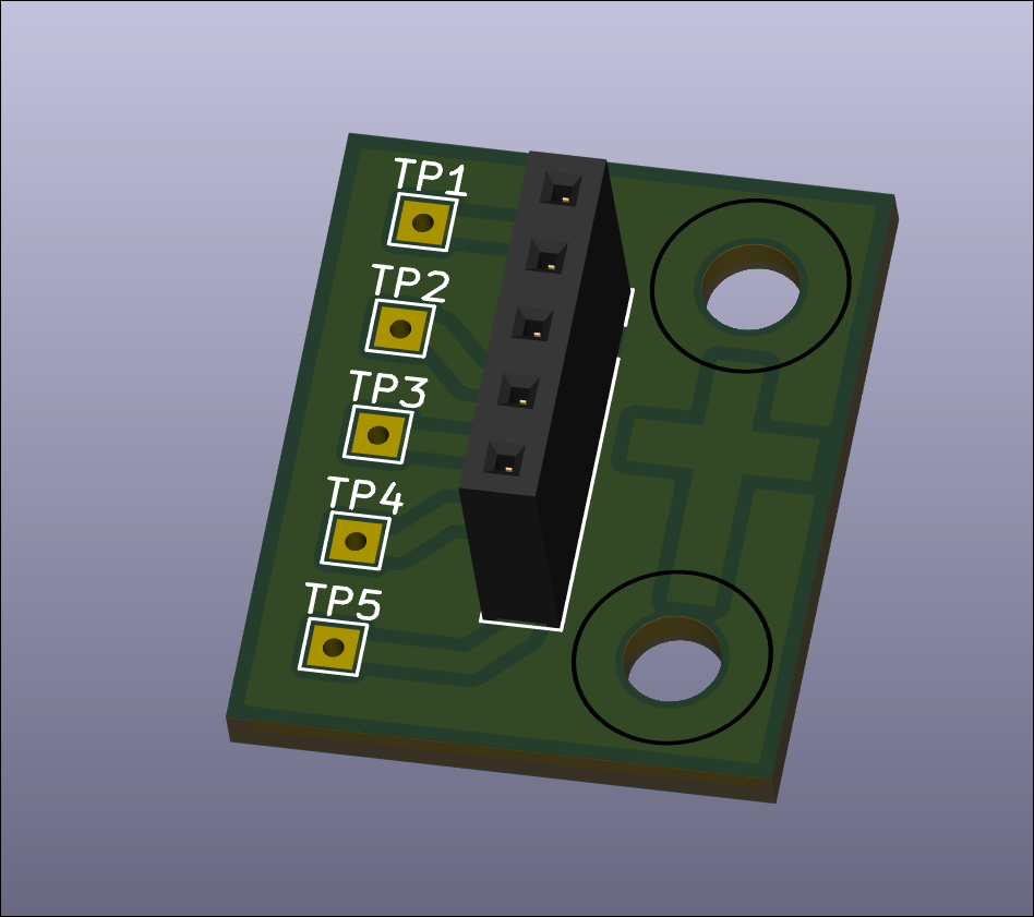
Created GitHub landing page for project with BOM, photos, and links.
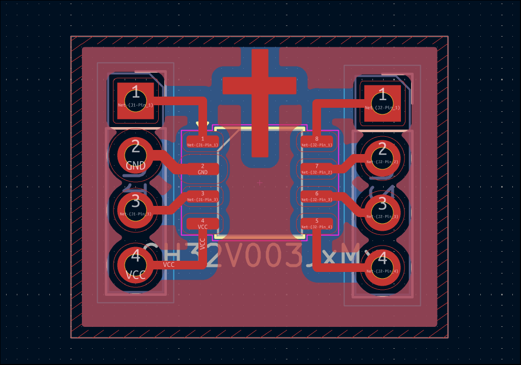
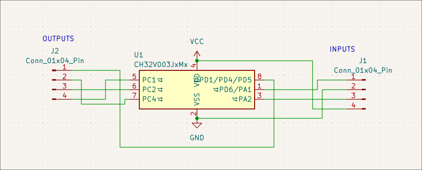
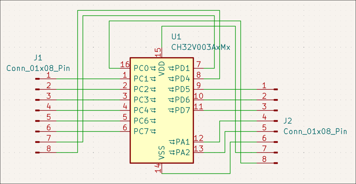
Designed 02005-004 PCB which is seemingly just a SOP8 breakout board, but also with a CH32V003J4M6, you can dedicated 2 pins to power/ground, 2 to input signals A and B, 2 to a mode setting 00/01/10/11, and then get different output signals on the 2 remaining pins: NOT A, NOT B, A OR B, A NOR B, A AND B, A NAND B, A XOR B, A XNOR B. 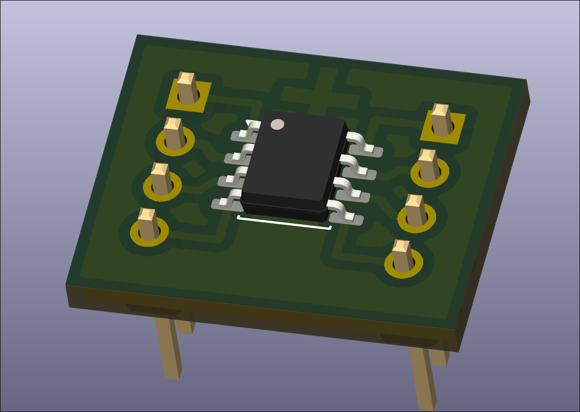
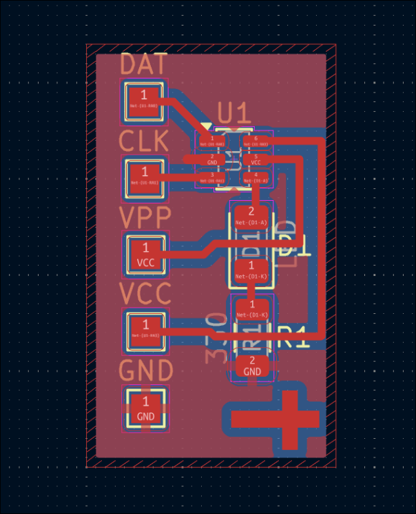
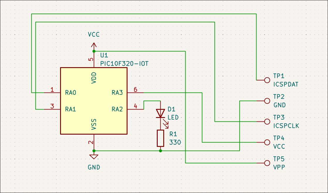
Designed (03012-003) extremely small dev board for PIC10F32* (or 20*) that will be used to test pogo pins, the software toolchain, and use of 1206 components to jump over traces (although that was not required). 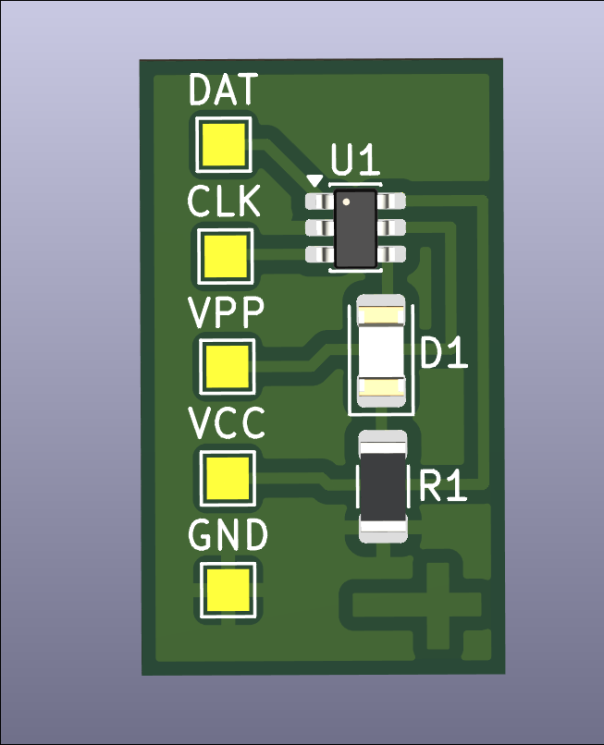
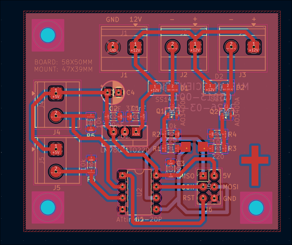
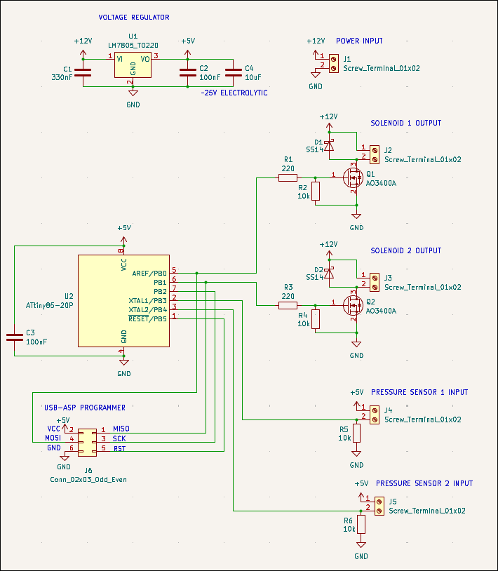
Designed 03013-001 watering can fill board, which will use 2x force-sensitive resistors to determine if 2x watering cans are filled, and use 2x 12V solenoid values to fill them from tap pressure, all controlled by an ATTiny85. 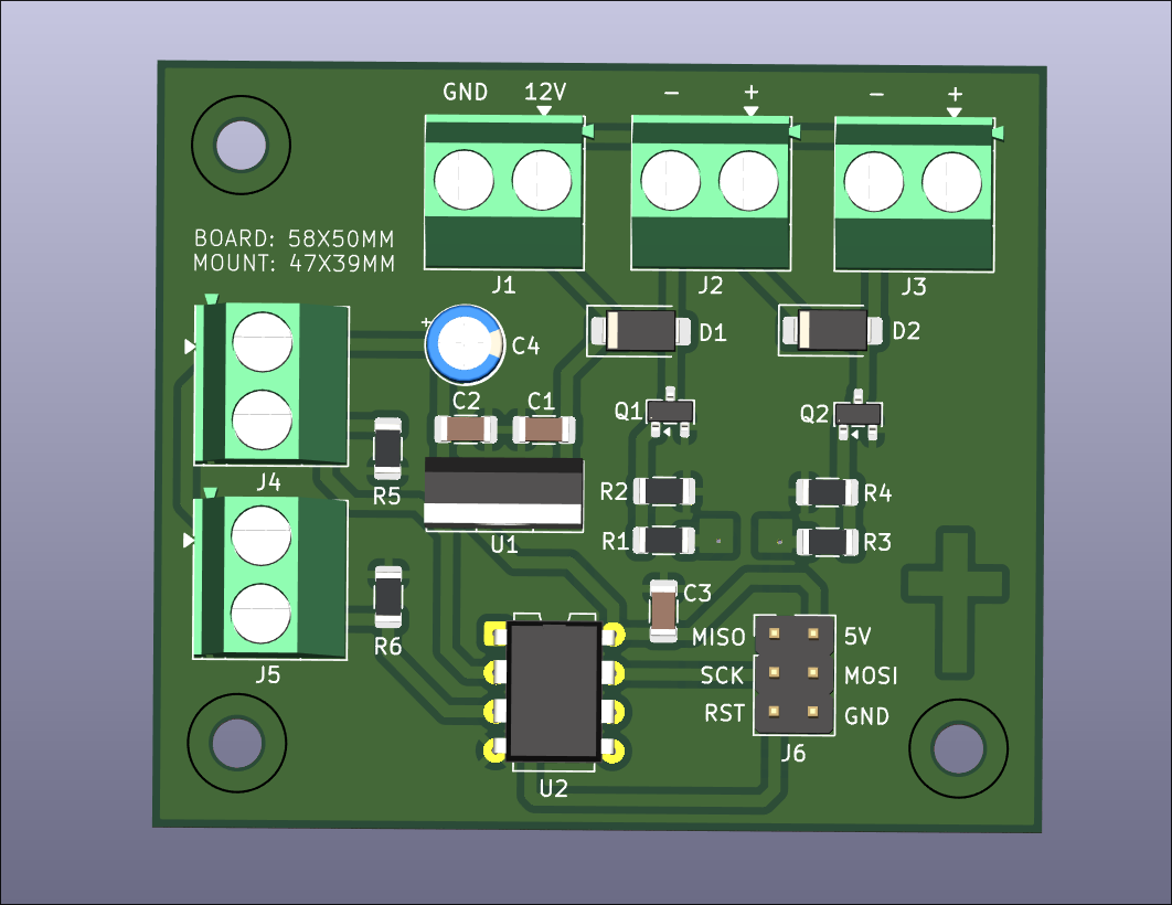
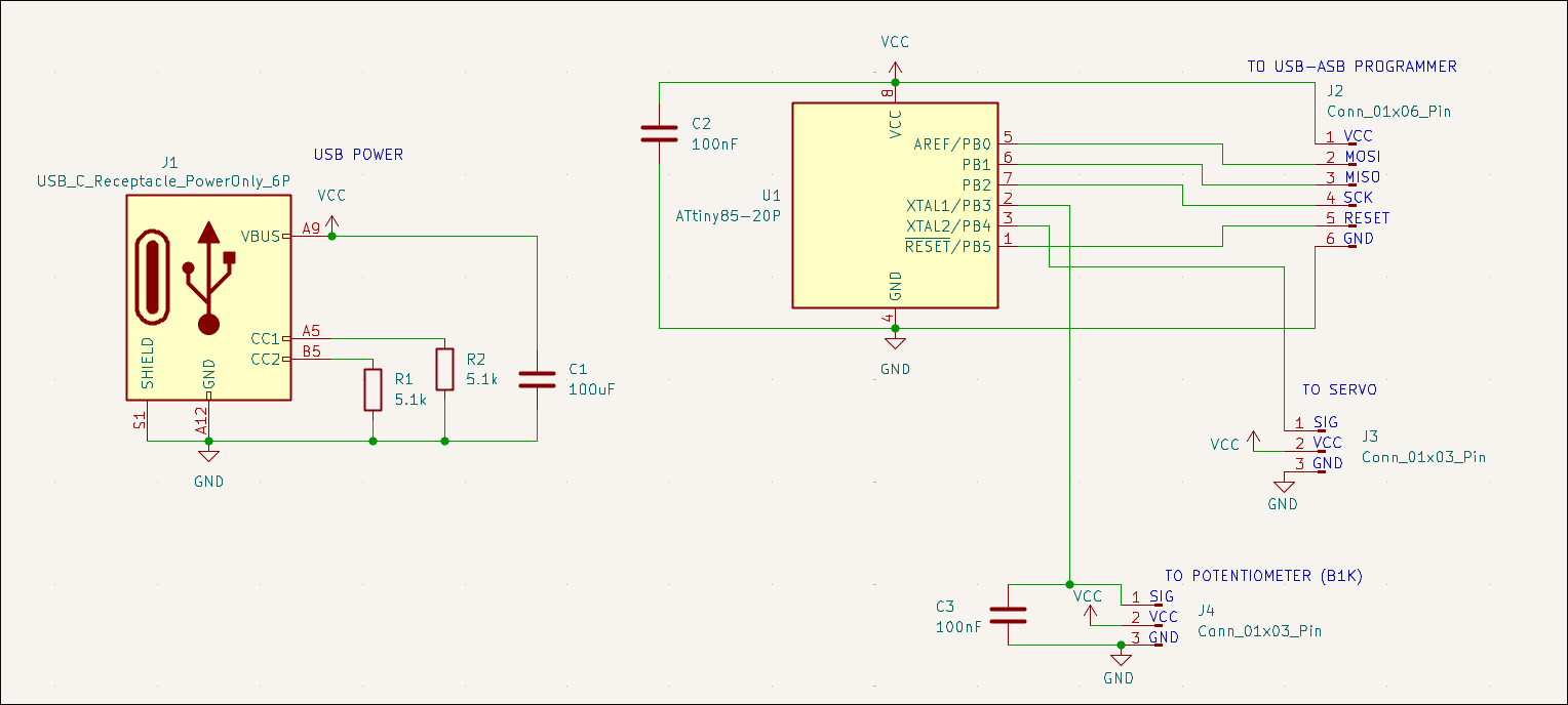
Designed 03012-002 reprogrammable servo motor tester with potentiometer input. 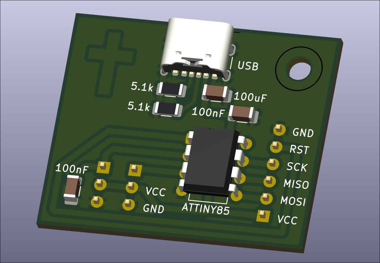
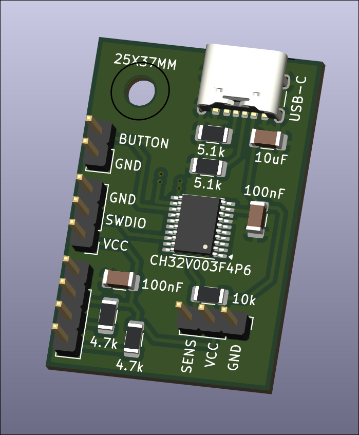
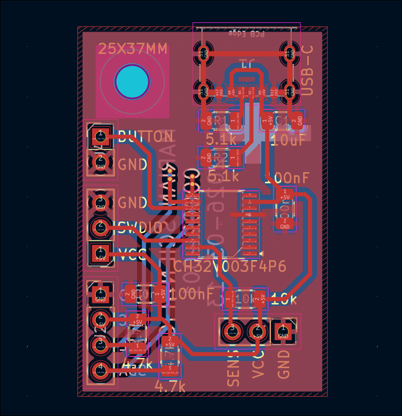
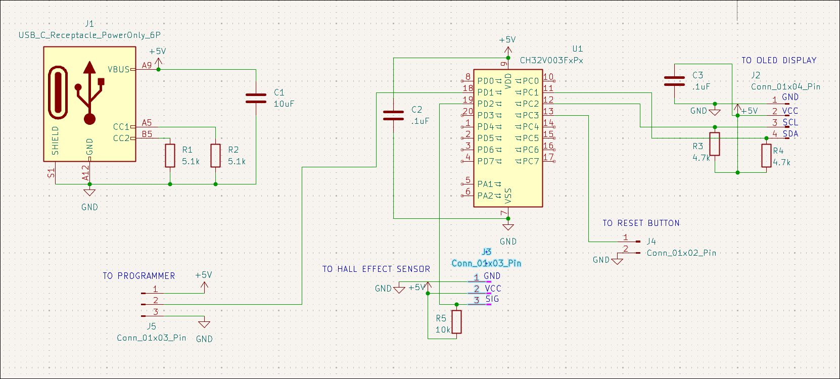
Designed 00002-001 PCB to track rotations of coil winding jig with OLED display output. 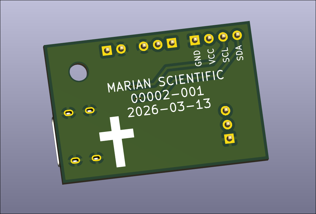
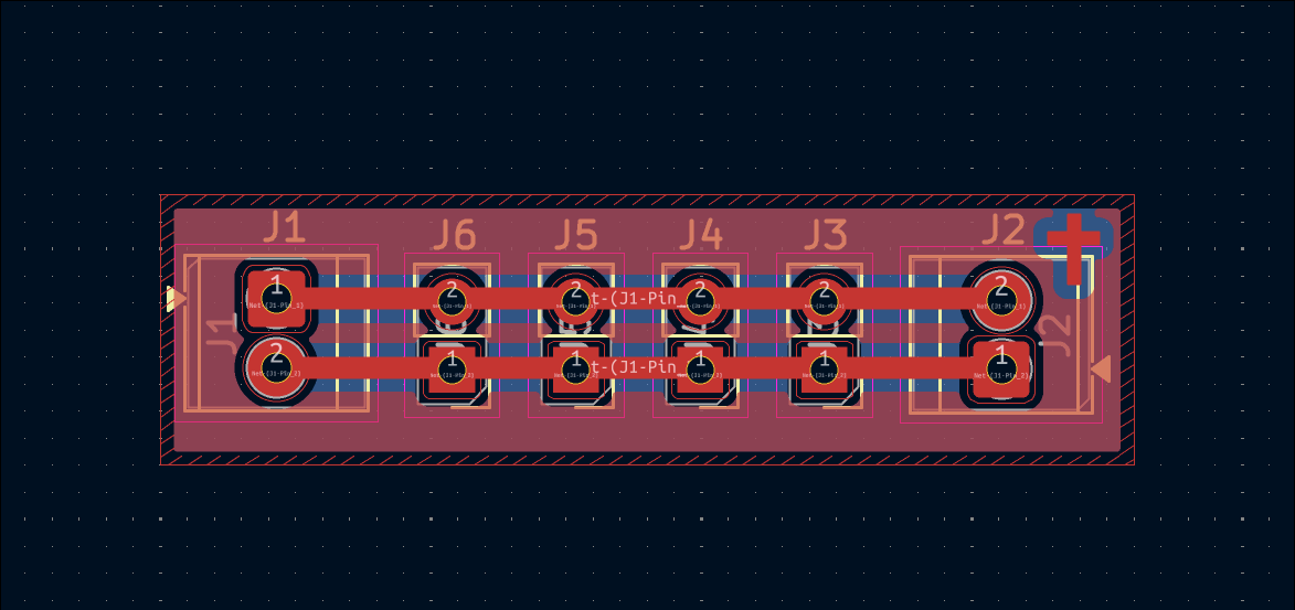
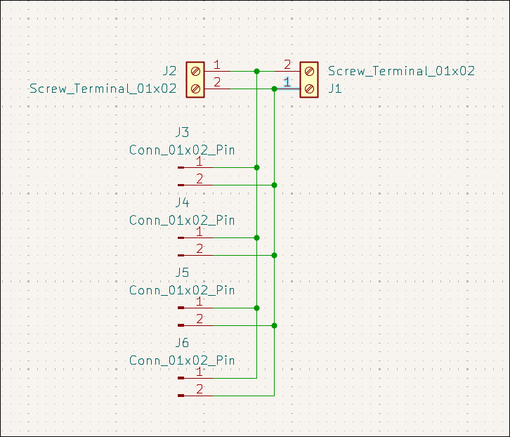
Designed very simple but likely very useful screw terminal / header pin breakout connector board. 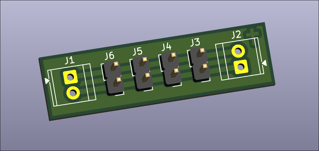
Designed Pi Zero hat for balcony garden pump control. 
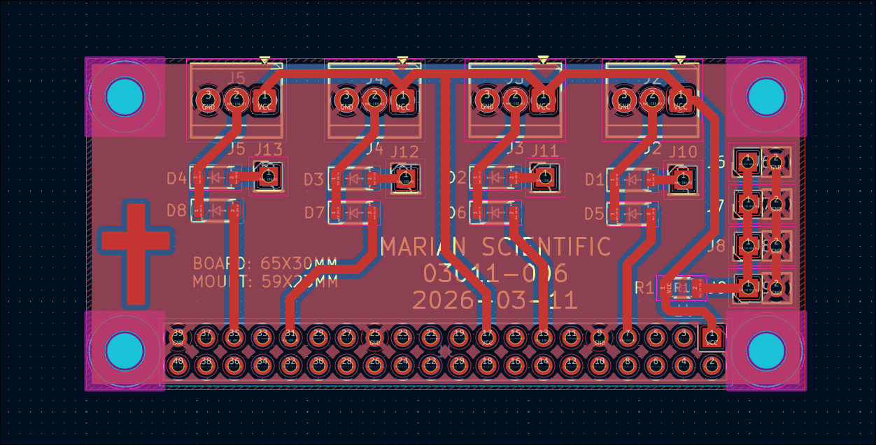
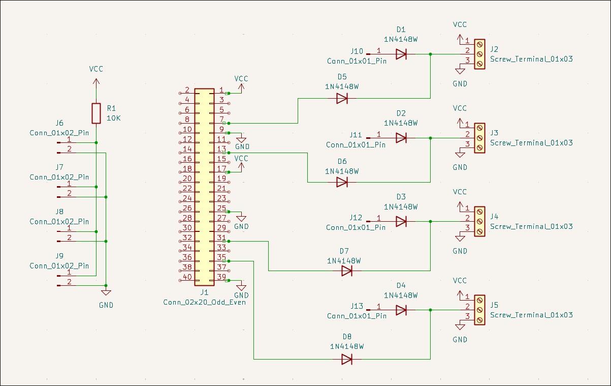
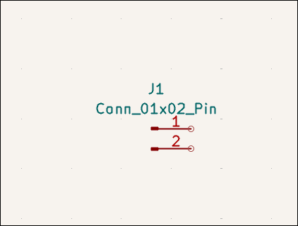
Designed interleaved comb trace board design for both capacitative and resistive moisture detection (03011-005). 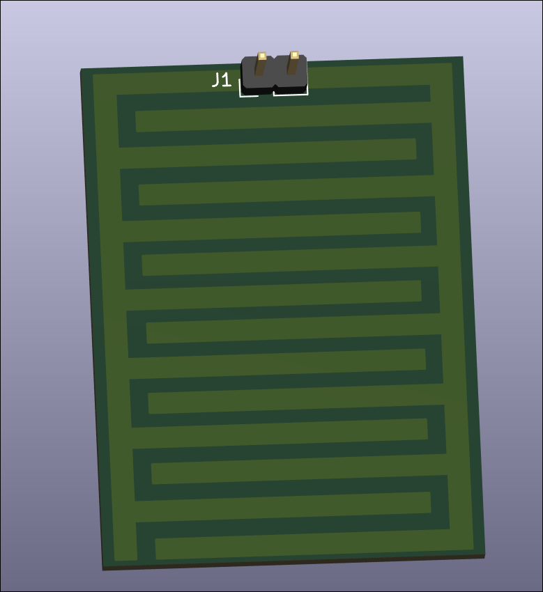

Designed very small capacitative water detection control circuit with an embedded ch32v003 microcontroller for detection, processing, and reporting. This also needs an external capacitor device to make the actual measurements. 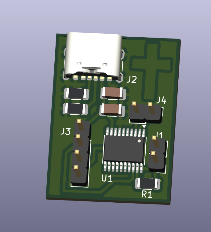
Designed very small resistive water detection control circuit. It needs to be plugged into some expansion board or non-electrolyzable probes. It returns a digital output on a closed circuit. 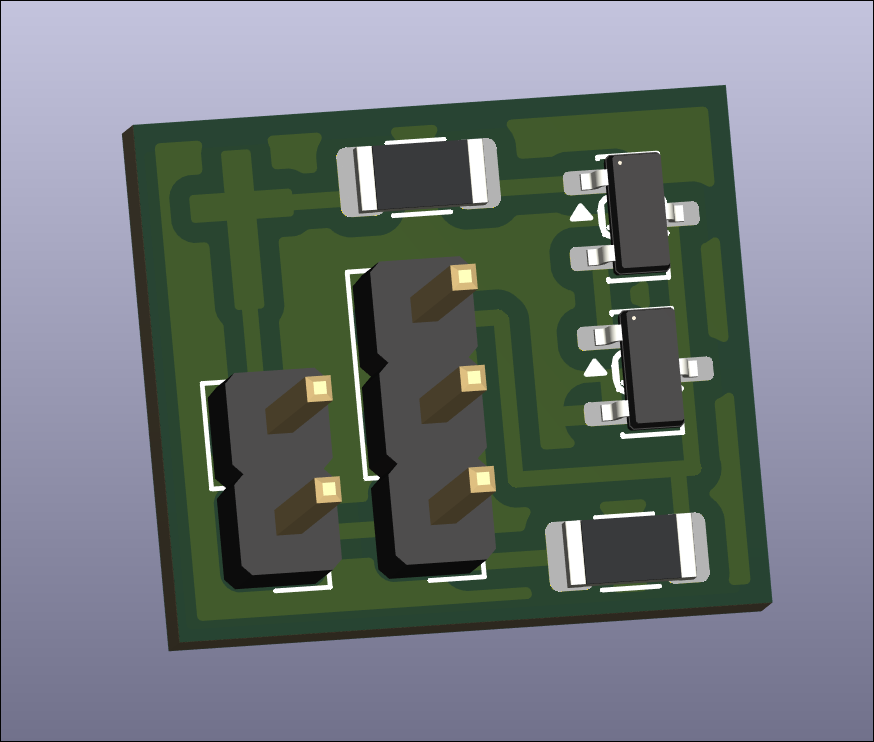
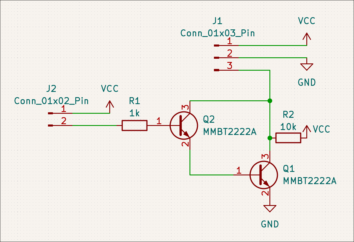
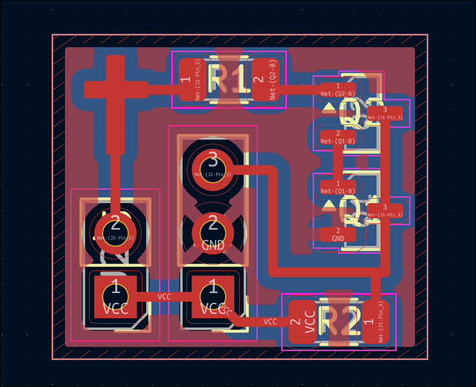
Designed servo control board (03012-001) and ordered on OSHPark. 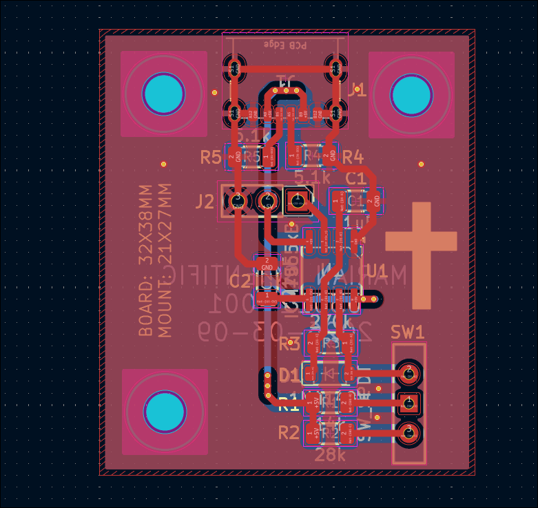
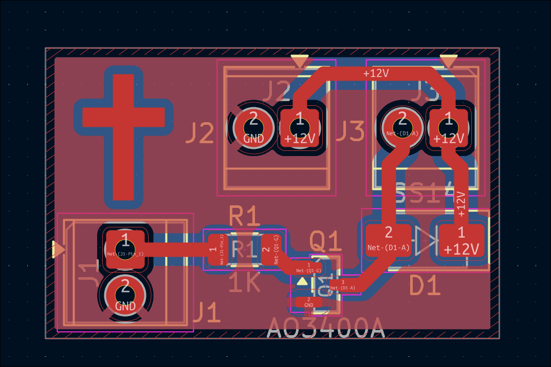
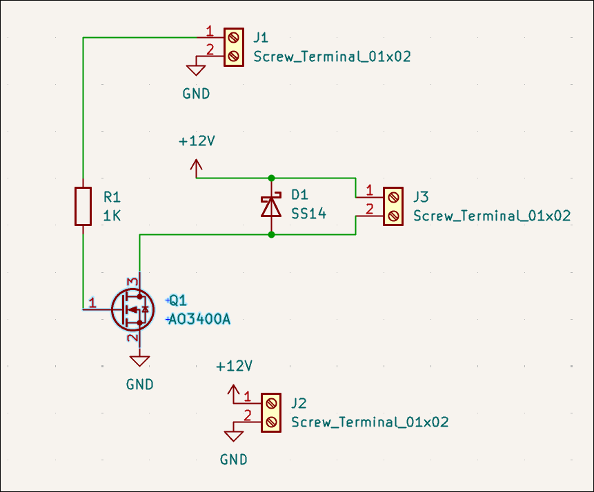
Designed alternative to 12V relay circuit using a single N-channel MOSFET (03011-002). This can be used to drive the water pump from a GPIO pin. 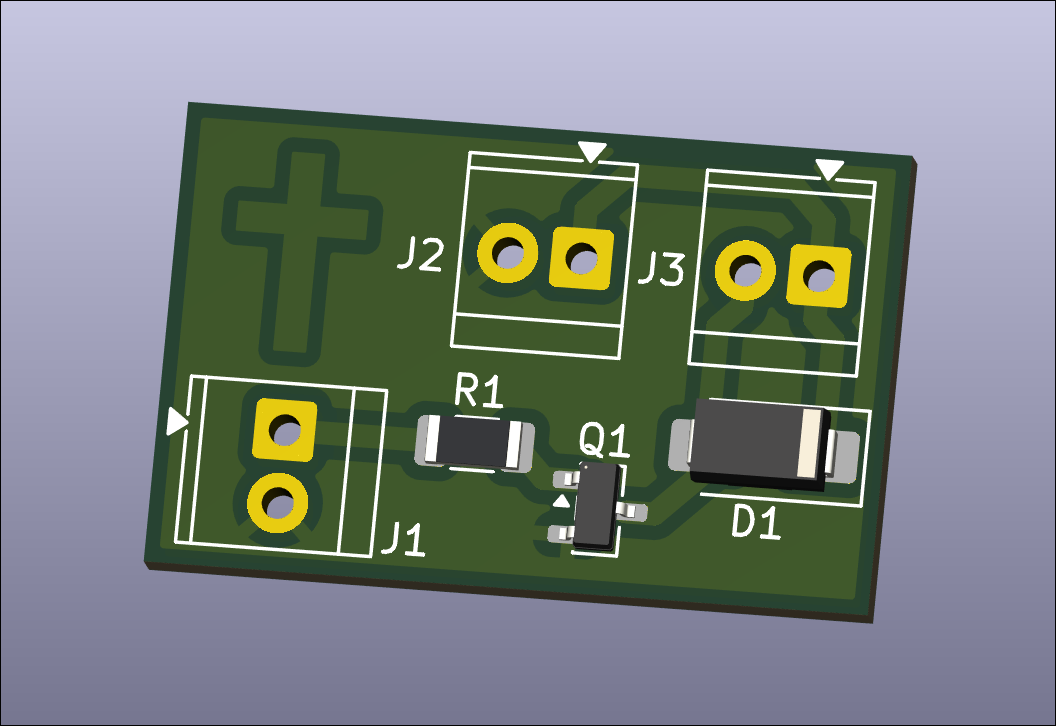
Designed water pump control relay breakout board for balcony garden. This is a nearly 1-1 drop in replacement for what I currently have on a protoboard and used successfully last summer. 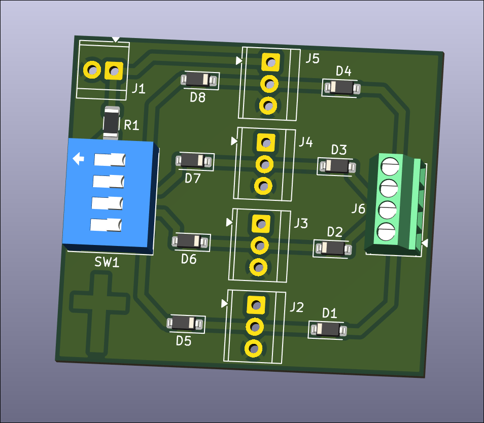
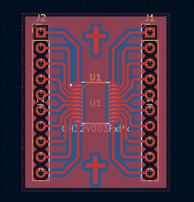
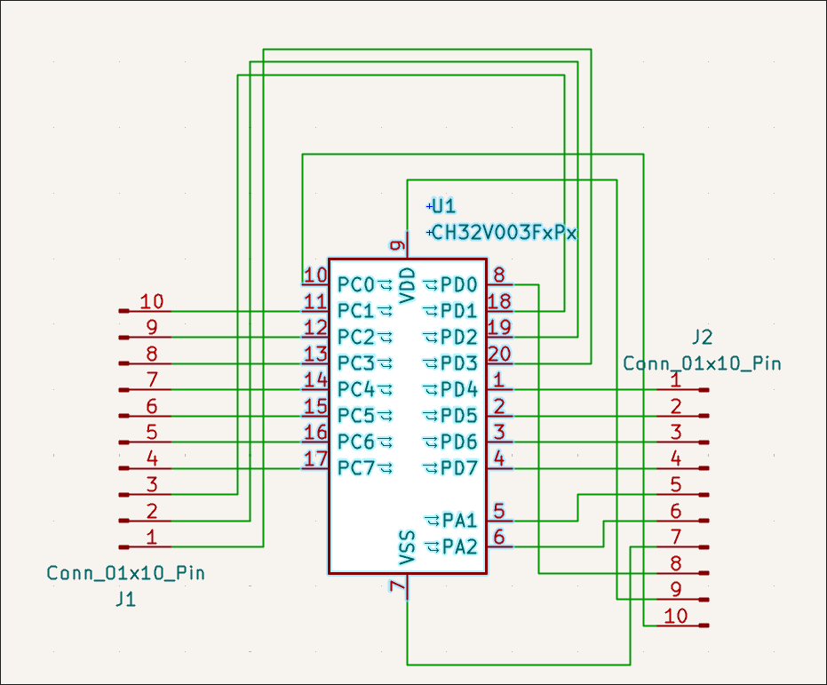
Designed CH32V003F4P6 (TSSOP-20) breakout board. 
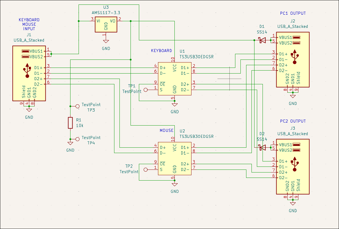
Designed USB mouse & keyboard splitter board (00001-008) for the CNC PC control. Likely will not purchase. 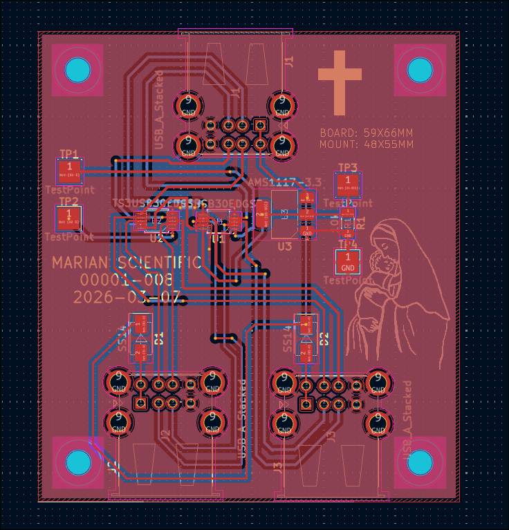
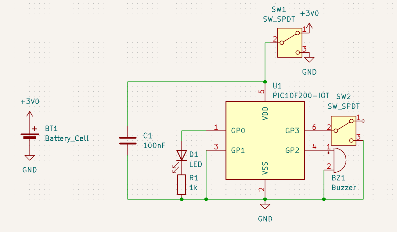
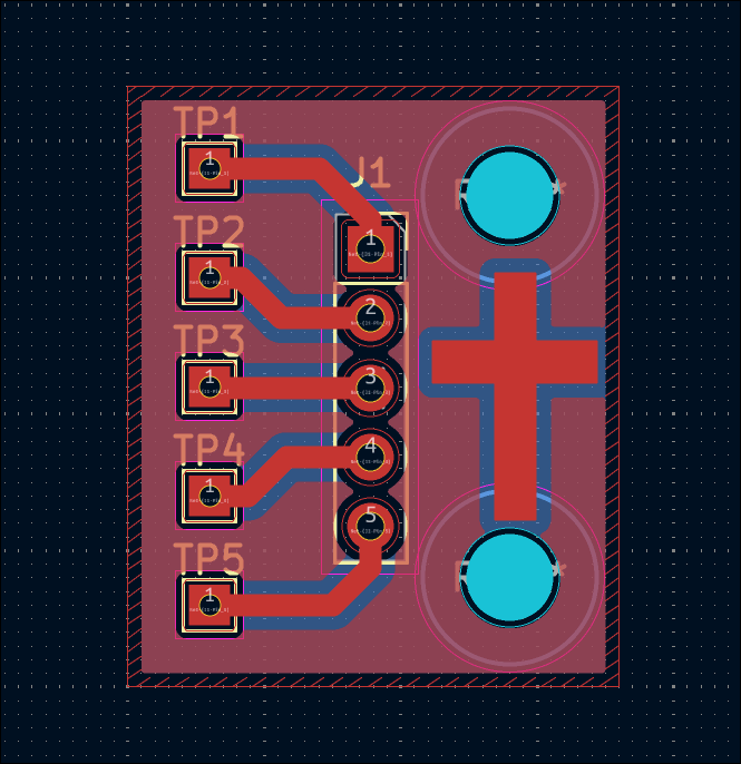
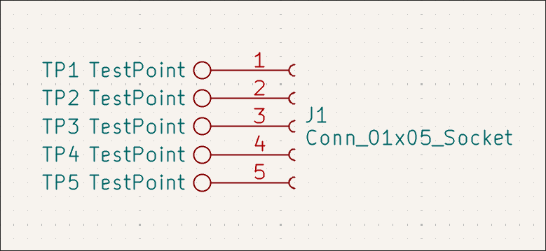
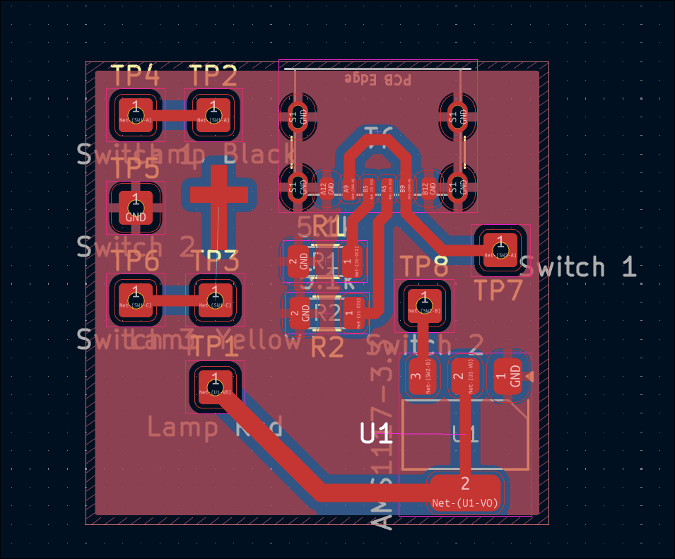
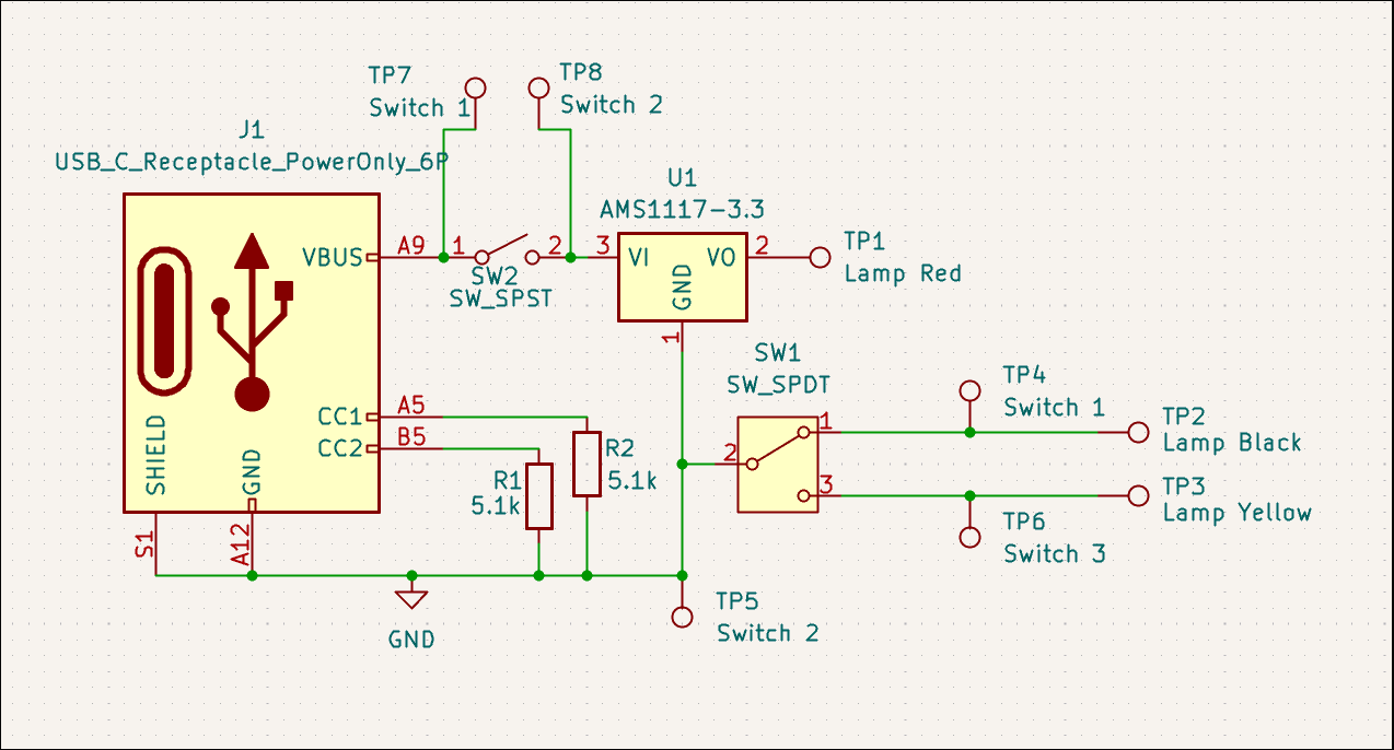
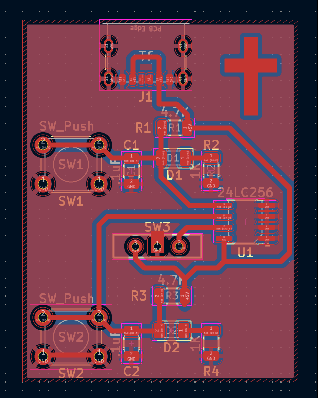
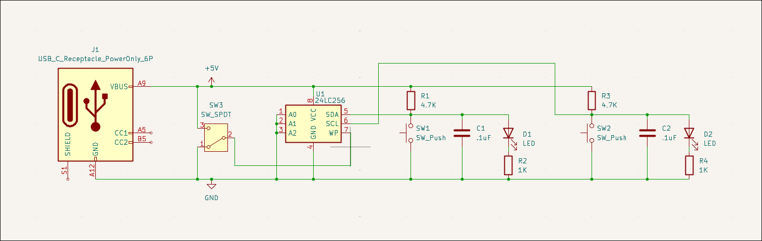
Started first repair/salvage effort for a USB power strip/lamp. The issue was identified to be a shot diode and power IC, which will not be replaced due to prohibitive cost. Instead, the lamp will be salvaged. A board was designed to provide ~3V from USB-C with some toggle switches to control the lamp color and turn on/off the light. All the wires will be soldered to the board at the test points. 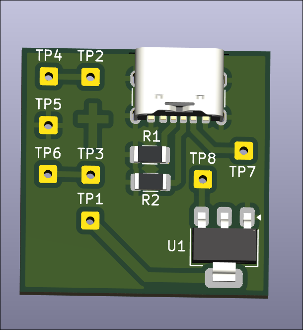
Designed battery-powered continuity checker board (02005-003). 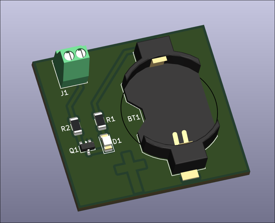
Designed manually read/writable SOIC-8 EEPROM test board (02005-002). 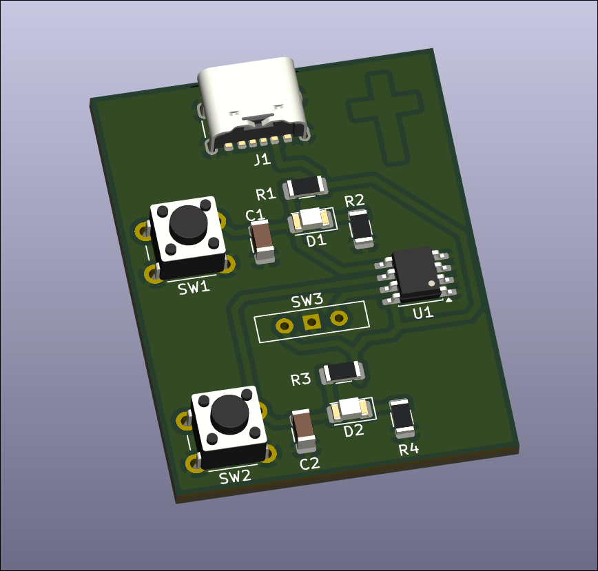
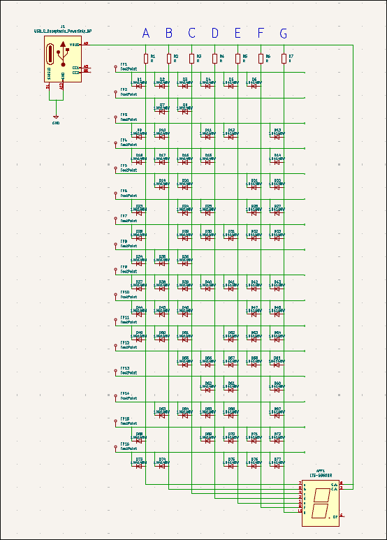
Designed diode ROM 7-segment output board. Did not order at this time due to prohibitive cost ($58/3). 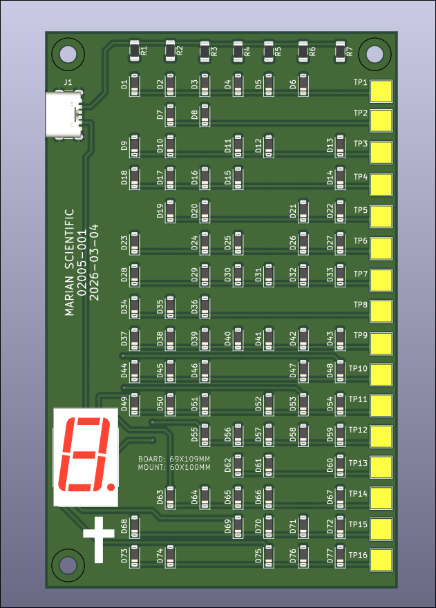
Designed Hall Effect magnetic switch test circuit for future magnet-controlled input sensitivity evaluations. 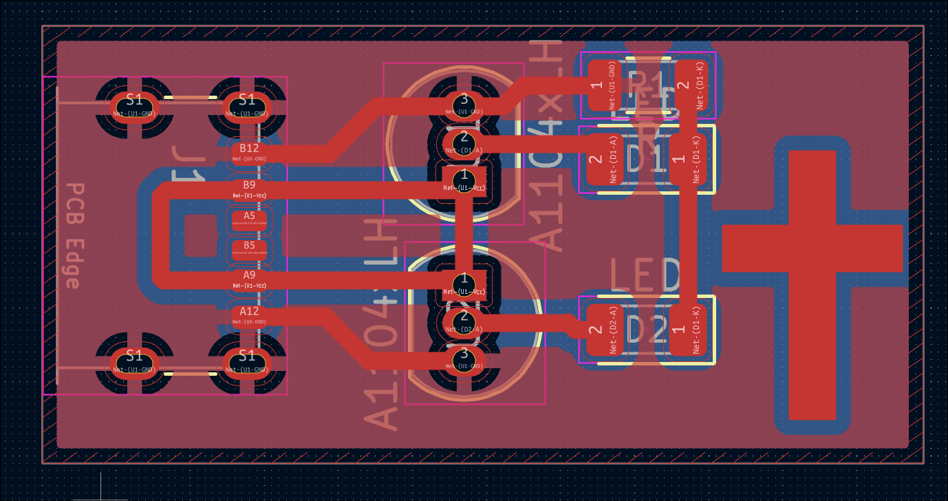
Designed reed switch test circuit for future magnet-controlled input sensitivity evaluations. 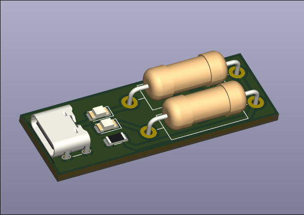
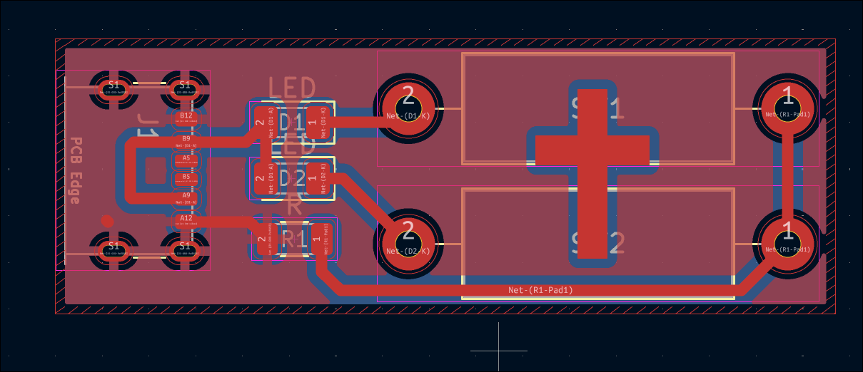
Completed 03007-007 stepper driver PCB design. 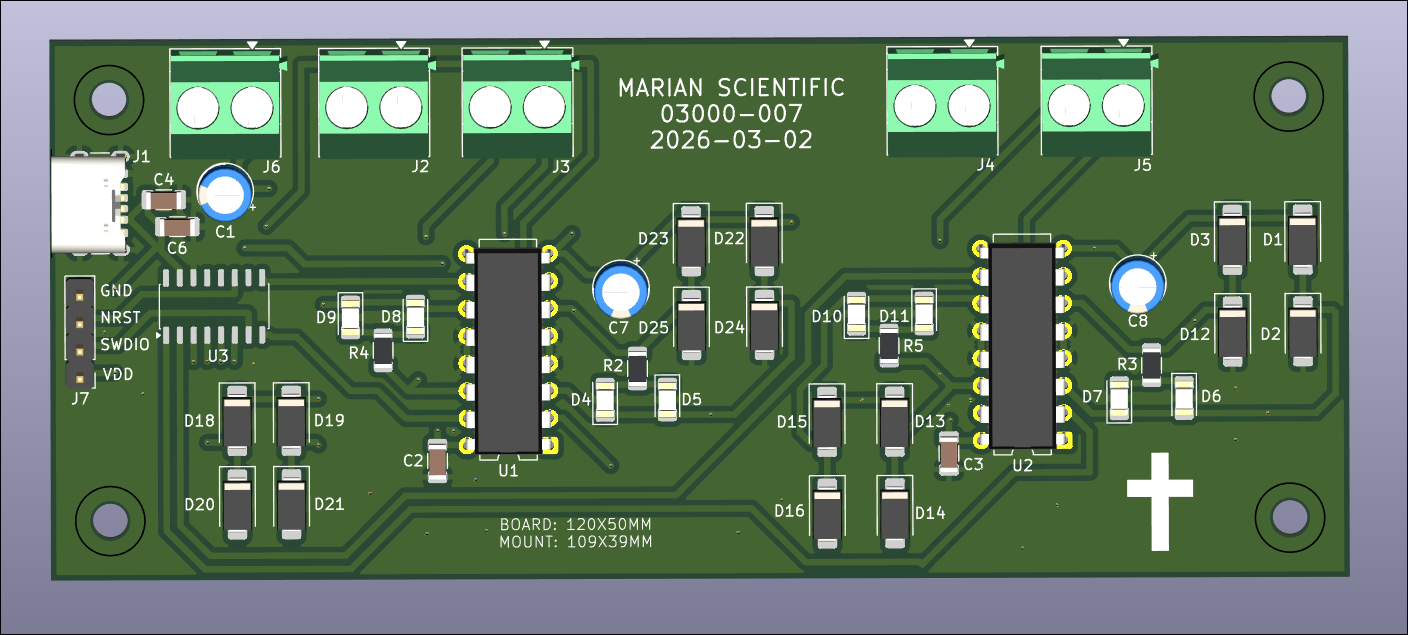
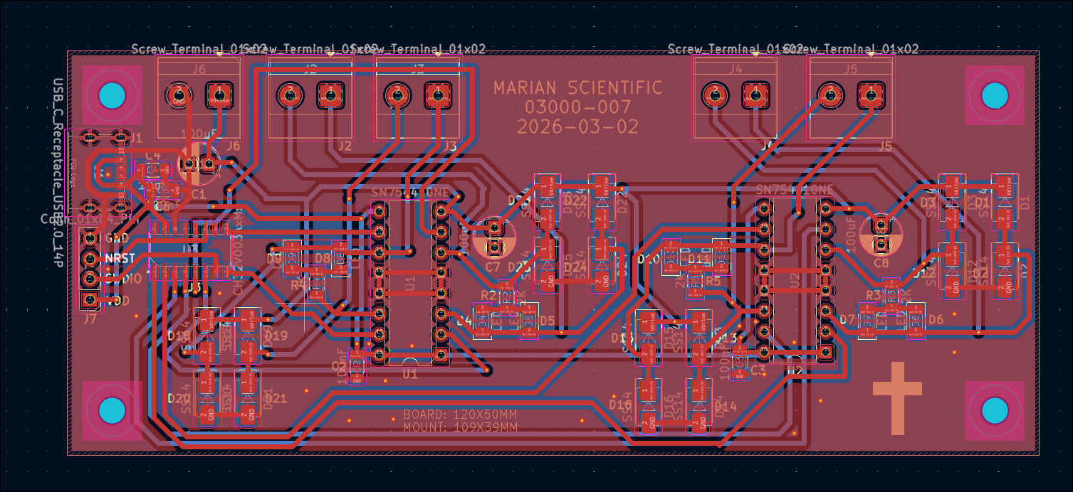
Continued to work on motor driver 03007-007 board. Got roughly 2/3 of the components placed. Will check the circuit and place the rest tomorrow. 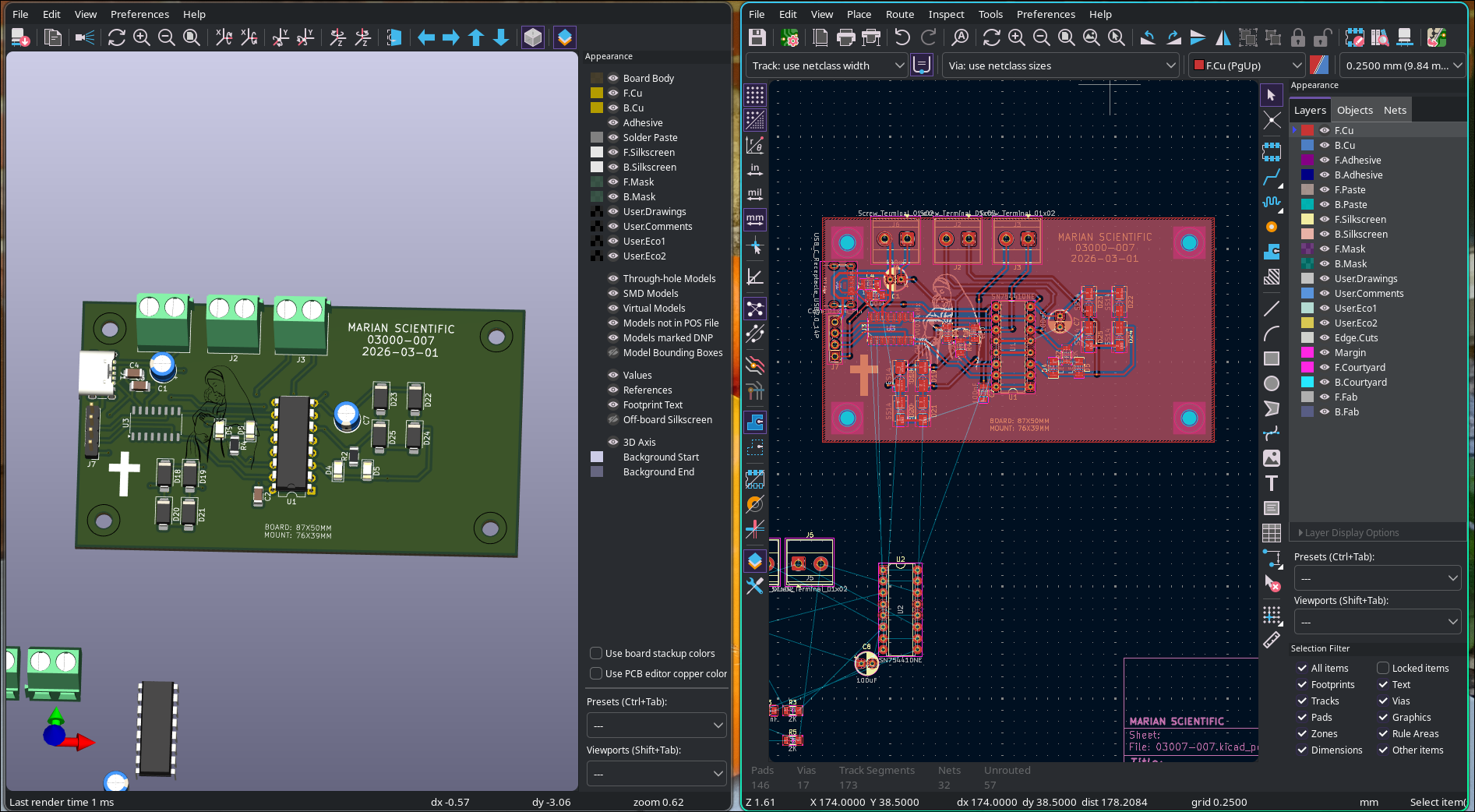
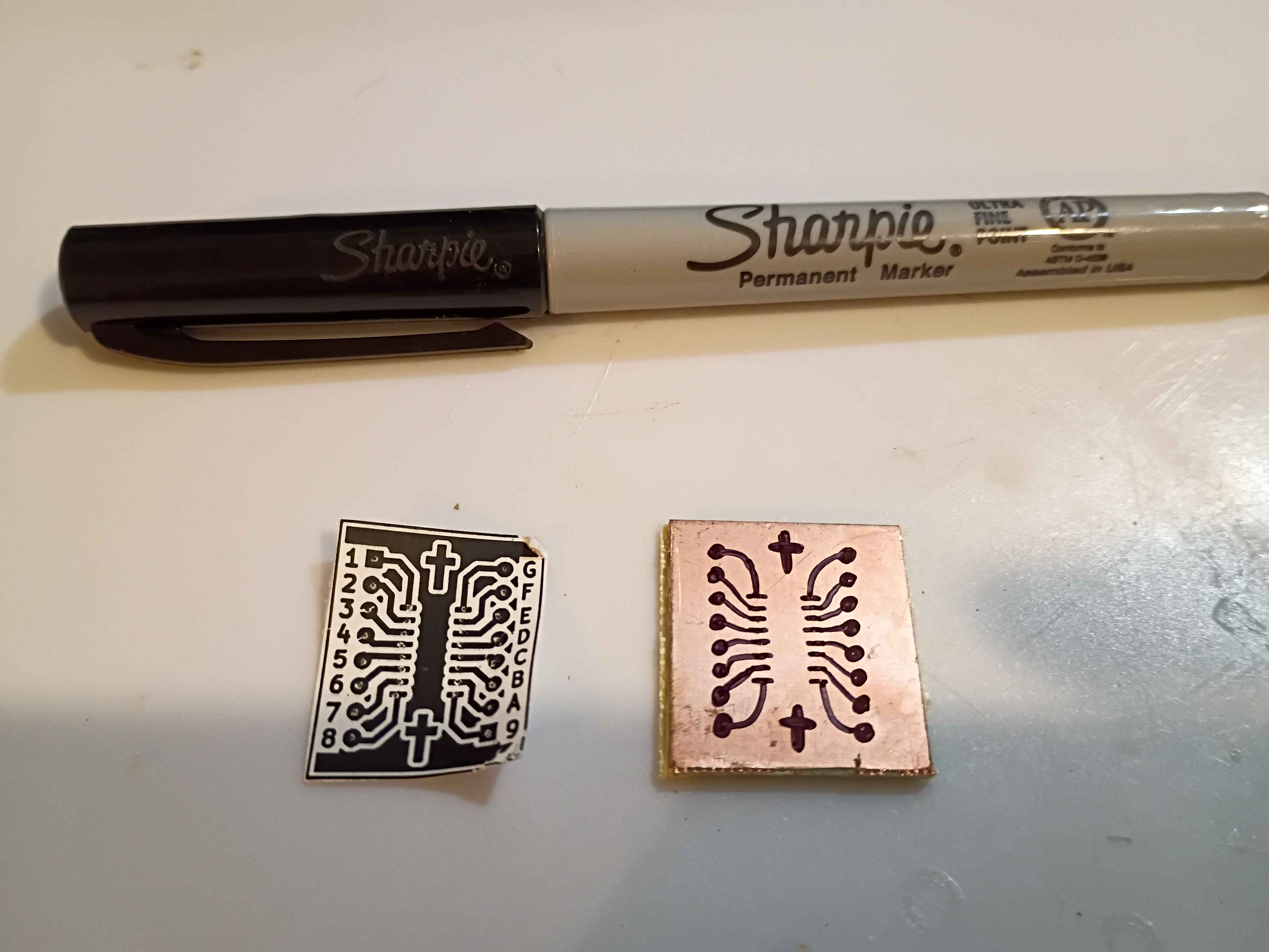
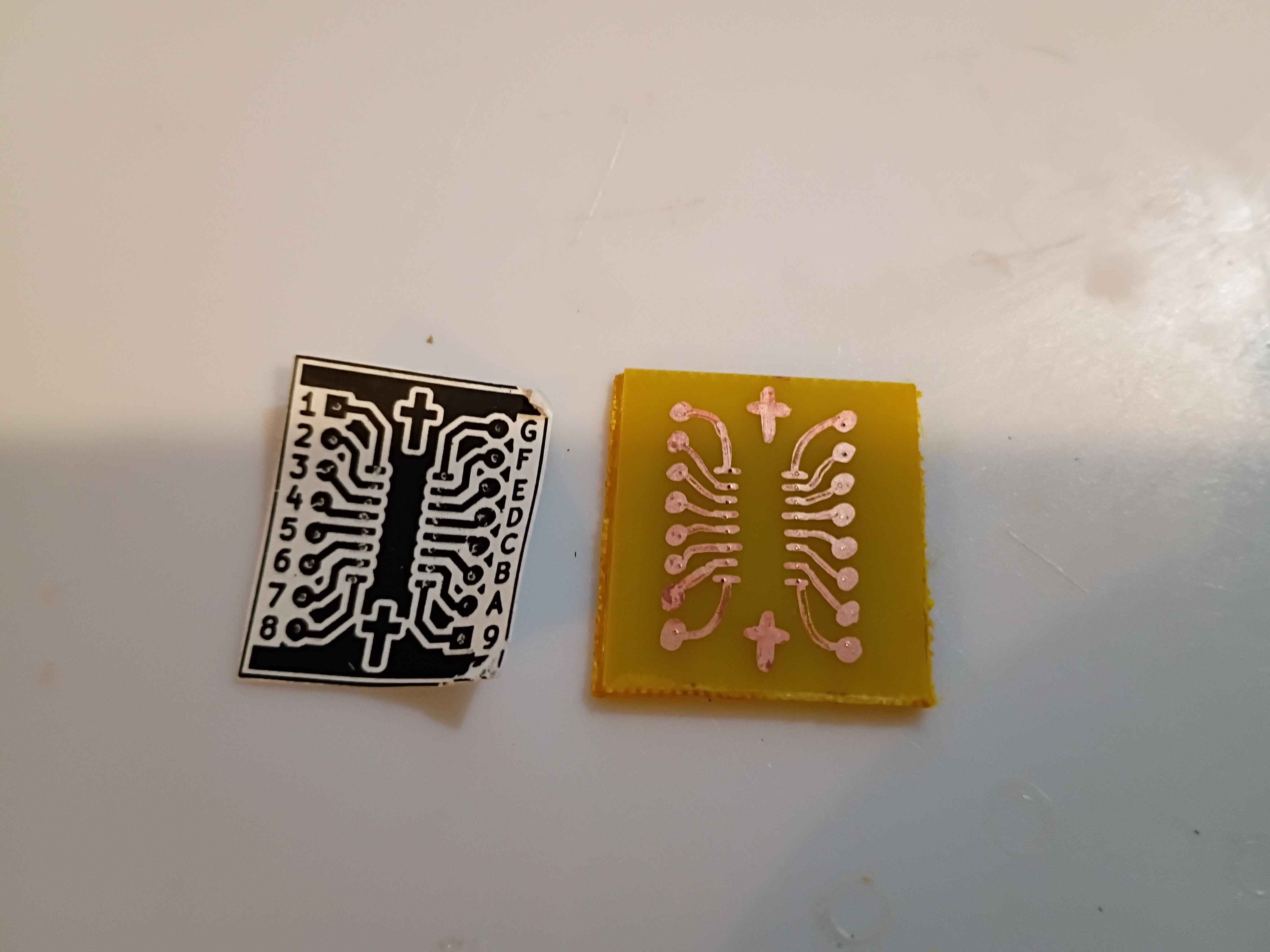
Successfully attempted a new artisanal PCB design transfer method for in-house etching. It involves adhering a non-mirrored image of the traces to the copper face of the copper clad board and pressing in the center of all pads (and corners of all trace line segments) with a thumb tack. Then the paper is removed and the pads and traces are reconstructed by hand using an ultra-fine point sharpie. This has been shown to resist Ferric Chloride etching solution in a previous study. The first attempt was a resounding success, and only took 30 minutes from start to etched board with a very low probability of failure. If the traces are marked incorrectly, they can be wiped away with acetone and easily redrawn. 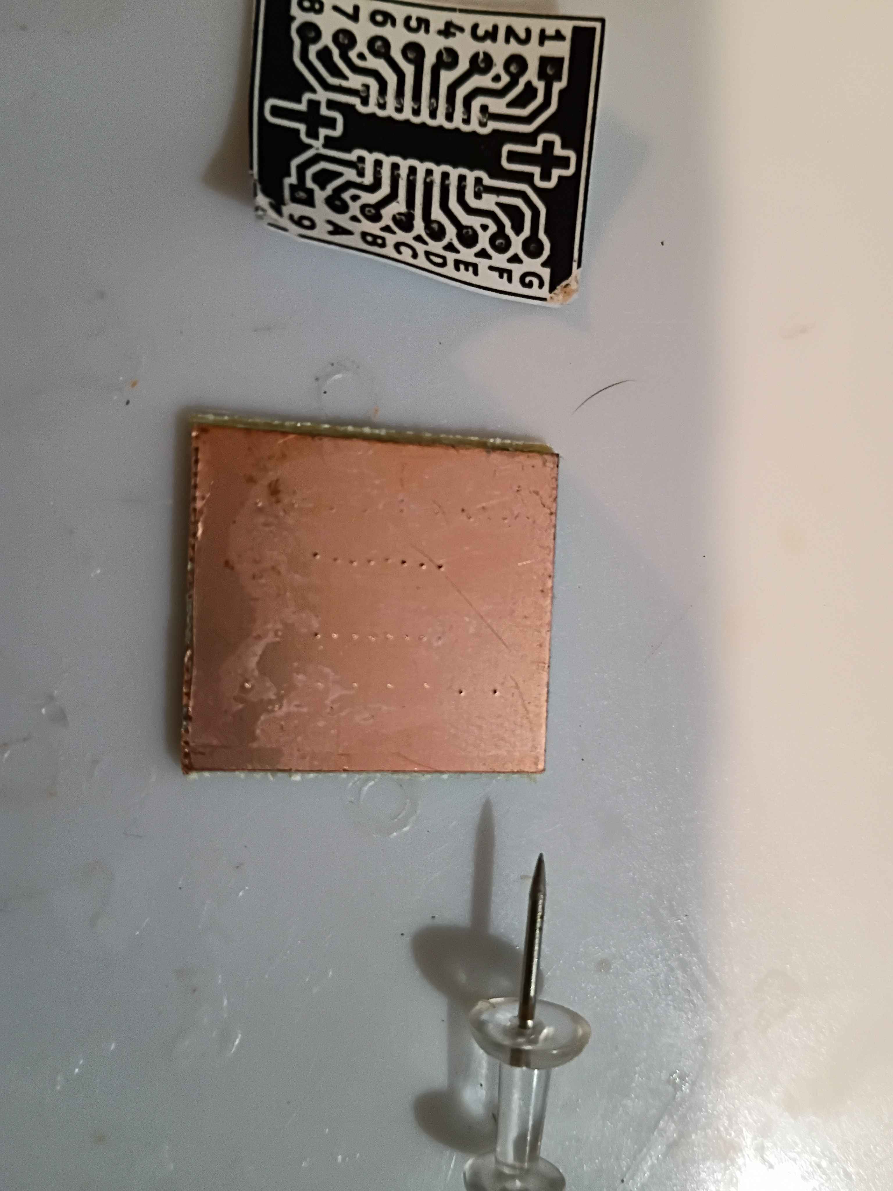
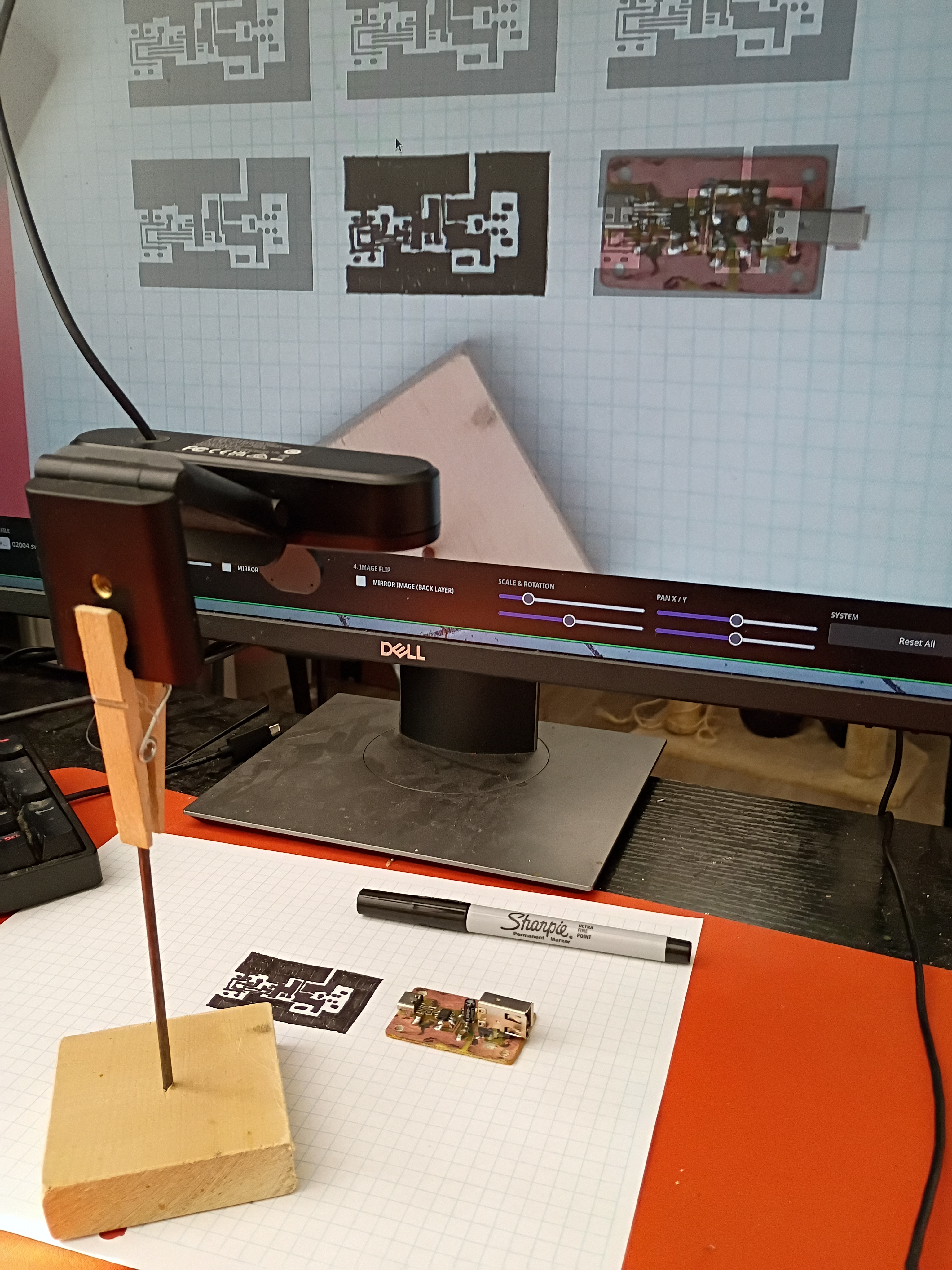
Vibe-coded PCB Camera Lucida utility for PCB tracing. It is available from the http://www.marian-scientific.org/ homepage. It automatically requests the webcam feed and allows the user to upload their mask for tracing. It includes all the basic image transforms at the bottom of the page. It seems to work well. Note that the camera needs to face directly down onto the trace plane, and the user will need to ensure the overlay is scaled properly before starting to trace (maybe put the corner points down and ensure those are spaced appropriately). For the sample trace shown below on graph paper, some of the ink bled between the fine-spaced pads, even with an Ultra Fine Point Sharpie. However, this ink bleeding doesn't happen on a copper surface. 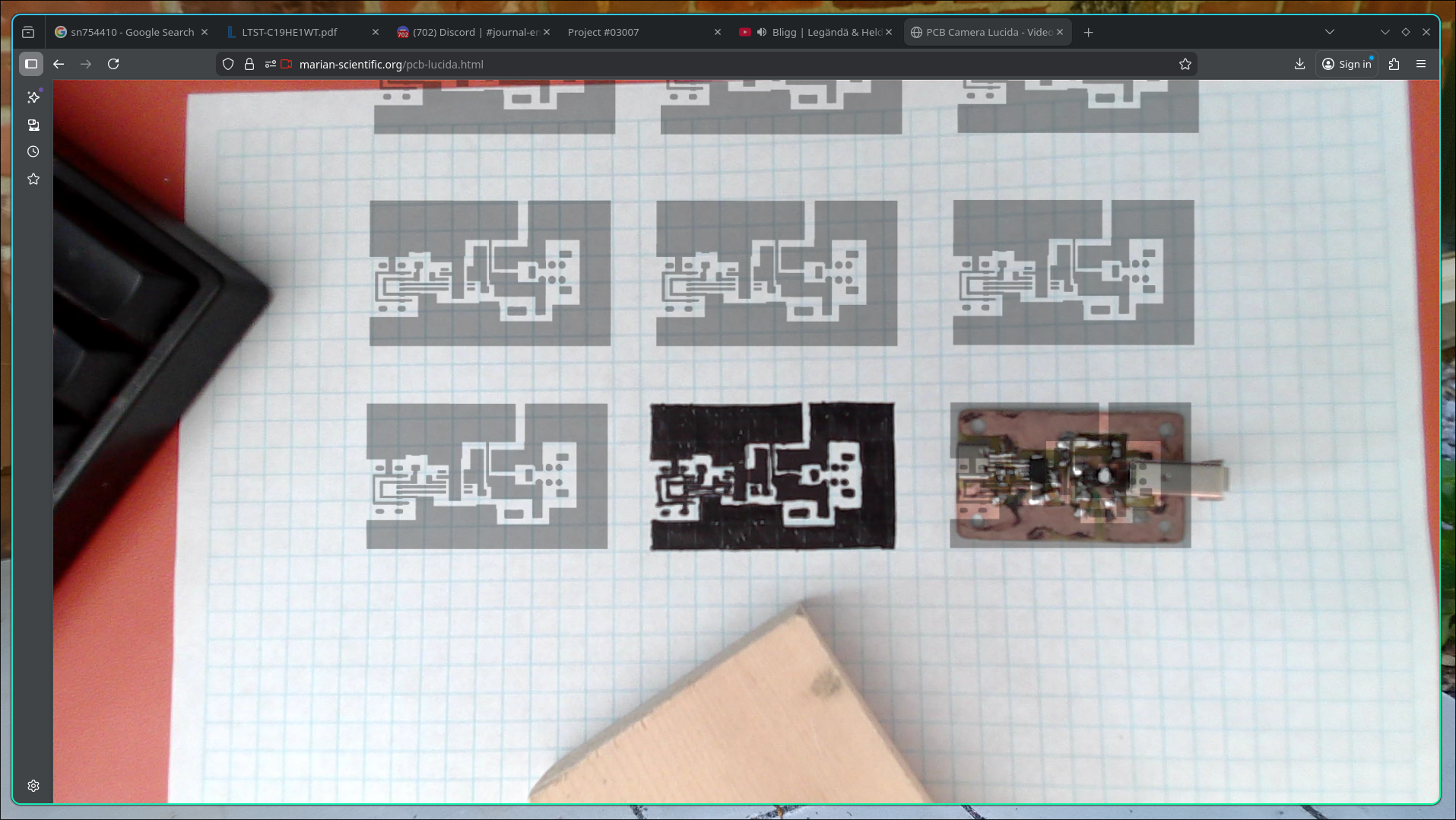
Began schematic design for a CH32V003 stepper motor driver circuit. Still need to add programming header pins to the IC and double-check the circuit. 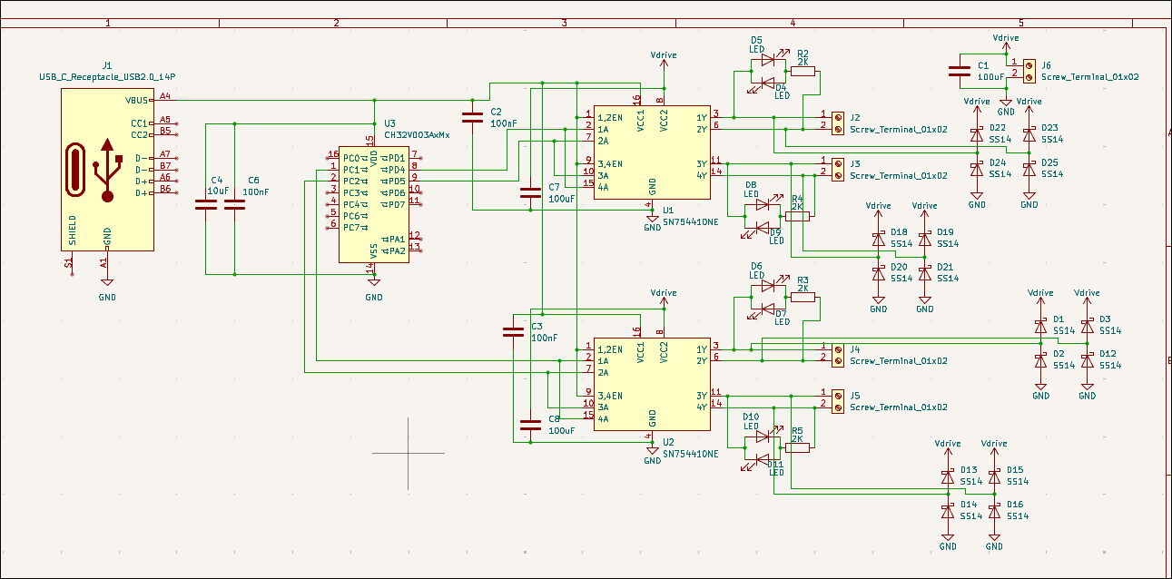
Revised PCB (02004-005-A) with some final lessons learned including test pads, extra exposed copper on the USB-C for solder mounting structure & component labels. 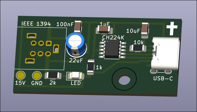
Redrilled and assembled Y motion to eliminate binding. Added Y motion electronics and tested the control software. 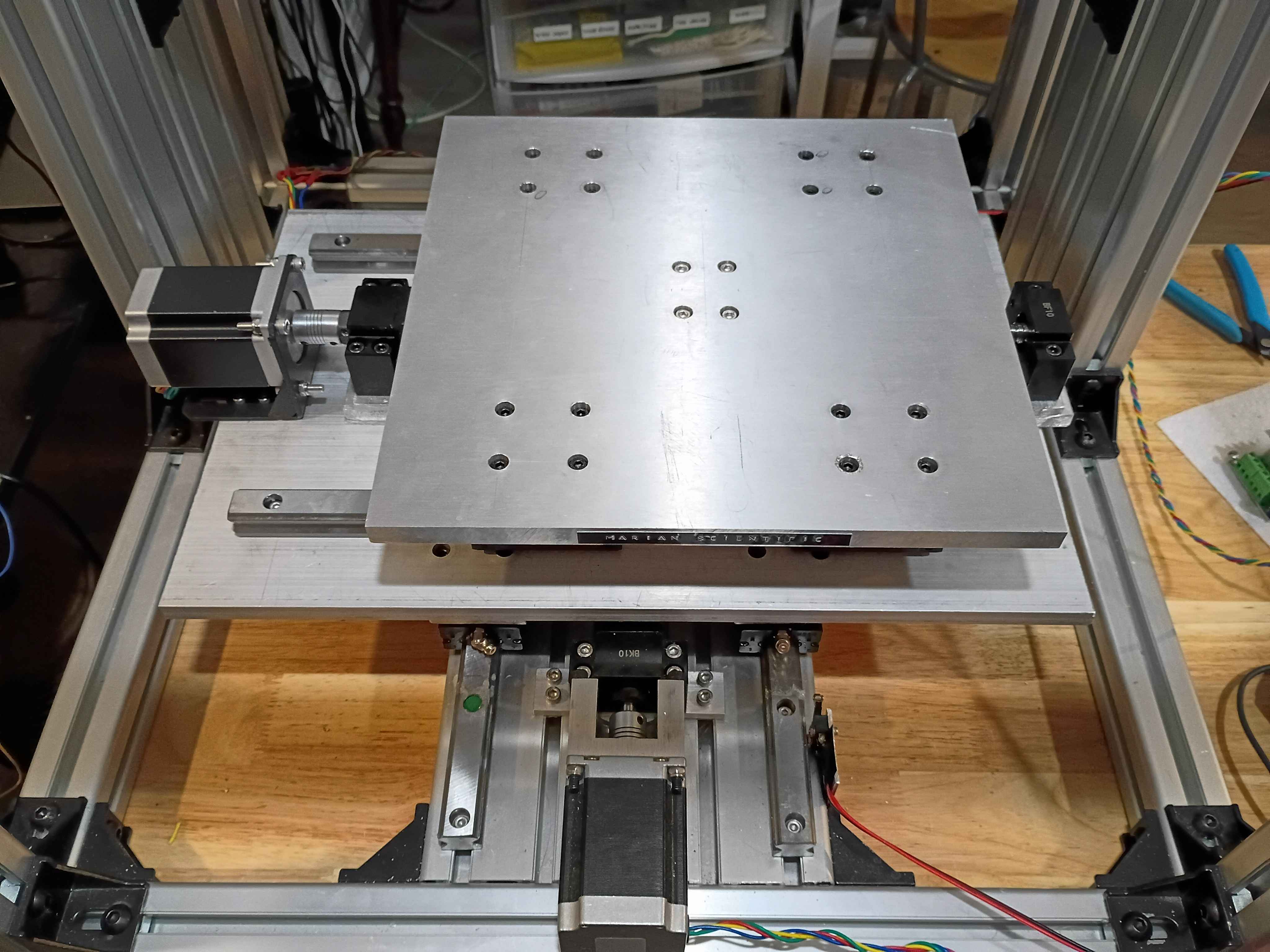
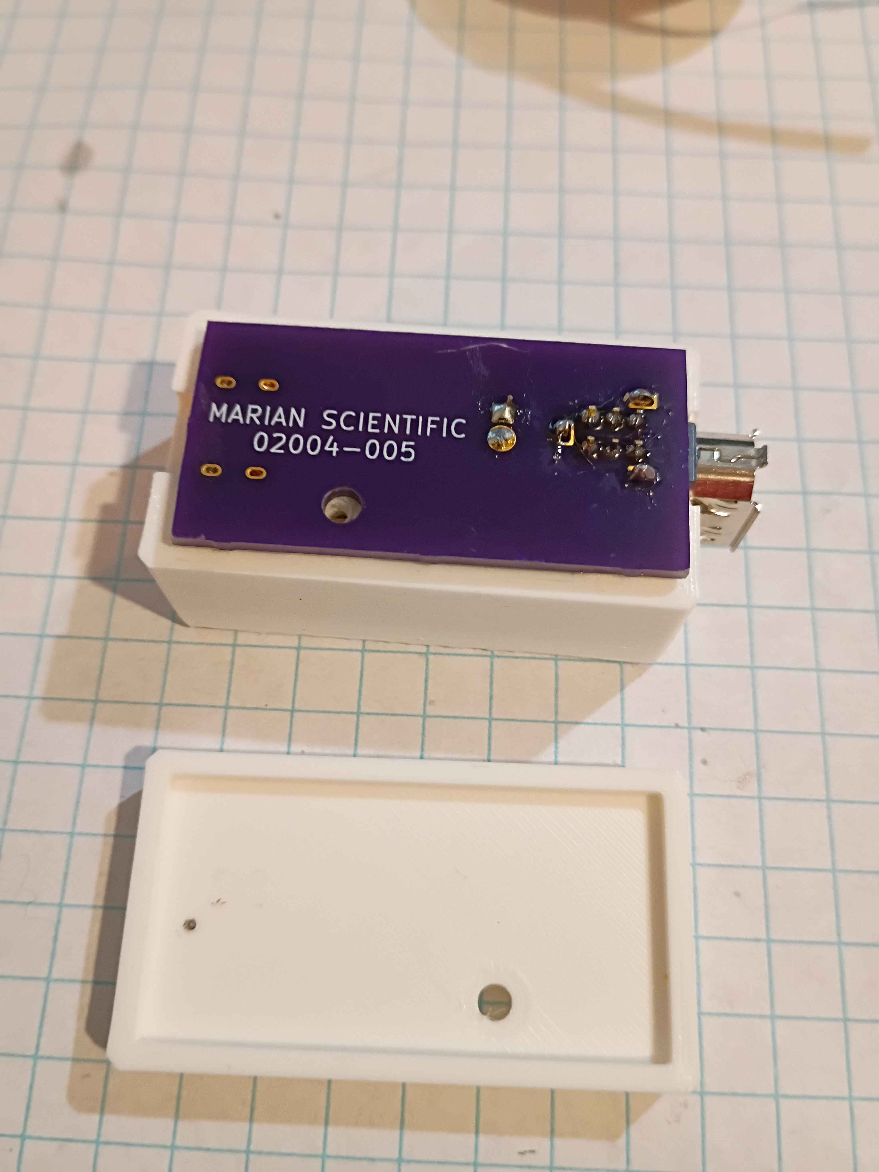
Redesigned 02004-007/008 assembly for the final time and printed 2 copies of each. Installed the 02004-005 PCBs. They actually work surprisingly well, though there is still a slight seam visible between them. 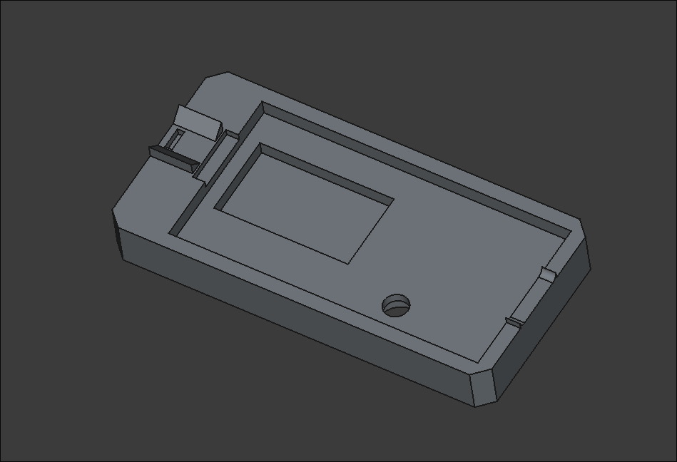
Added a dab of CA glue to the FireWire and USBC thru hole contacts for additional support. Revised and reprinted two iterations of the housing assembly out of ASA. I think I need one final reprint of the smaller piece with a slightly deeper recess. 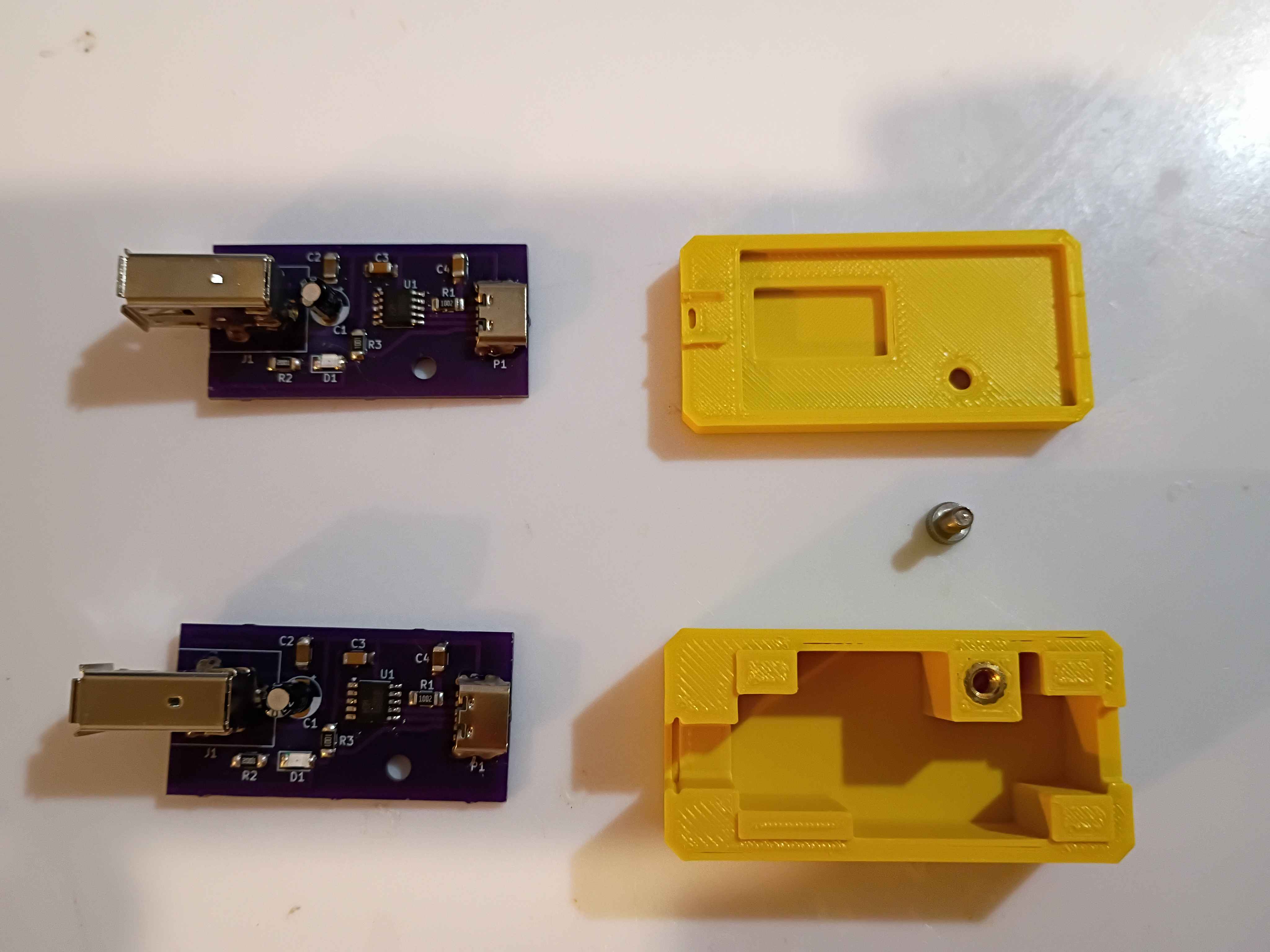
Designed RGB LED mount and breakout board for in-house fabrication. Board size is 10x10mm. 
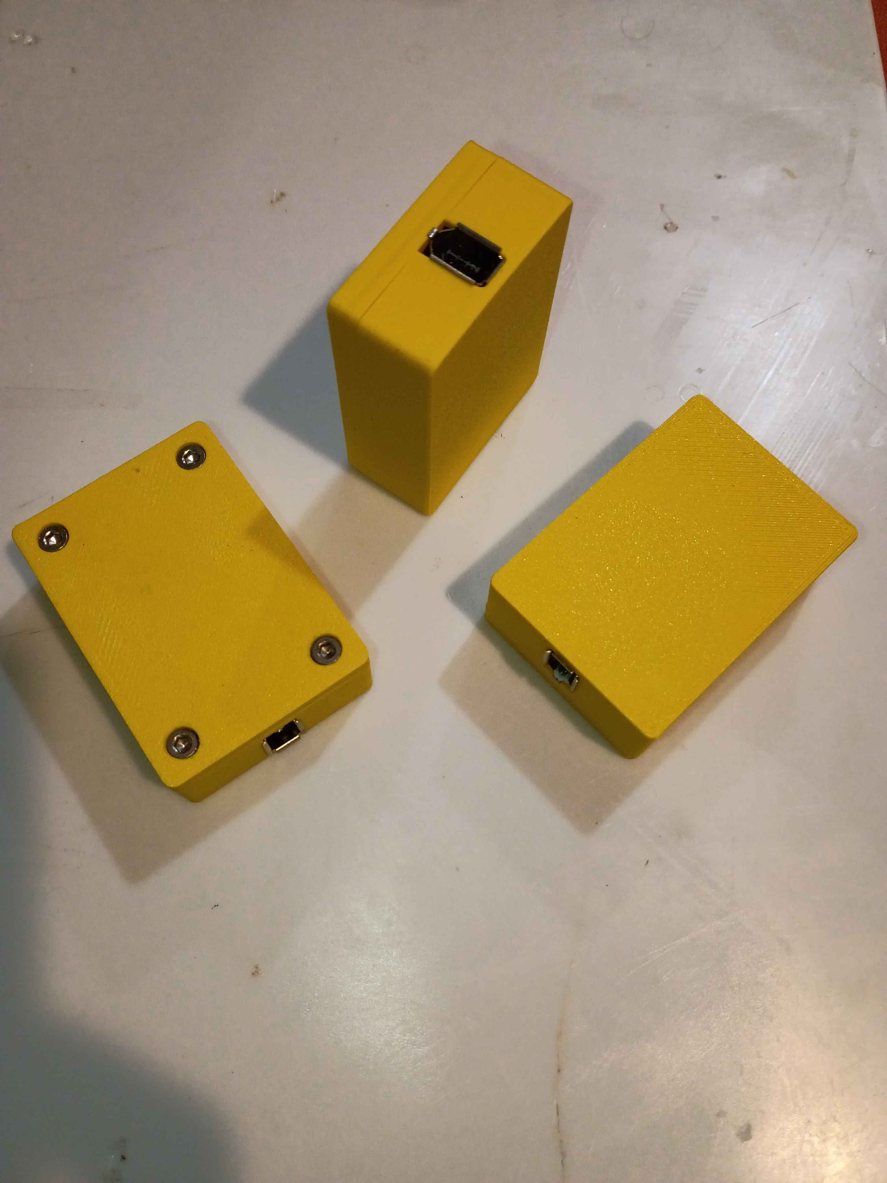
Successfully soldered and tested 2 more boards. Redesigned the housing based on lessons learned from the first box prototype yesterday. Parts are printing overnight, and the assembly will be tested tomorrow. 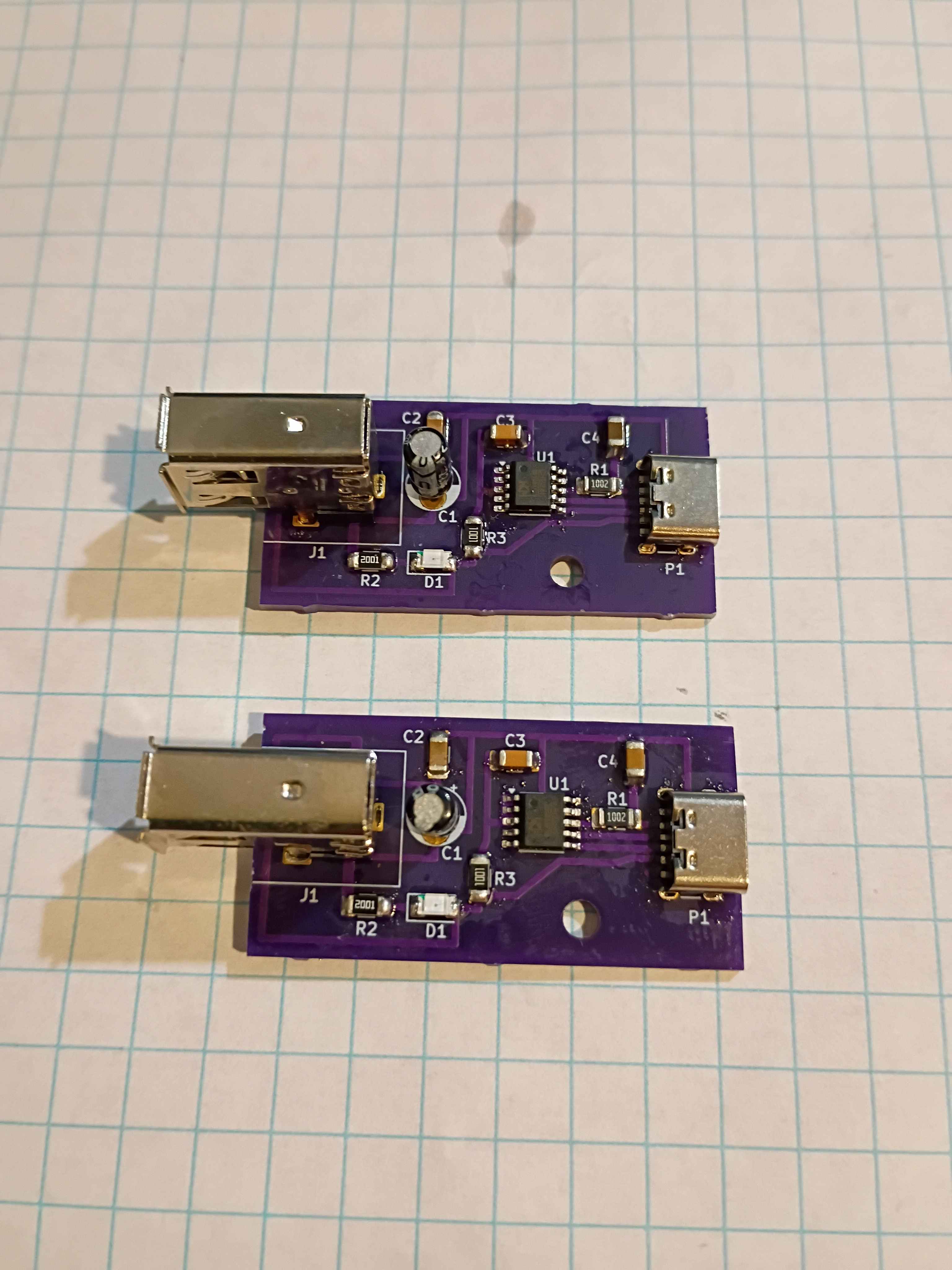
Received 02004-005 PCBs from OSHPark. High quality, as usual, but took 7 business days, with the fastest processing and 2-day shipping, plus 2 weekends. Still good in a pinch, I suppose. Designed and printed a 2-piece housing, though several details will need to change before it works perfectly. Used hot plate for the first time to solder most of the components, which went pretty well, and did the FireWire and thru-hole capacitor by hand. I think some components (including CH224K) were shorted because I put too much solder paste, so ultimately I had to scrap the first board, though I have 2 more to try. 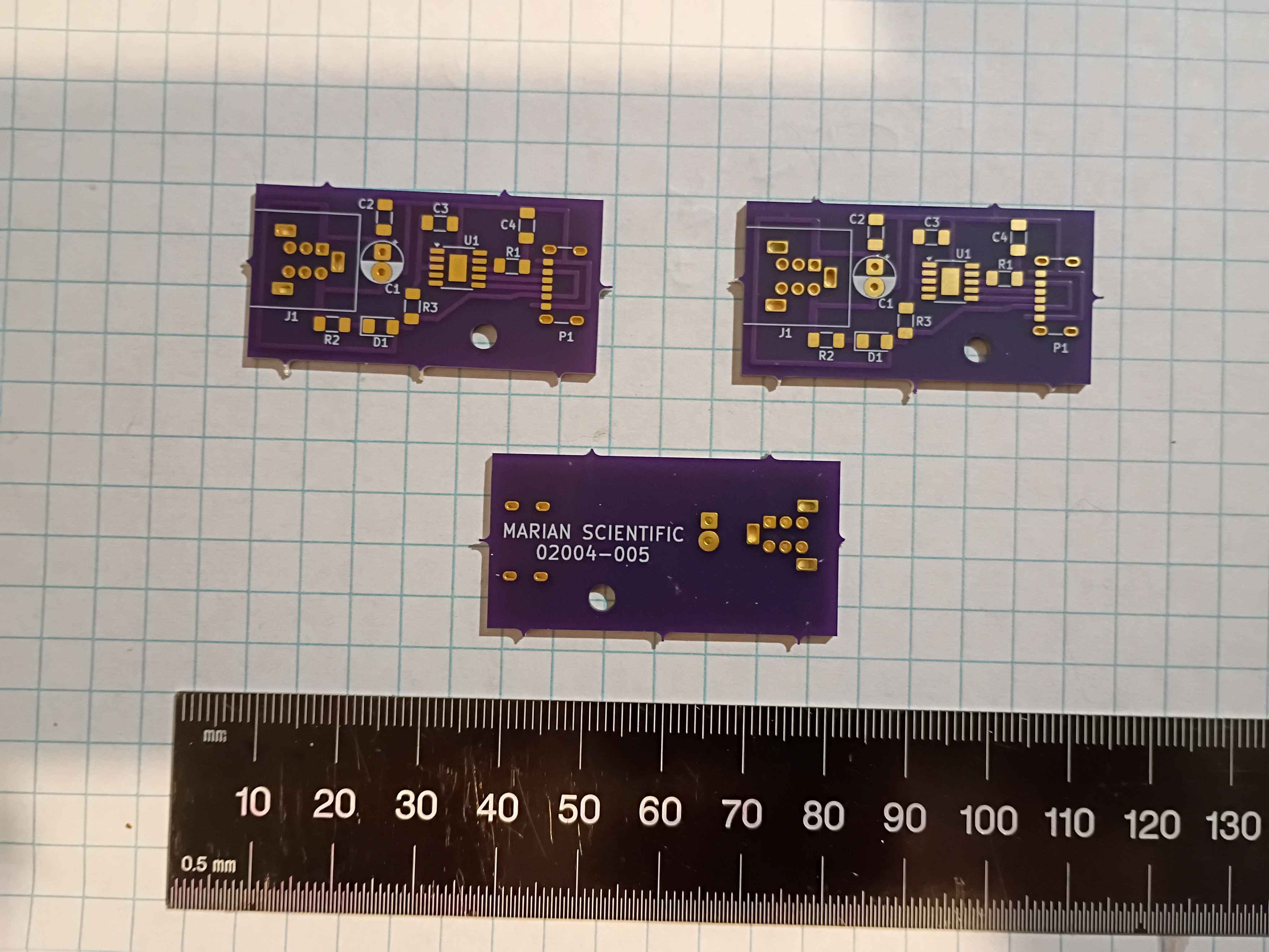
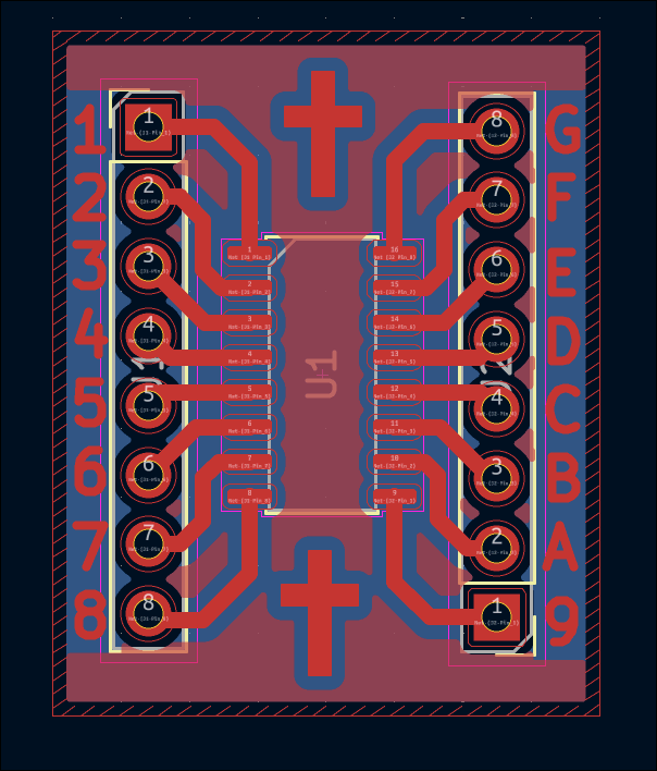
Designed breakout PCB for generic 16-SOP IC (in this case, for the CH32V003A4M6 MCU). As a test, embedded some crosses and text in the copper layer to attempt that. This is for testing of the IC to be used for the stepper motor controller. 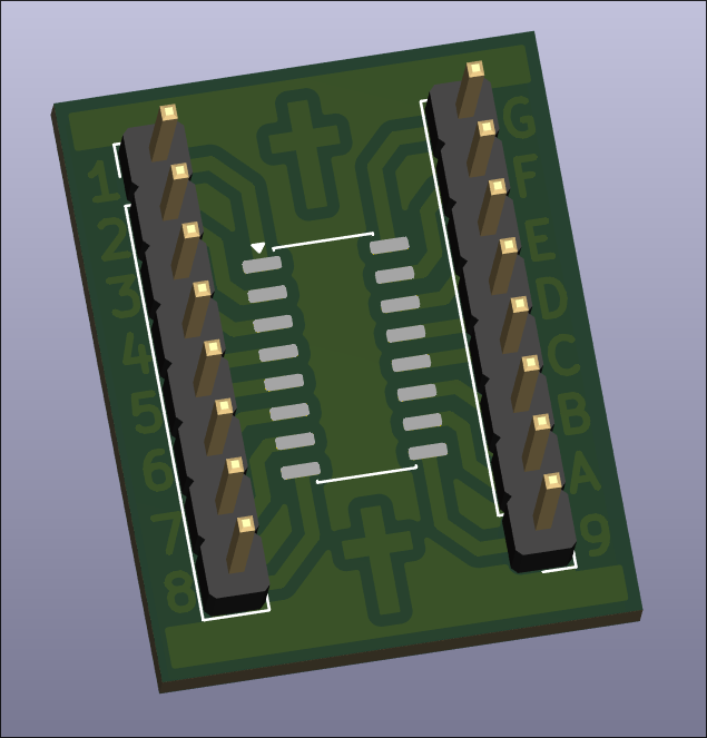
Created logic-level-shift PCB design with built-in LED indicators and ordered on OSHPark. 
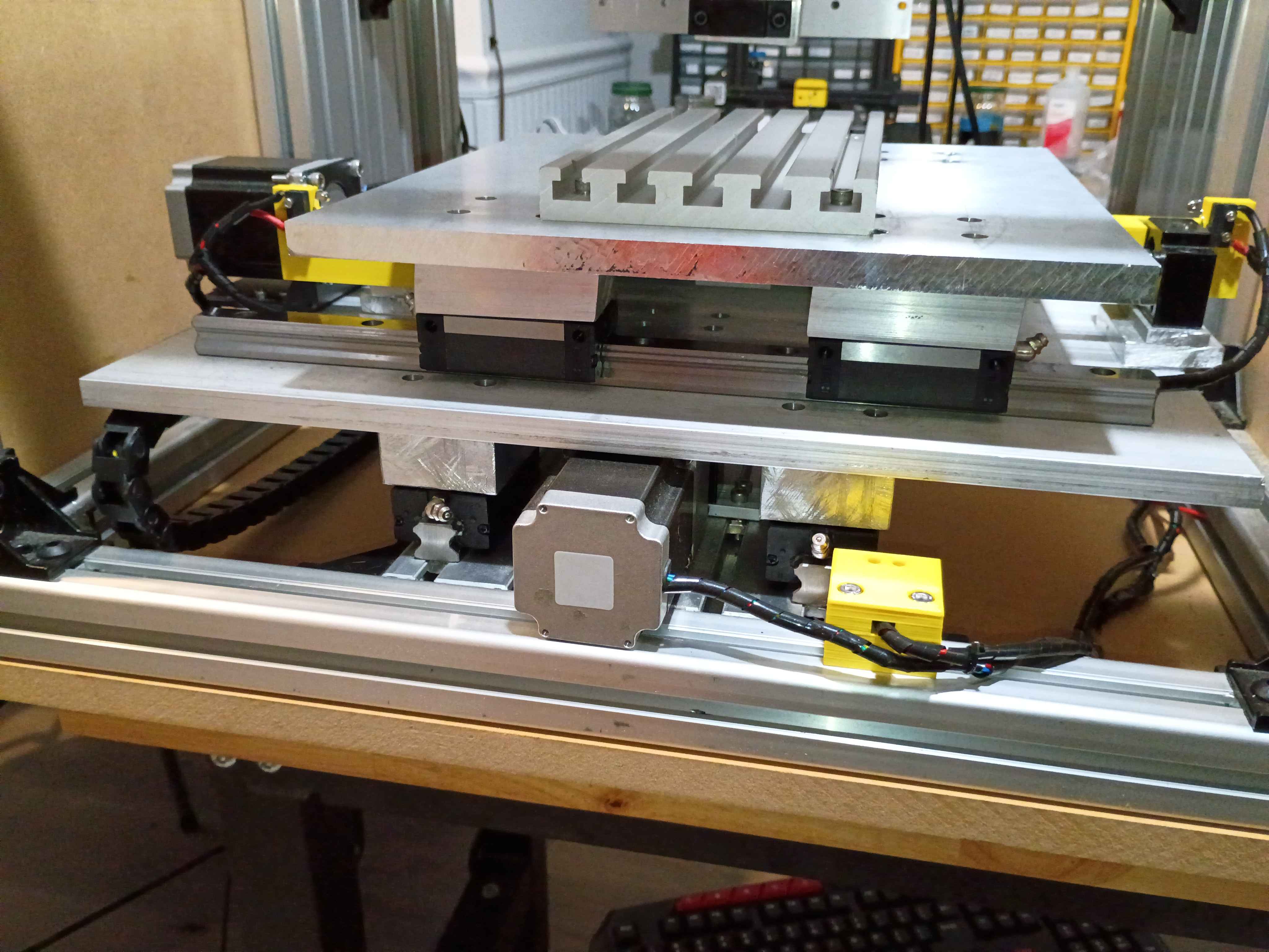
Cut, drilled and installed shims under the gantry plate. Also reversed the 2 upper mounting screws on the y-axis stepper. Altogether that gives roughly 110mm of motion. I will have to drill out some of the holes a bit wider and possibly straighten the rails because currently there is some binding in the Y-direction motion. 
Installed gantry plate successfully, but apparently there is insufficient clearance with the ballscrew support blocks for more than 1 inch of motion in the Y-direction. I will need an additional 2mm shim on all carriages and possible 3mm on the ballscrew follower nut. 
Created 03007-003 PCB design for a single H-bridge stepper driver using SMD components. Submitted board for fabrication at OSHPark, though this could technically be fabbed in house. 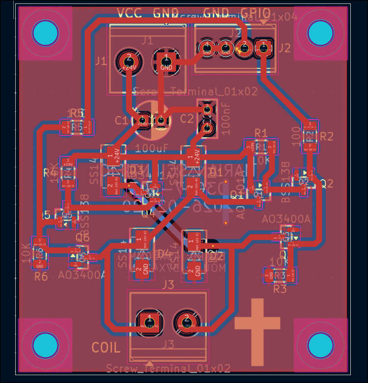
Cut, filed, drilled, and deburred 4x linear rail carriage mount spacers for the y-axis motion system. Ordered the corresponding length screws to mount the gantry plate.
Created a Marian Scientific KiCad project template that has a basic PCB with mounting holes, the minimum silkscreen info required per company standards, and a bunch of settings set up for both an in-house and professional board fabrication. Click here for the template. 
Reversed the diodes on the first soldered board and retested, which still showed a short. Realized I had some of the P and N channel MOSFETs installed in the wrong spots. Would have been good to label them on the silkscreen. I just soldered 4 other boards with the correct components and they seem to work, though I have not fully tested them all with coil loads. I did not have enough P-channel MOSFETs so I reused some old (potentially shot) ones. I have marked them to help identify them if an issue arises in the future. I updated the schematic and PCB design to reflect these revisions, rolling the part rev to 03007-001-A. It counts as a revision, not a new part number because the board has the same form, fit, & function as the sibling -001. 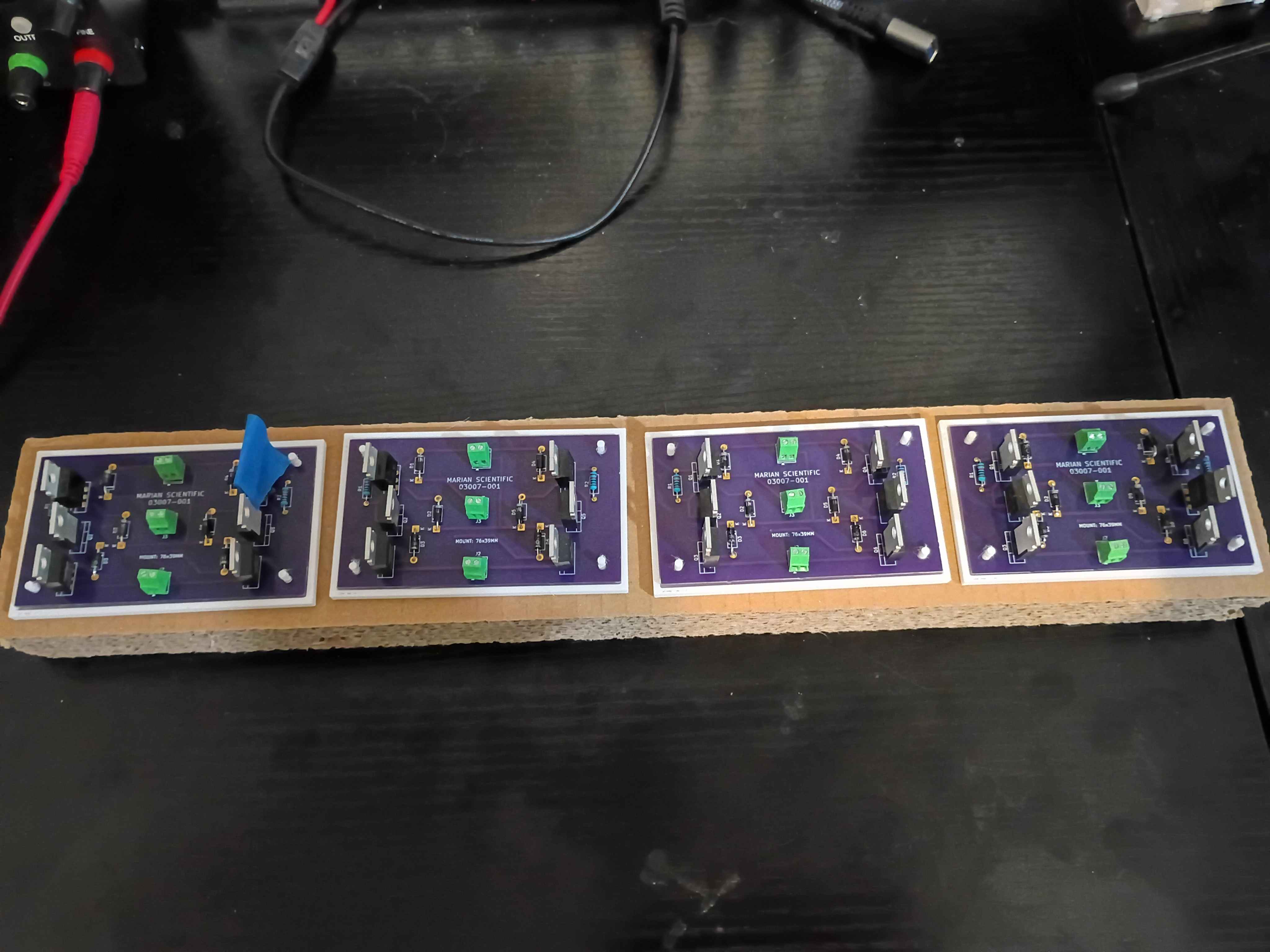
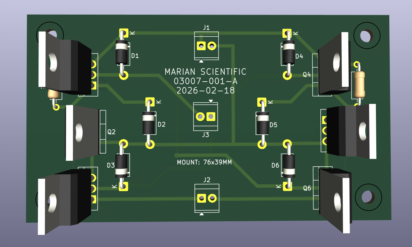
Printed a set of 4 PCB holders and began to electrically test the first board. After some debugging, realized that the schematic and front silkscreen have the diodes going the wrong way, which I installed the diodes to match. These 6 components need to be desoldered and reversed and the board silkscreen design technically revised. 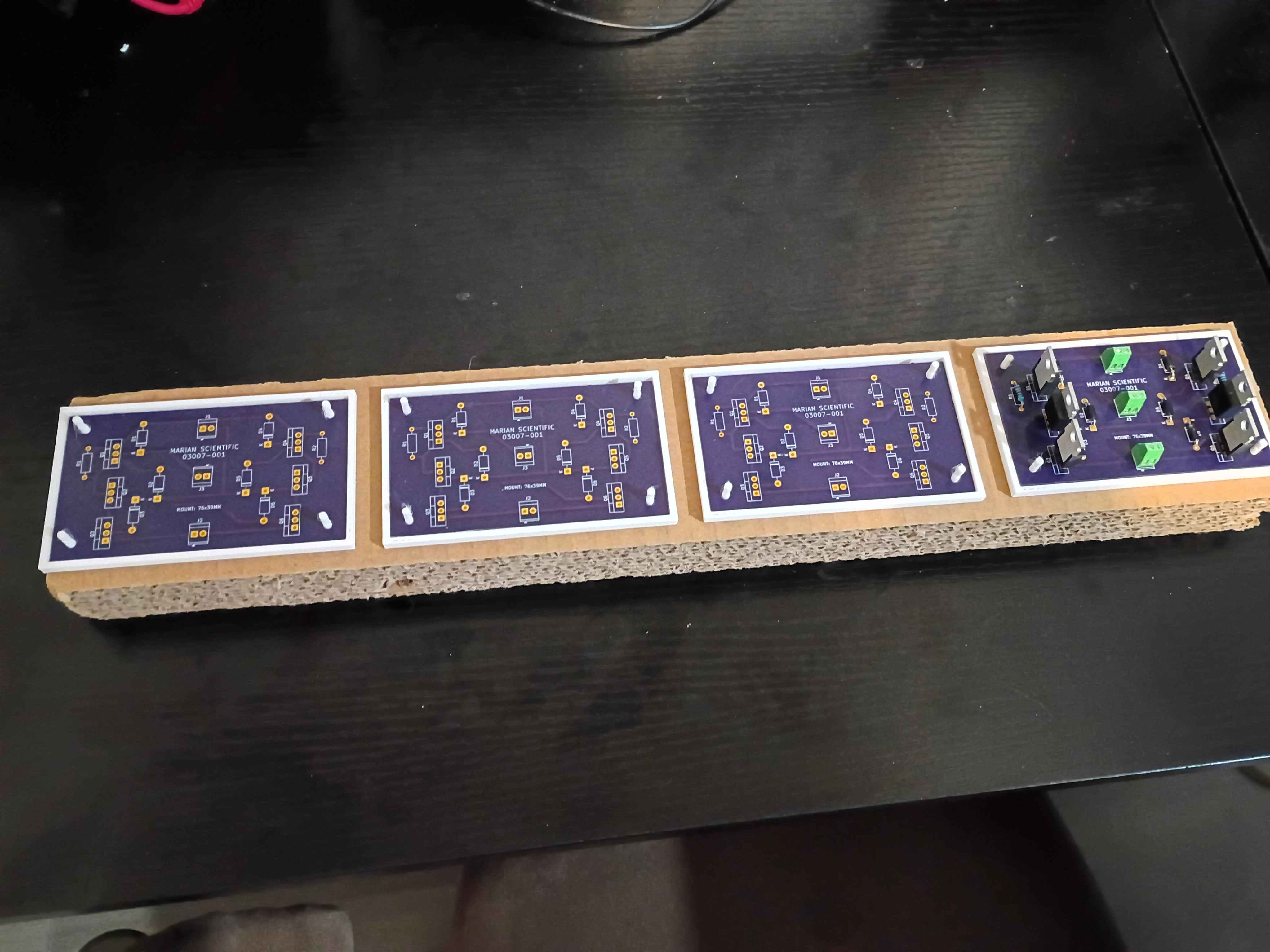
Bolted down Y-axis ballscrew supports, installed lubrication nipples, vacuumed the entire assembly, and lubricated the rails and screw. 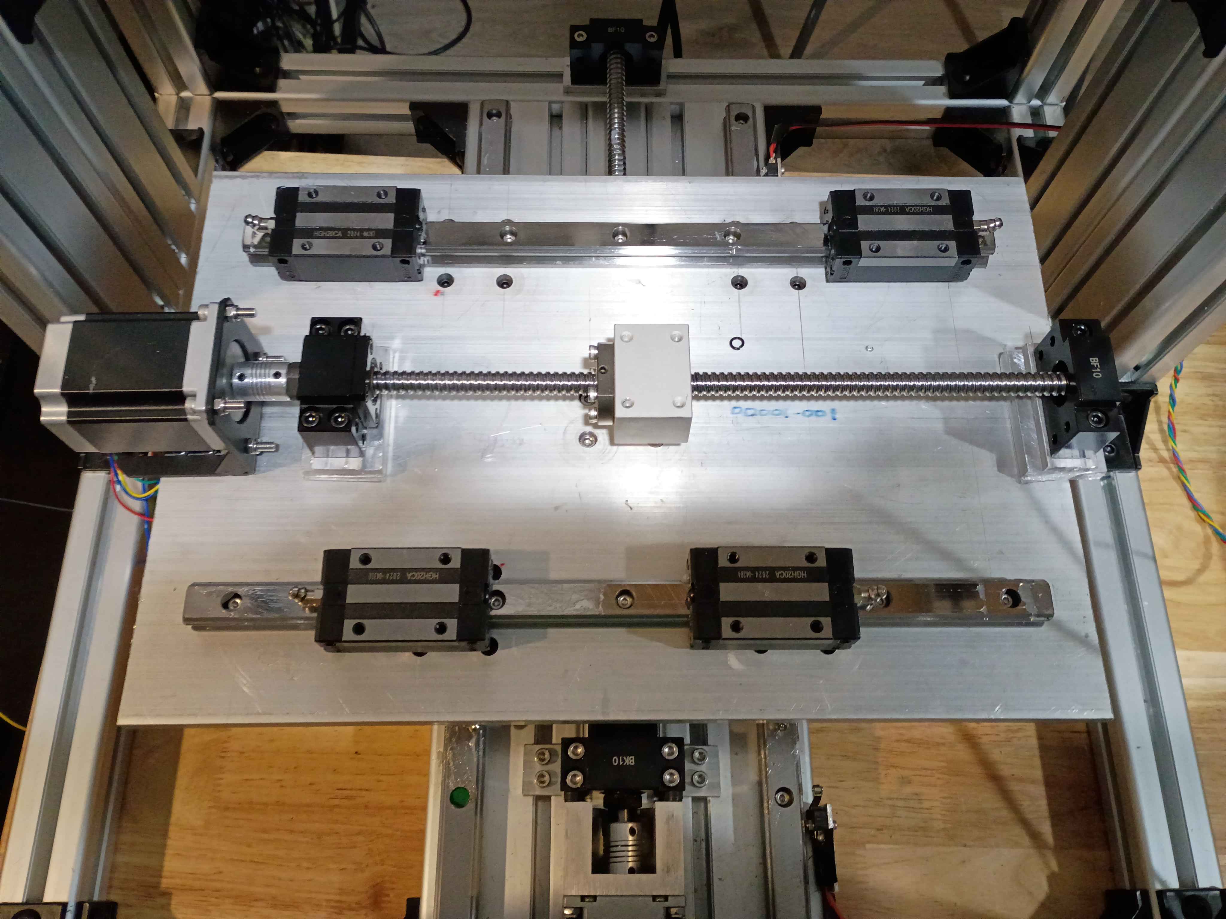
Removed silicone mat from the tool and installed edge magnets. Overall the proof-of-concept was a success, but in the future I would like to use thicker magnets set in a thicker wall and with a vent hole in the upper mold tool somewhere to prevent leakage. 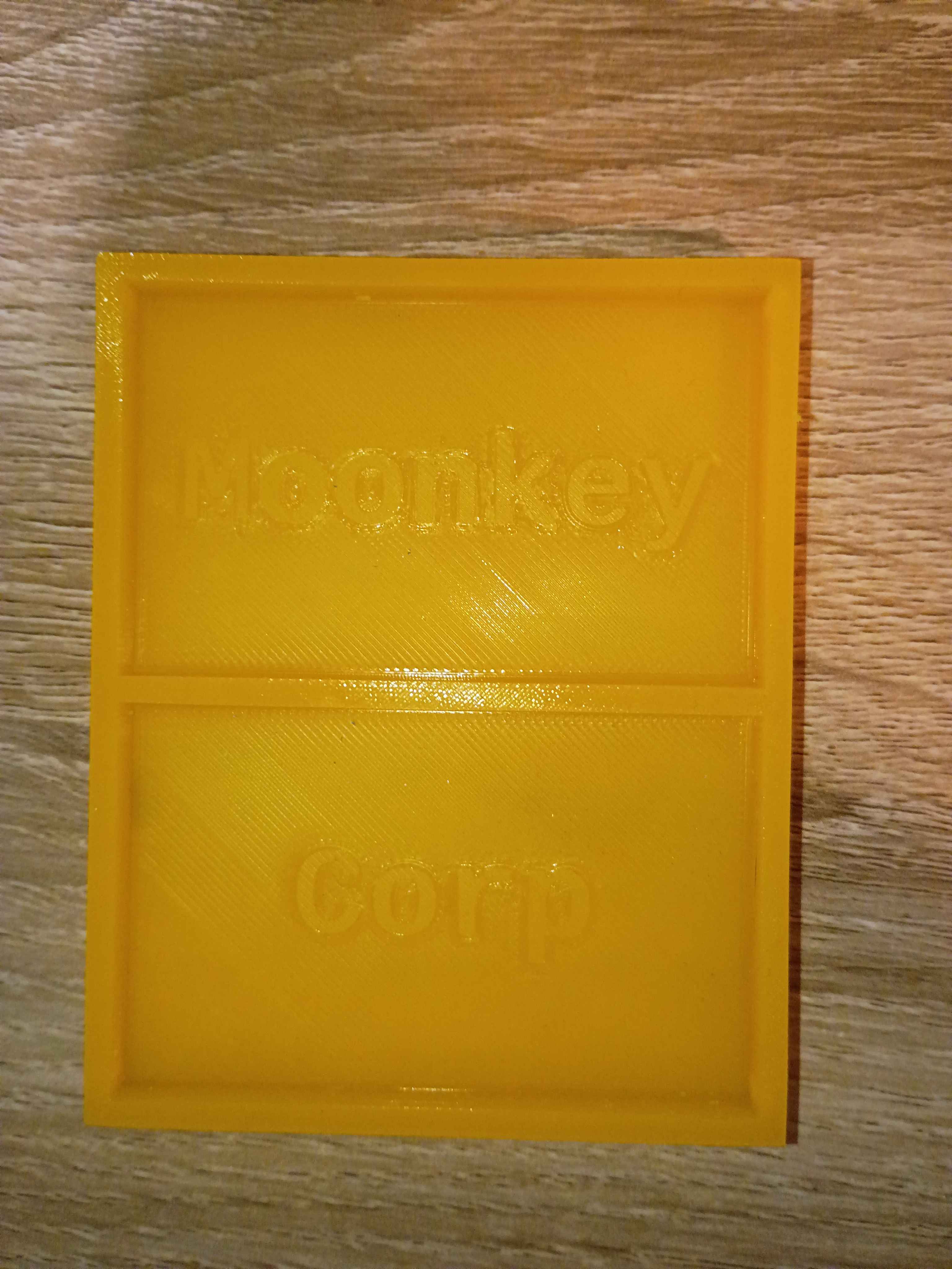
Installed ballscrew nut follower onto Y ballscrew. Determined height of linear rail carriage spacers (25mm ~ 1in) and ordered some aluminum stock for that purpose. Also printed templates for the clearance hole patterns. To simplify this process going forward, I spent some time configuring my network printers.
Modeled and submitted for print a holder for the 03007-001 stepper driver PCB. 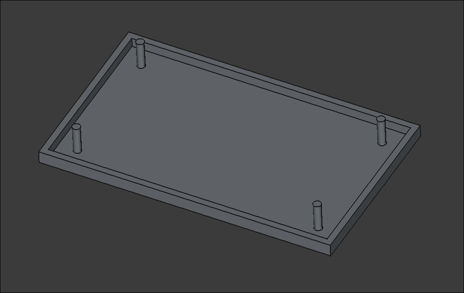
Cut, filed, and drilled clearance holes in some spacers for the ball screw support blocks for the XY gantry motion. Took a while to saw because my hacksaw blade is getting quite dull. Used Inkscape, my printer, and a gluestick for the first time in this application to actually mark out the drill locations, which worked swimmingly. I do need longer M5 bolts to mount these, however. 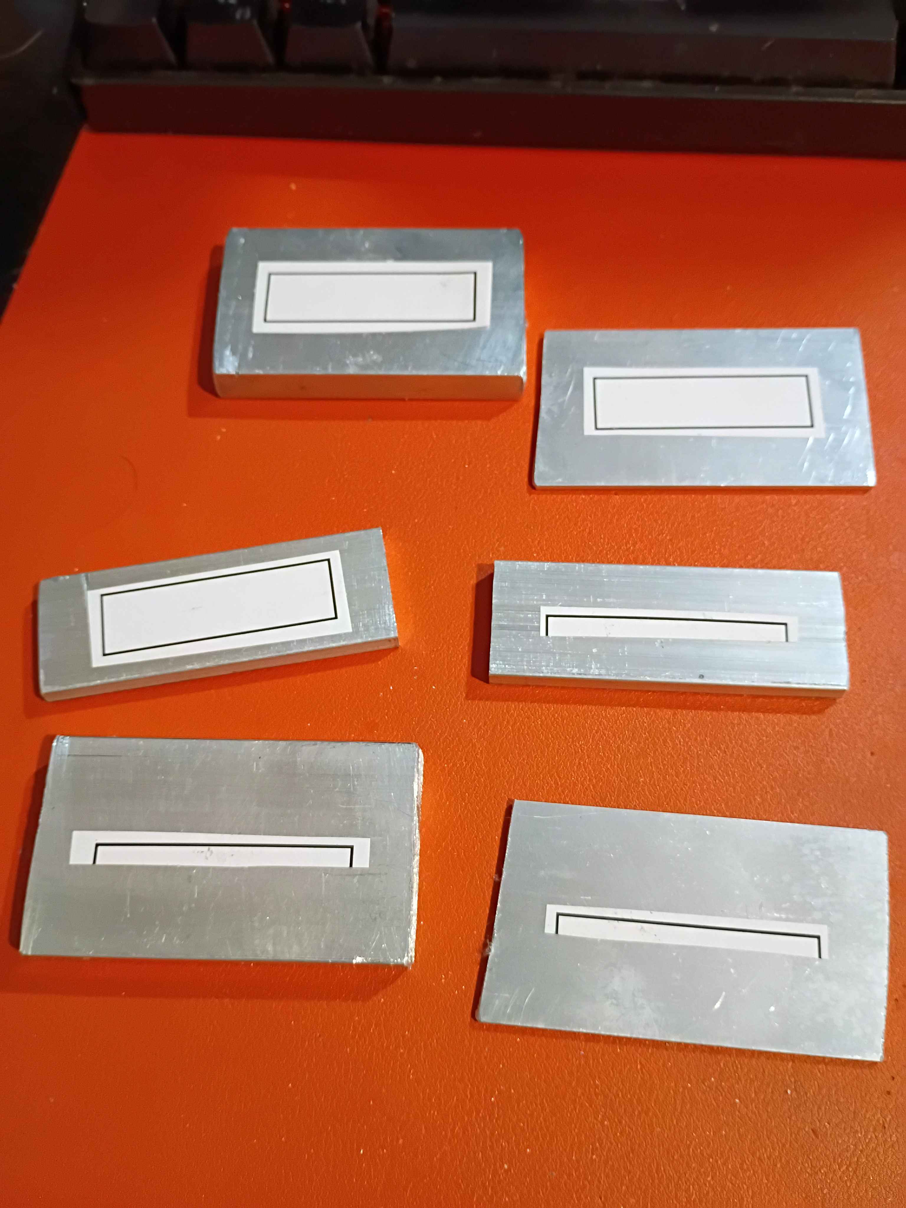
Attempted a silicone cast of the mini mat. Also had to reprint the primary clamshell mold piece due to having the text incorrectly mirrored on the first print. Due to the lack of air, I will give it 24 hours to cure and report back tomorrow. 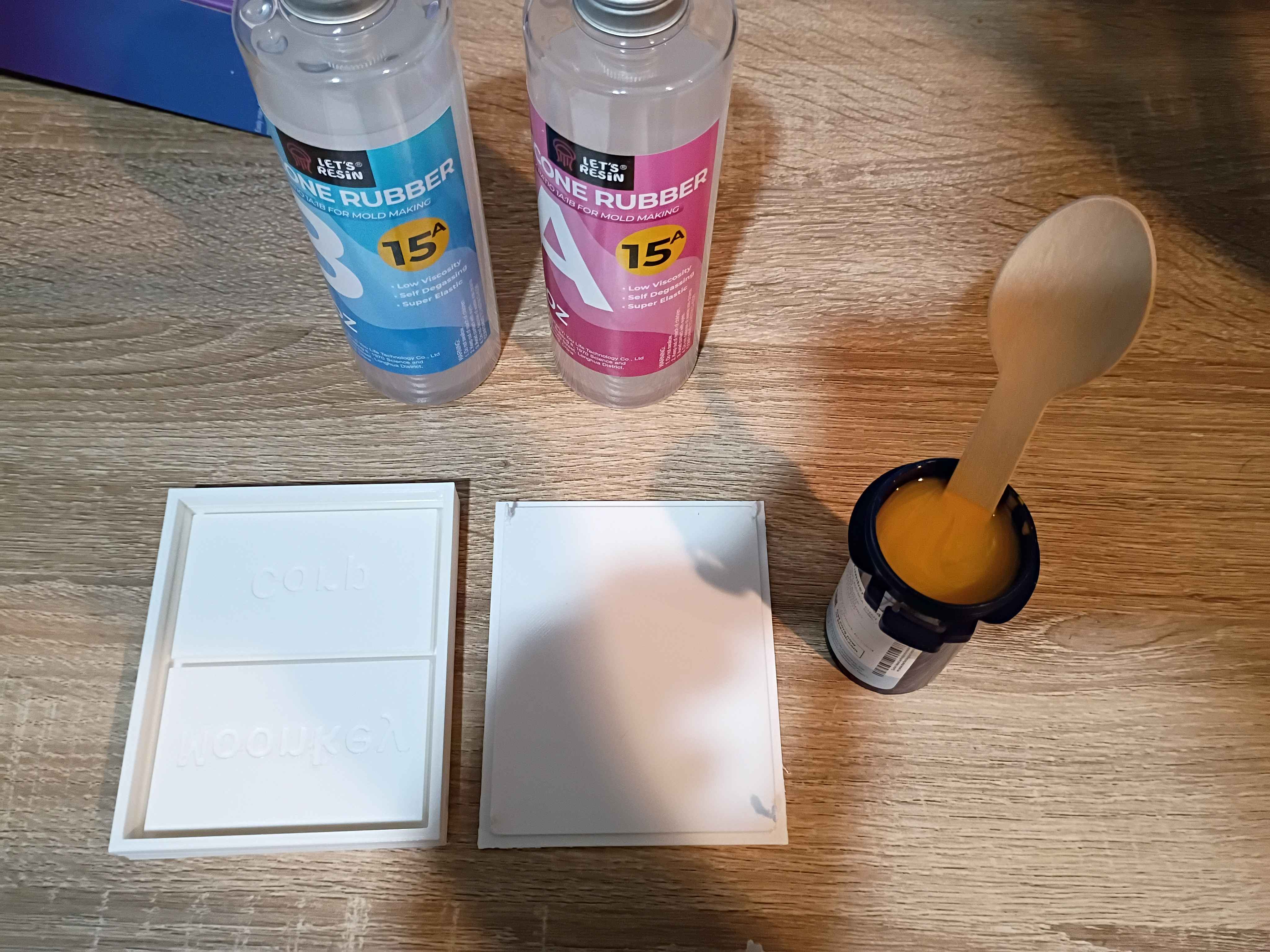
Added grant budget processing to Mary-Bot. All authorized organization members can submit a !grantrequest and check the !grantbalance, but only requests submitted/approved by Matt will be tabulated.
Designed and printed 2-part test mold for a silicone mat with slots for embedded magnets. This is ultimately for a potential client. 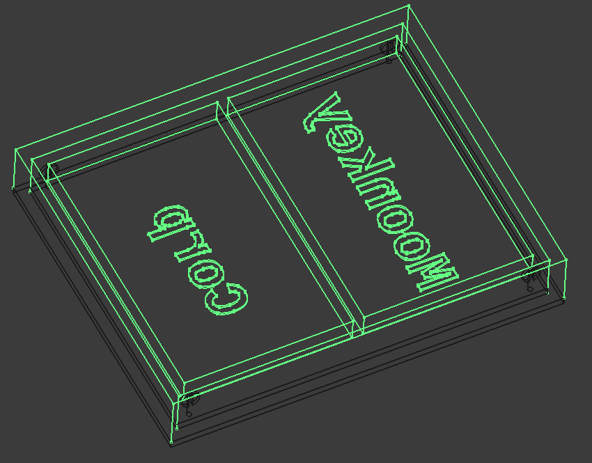
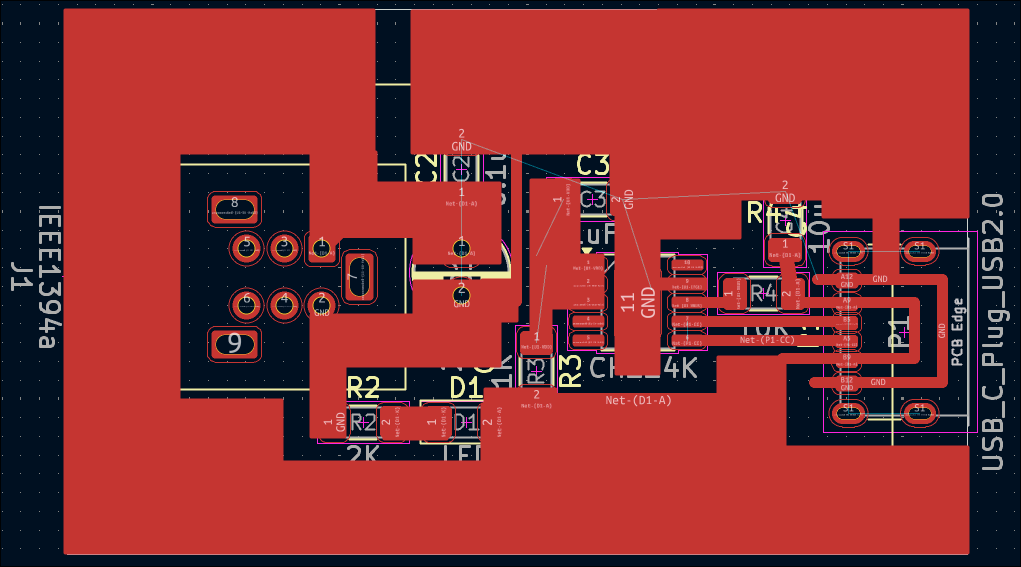
Shrunk the previously-validated 02004-004 PCB design by removing the hole pattern and adjusting the components slightly, creating the 02004-005 PCB shown below, which is 43x21.5mm. As a test of OSHPark's fulfillment speed, I ordered 3 of them (normally $7 for 3 with free shipping) with their Super Swift Service (half the processing time) and added $10 2-day Fedex shipping. It should also be noted that OSHPark lets you reupload and overwrite your designs (provided the new one is the same size) up until they are panelized. 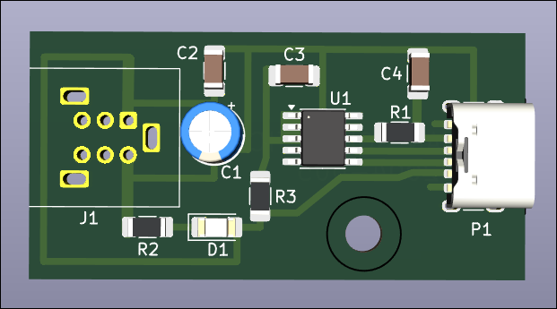
Etched the newer smaller 02004-004 trigger board. Designed and printed the 02004-004T1 drill guide to locate the mounting holes, and it worked absolutely perfectly. Popped the holes in and soldered the components. Put a few calculated drops of super glue to secure the connectors and successfully tested the circuit. Blue LED this time so I can save some green ones. Overall the fabrication went extremely well. 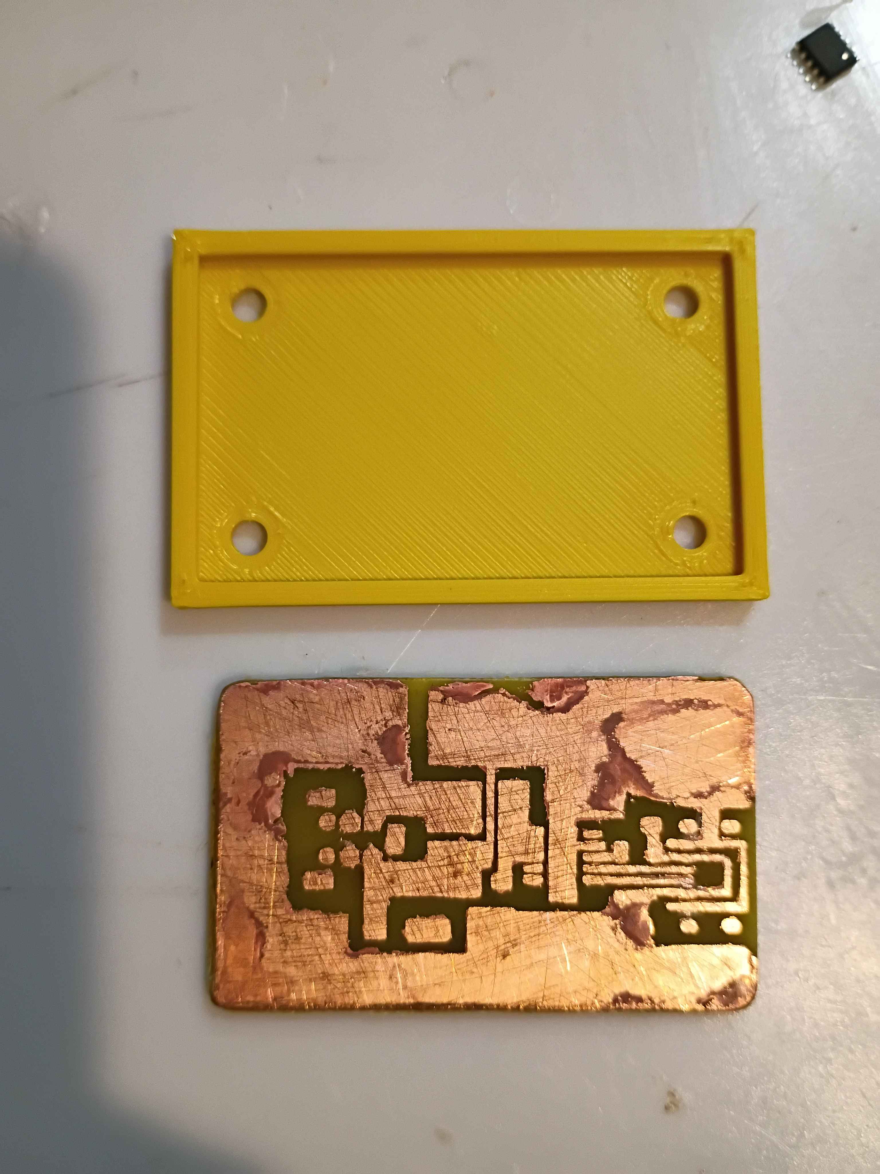
Repaired 1 of 2 additional evaluation units for the client and prepared them for shipment tomorrow. The other unit suffered too great of damage for repair, despite my best efforts. Developed a smaller and improved PCB design (02004-004) that removes the configuration resistor and jumper as well as increases the edge distance around the holes. This design is 8x7mm shorter and has several features for improved manufacturability. 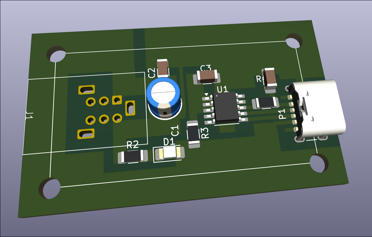
Notionally completed 2 more evaluation units, but determined after some testing that the USB-C connections are not adequate and need to be redone. Input provided to designer for future units but the current fabrication effort will require a clever approach. 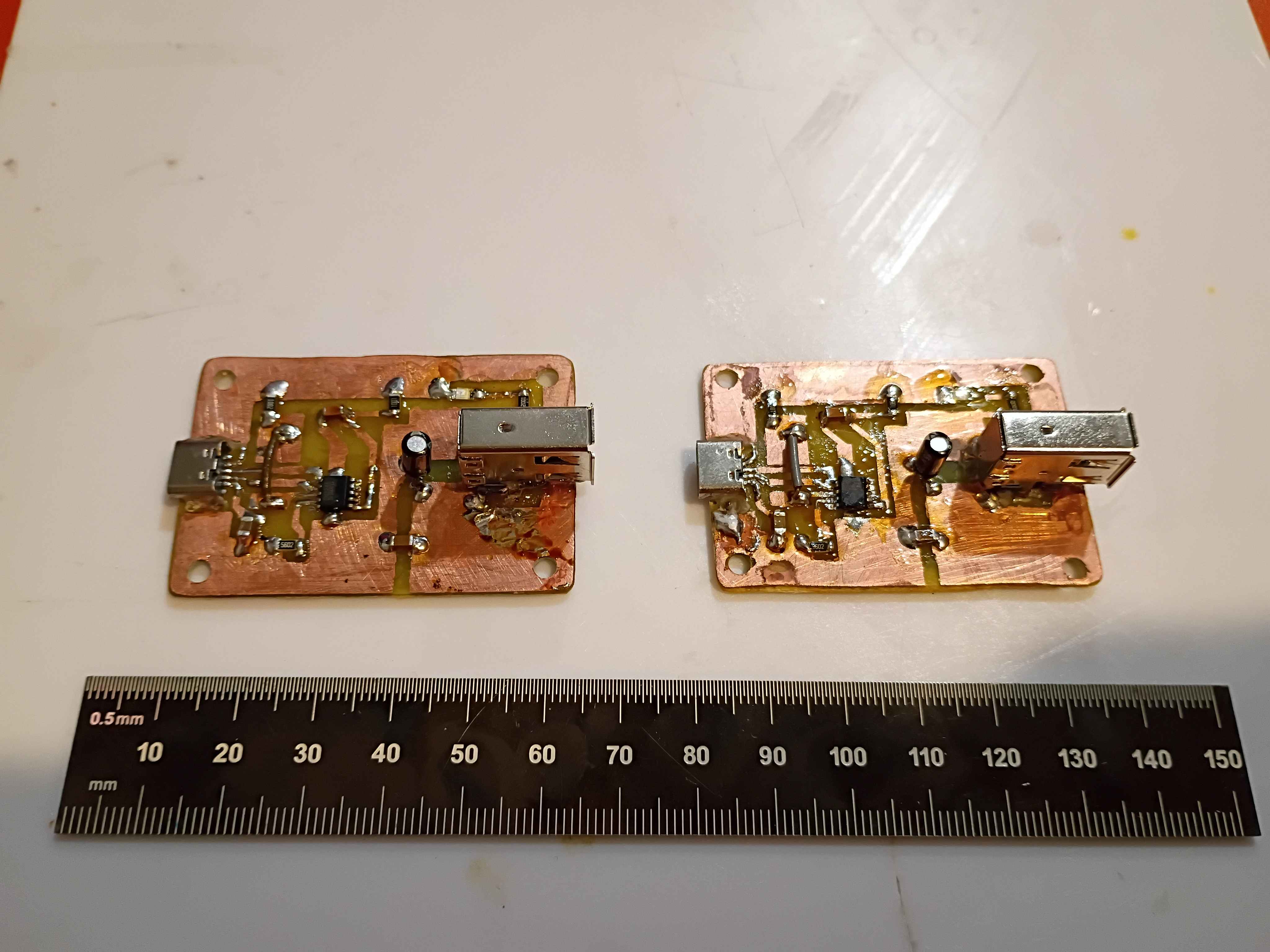
Began fabrication of 2 additional evaluation units for the client. Boards etched and drilled, and box assembly components printed, though one part requires reprinting due to some damage incurred during a prior attempted repair with a heat gun. 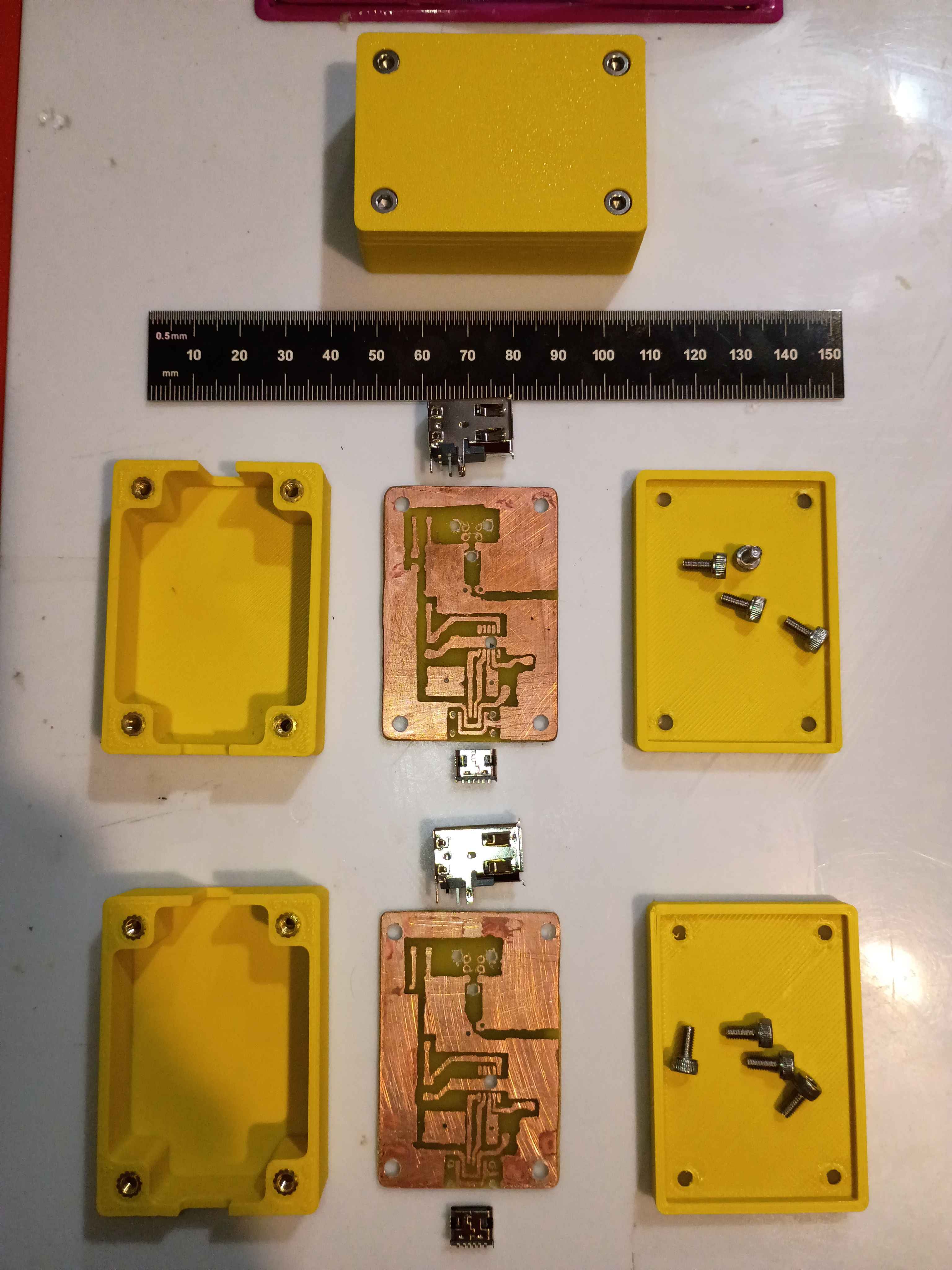
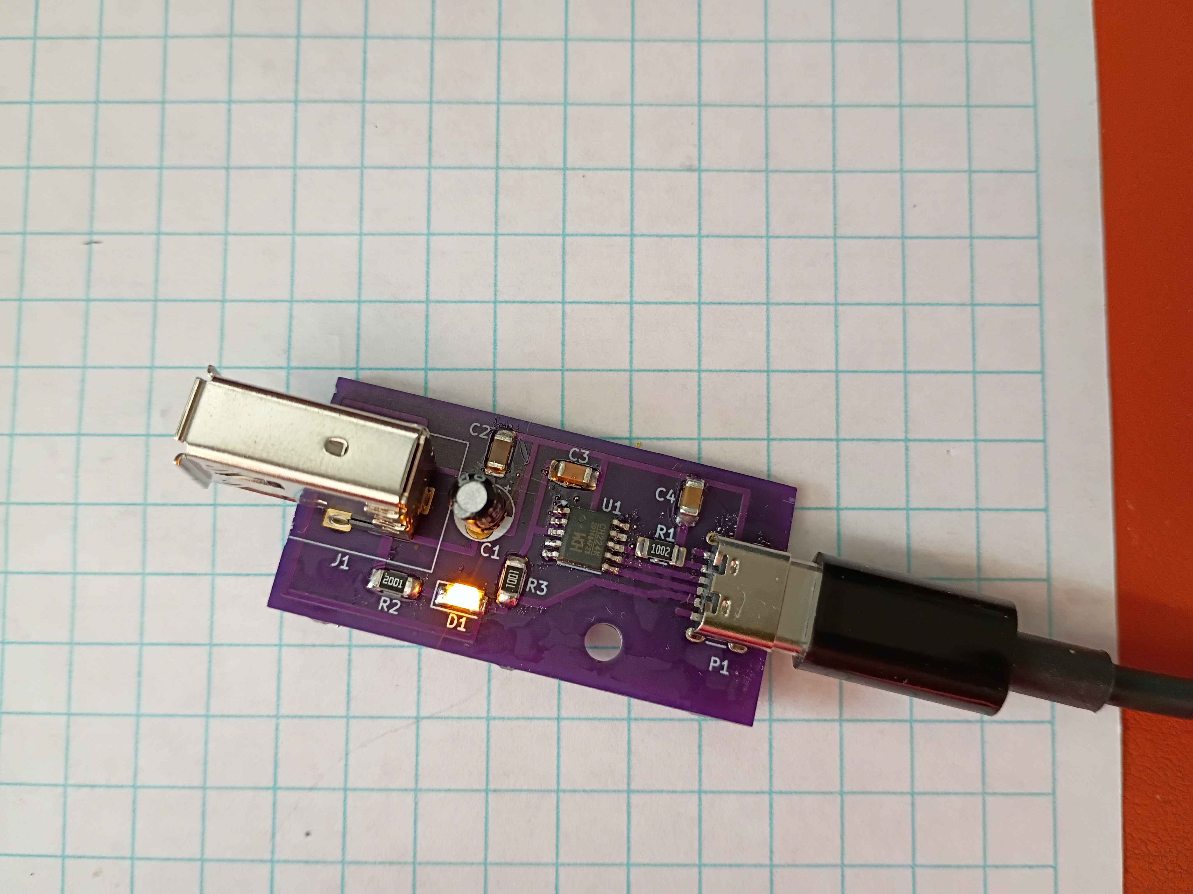
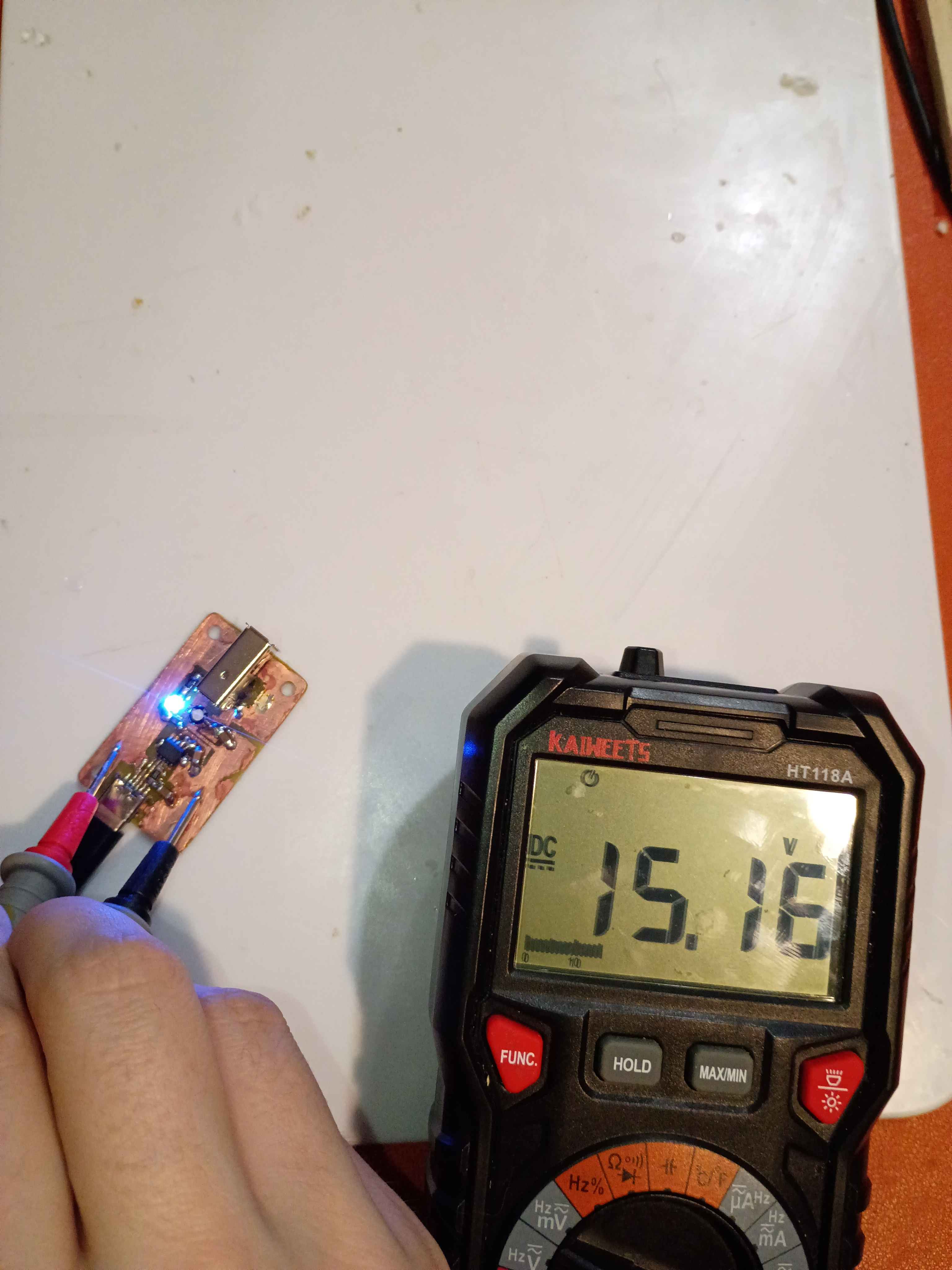
The circuit does seem to work with a 65W USB-C-PD charger, outputting the correct 15V. However, after repeated use, the USB-C port came a bit loose on the circuit and eventually detached. I resoldered it and applied even more super glue to secure it in place. I began reprinting the second case, this time letting the plate cool completely before popping off the print, in an attempt to remove the white haze from the bottom surface. 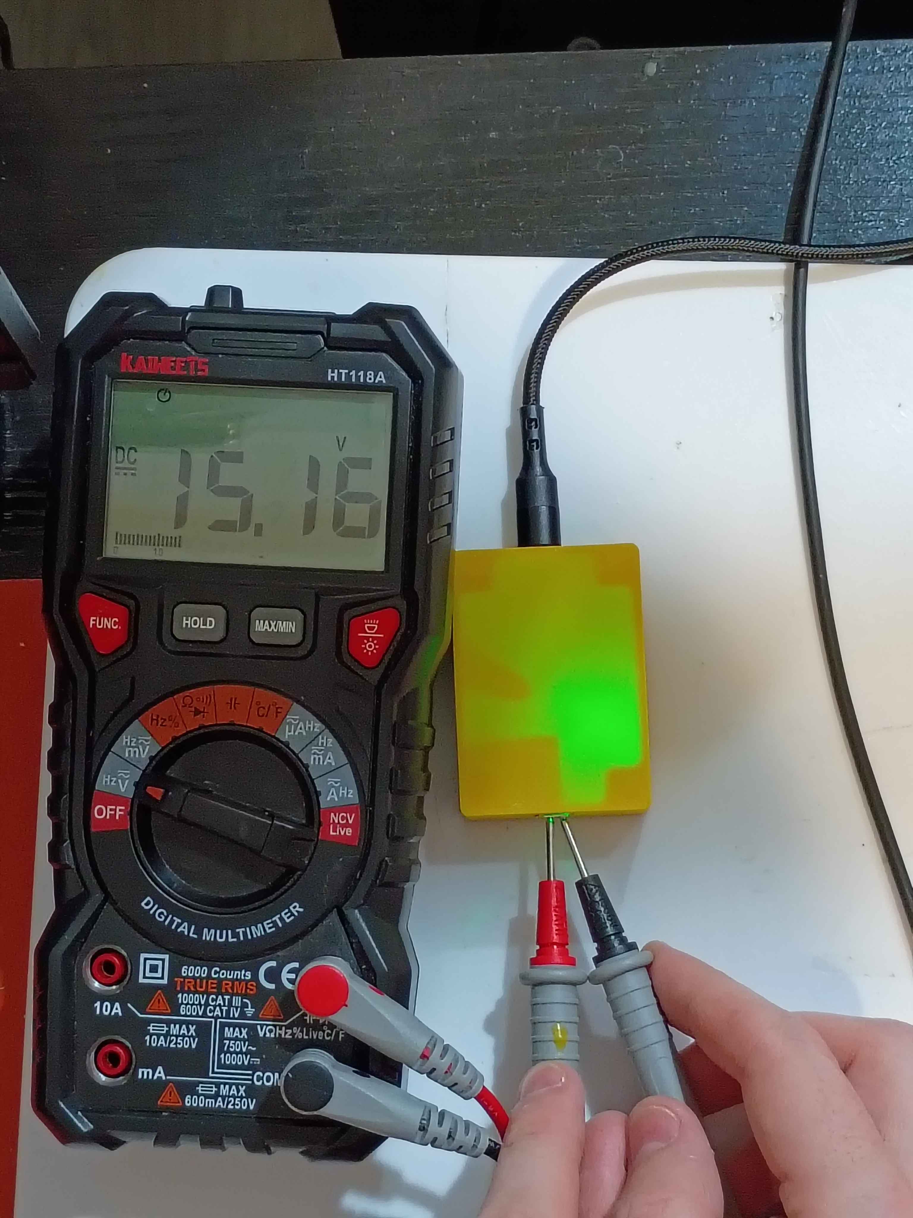
Printed revised box assembly out of ASA and assembled everything together. Had to tune the new printer for this filament for the first time. 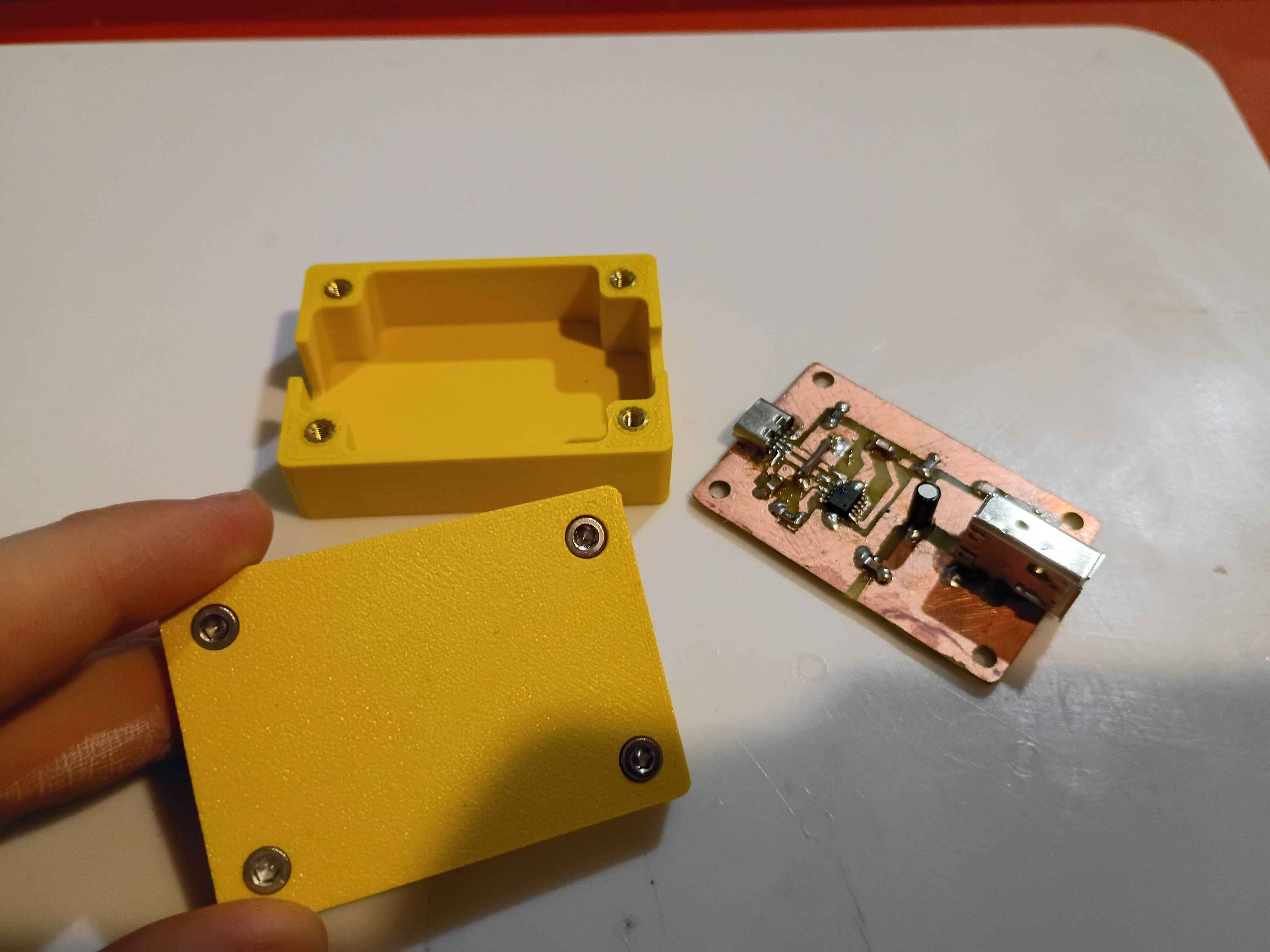
Completed second iteration of the prototype circuit board. It took 2.5 hours from printing the mask to testing the device. For future reference, I did immediately quench the board after toner transfer, so that didn't seem to make a difference. Still only get 12V max output, hopefully tomorrow I will receive a PD charger and cable capable of 15V. 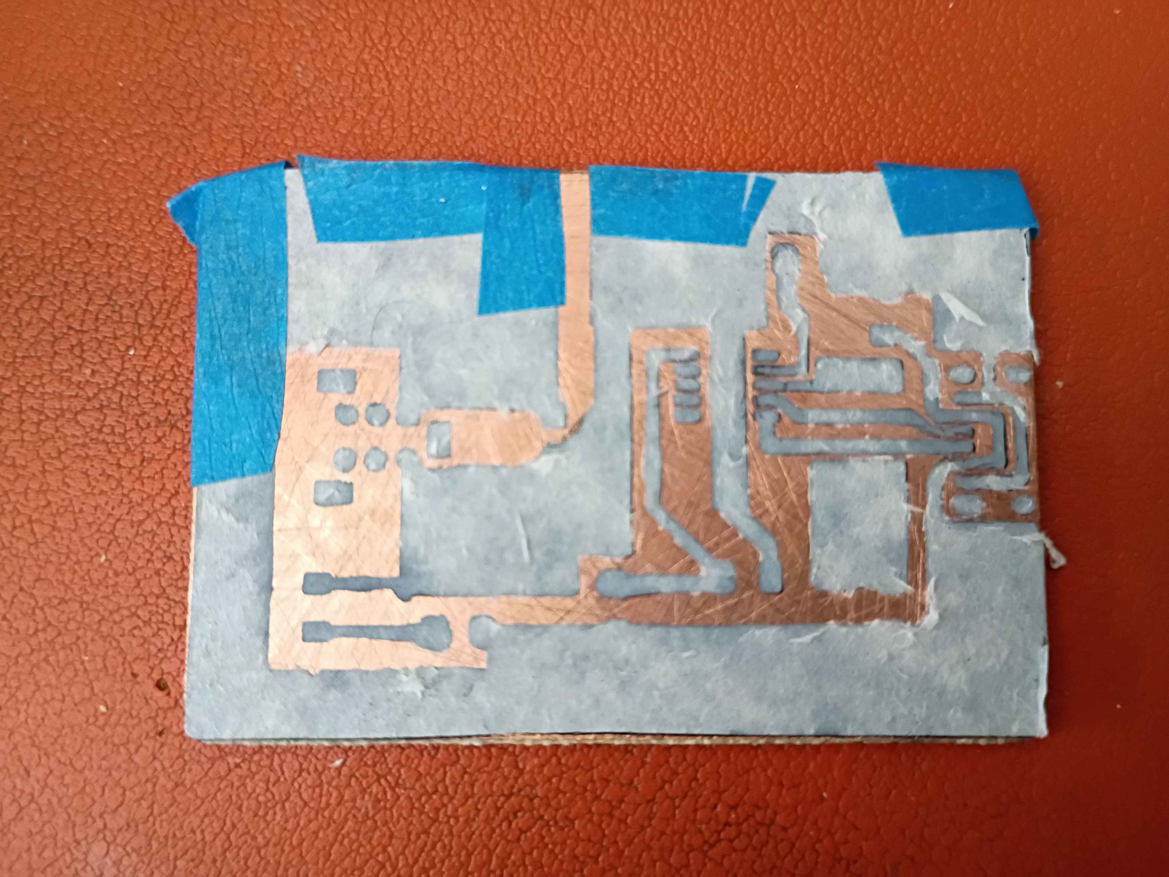
Received FireWire sockets and trigger IC and tried several iterations to get everything working. Eventually the circuit essentially works, though for whatever reason I was only able to negotiate 5, 9, and 12V. 15 and 20V did not work. I am sourcing different cables and chargers to see if that might have been the problem. Consulted on PCB design revisions for manufacturing considerations. 
Painstakingly filed the circuit board to size to fit into the box assembly. I really need to stop being so 'conservative' on the board snapping. Or just put a lot of extra clearance in these boxes. 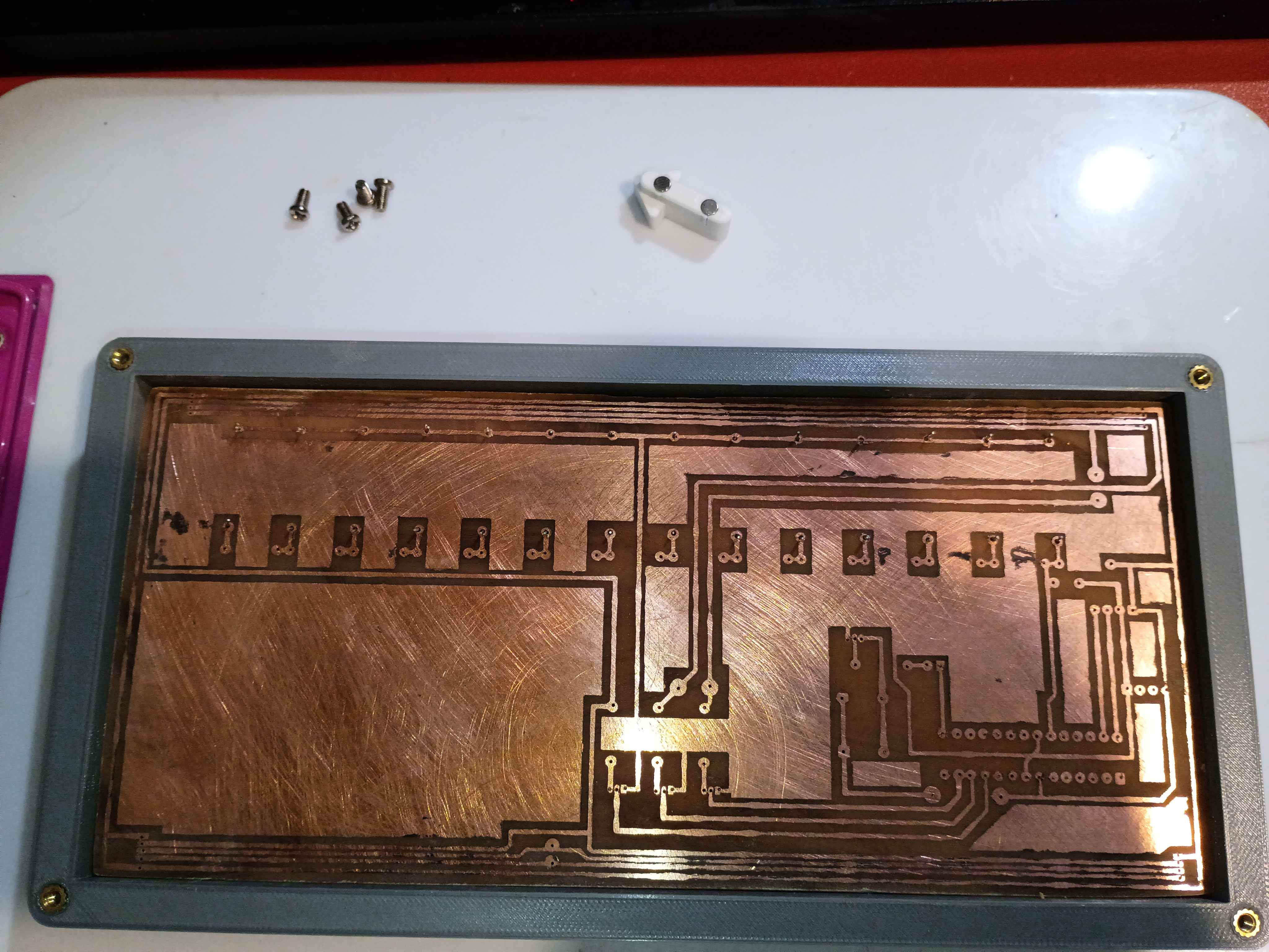
Reprinted slotted component with deeper slots. Bent and installed reed switches, put a dab of glue on each lead to keep them in place, and then installed the entire slot assembly onto the PCB. After testing with the magnetic input device, the slots are the perfect depth to prevent all false positive readings. 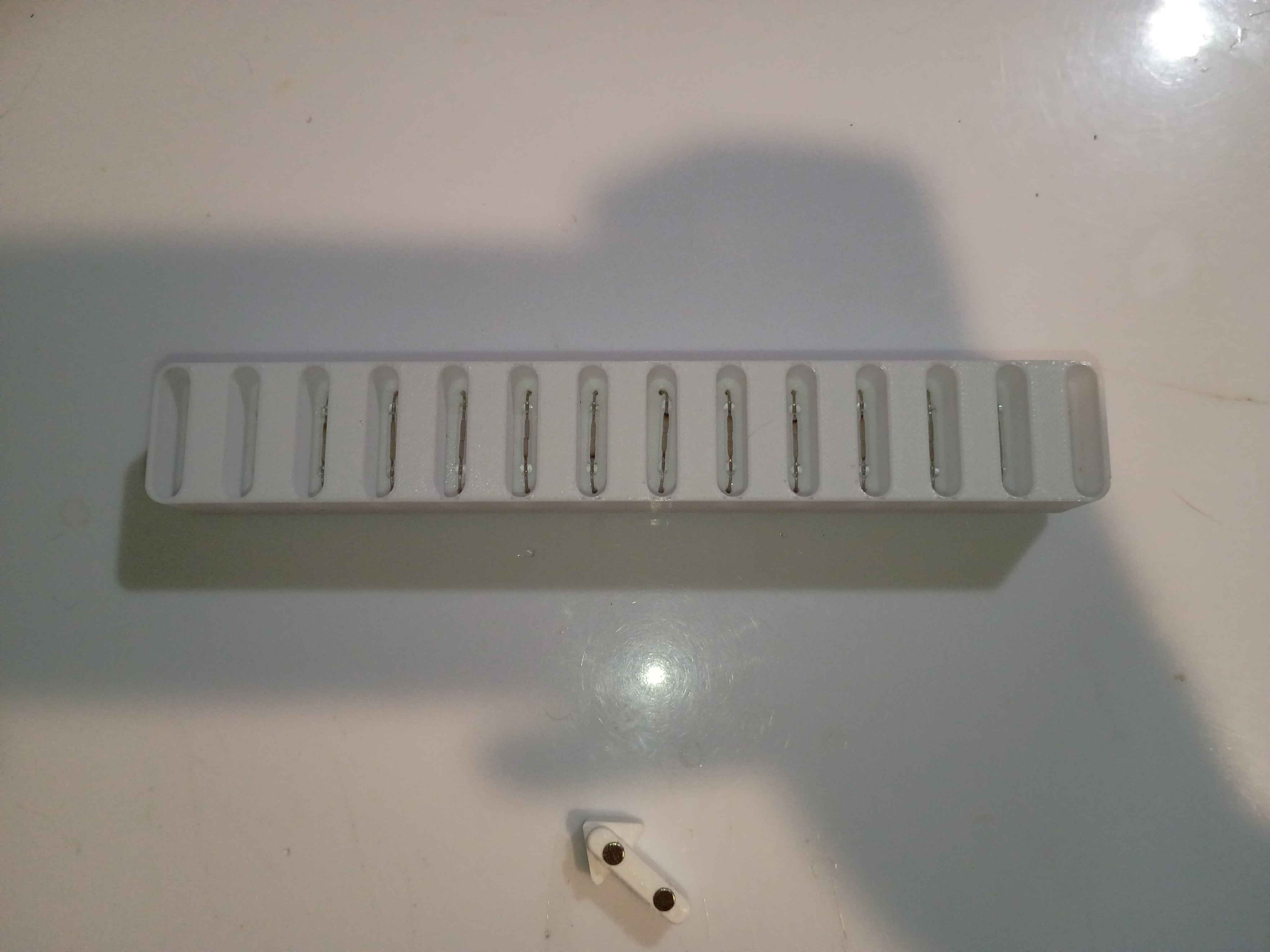
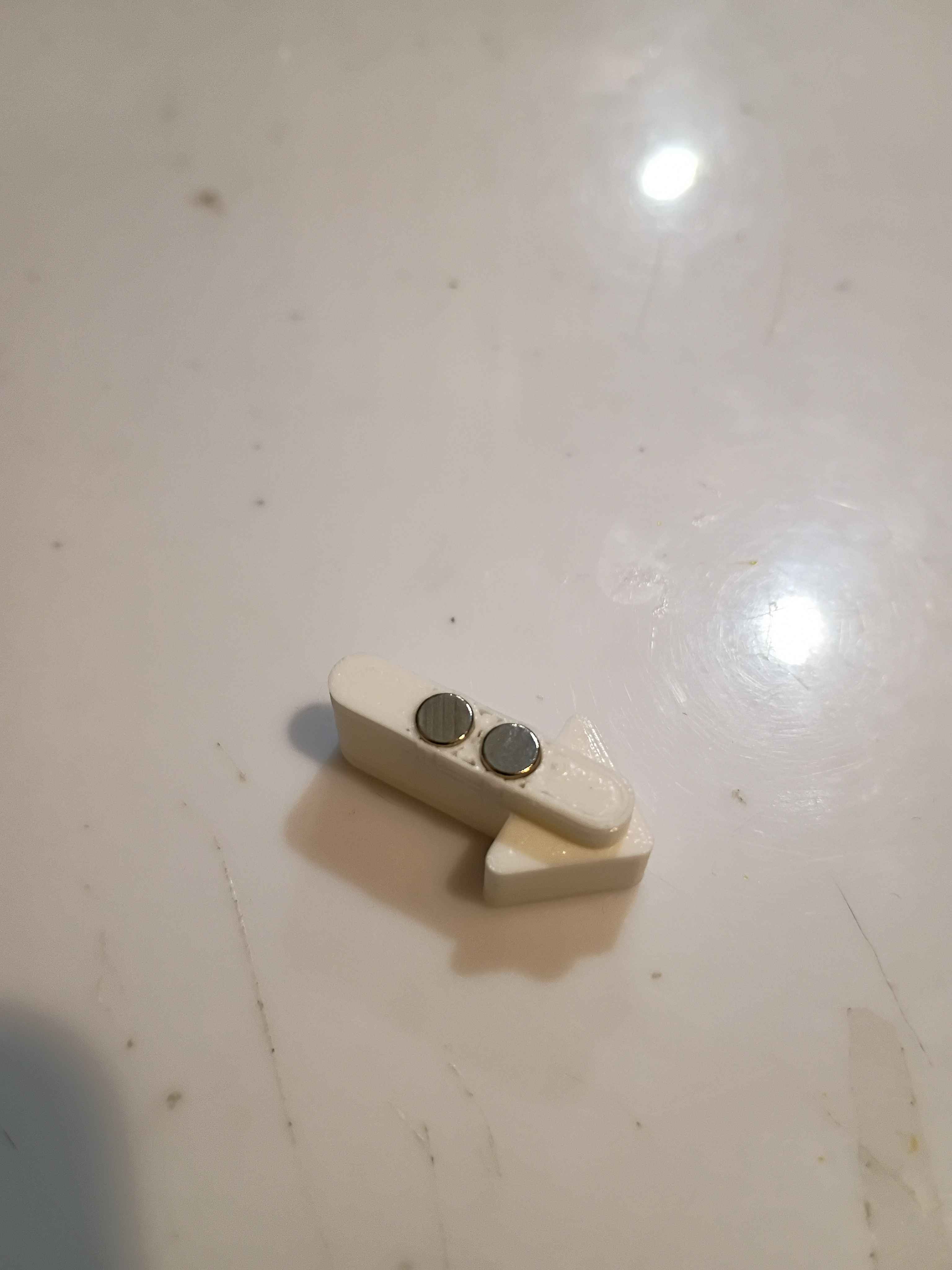
Tested enough configurations of the reed switch to understand the ideal part orientation. Ideally two opposite magnets should be oriented into the ends of the glass tube, perpendicularly, and the flat faces of the reeds should also be facing the magnets. Updated the 03010-006 input device to handle this new spacing and printed for a successful test. Also because this configuration is so sensitive, to prevent false positives, I updated the 03010-003 input slot component to recess the reed switches 5mm lower down. That updated CAD file is uploaded for printing tomorrow.
Received capacitors in mail. Drilled holes in circuit board and soldered caps and LED. Confirmed the LED is mounted correctly. Now we are just waiting for the IC and FireWire socket to be delivered. 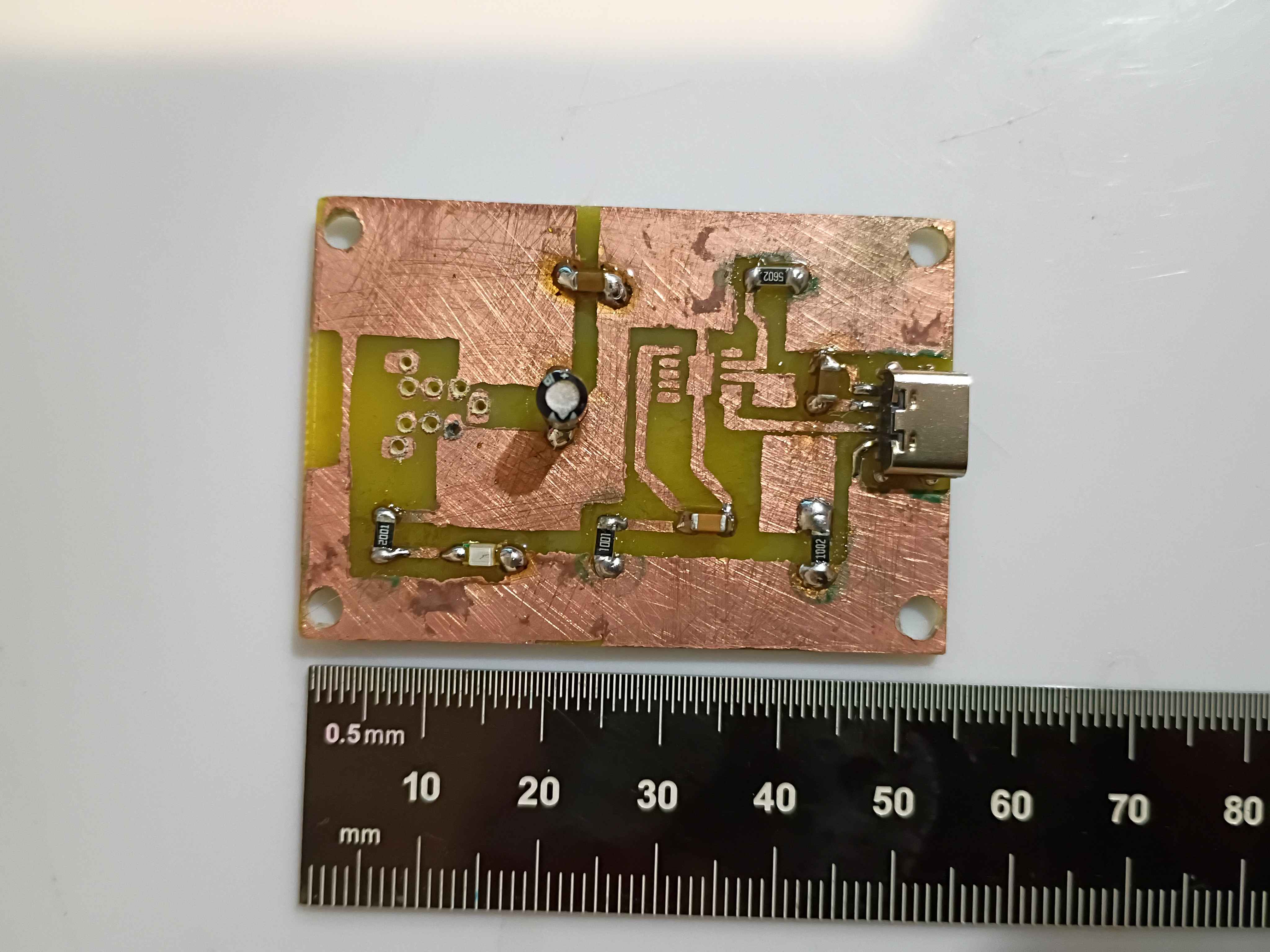
Reprinted box components and reinstalled heat set inserts. Drilled 0.6mm holes in etched PCB. Tested some configurations for the reed switches. 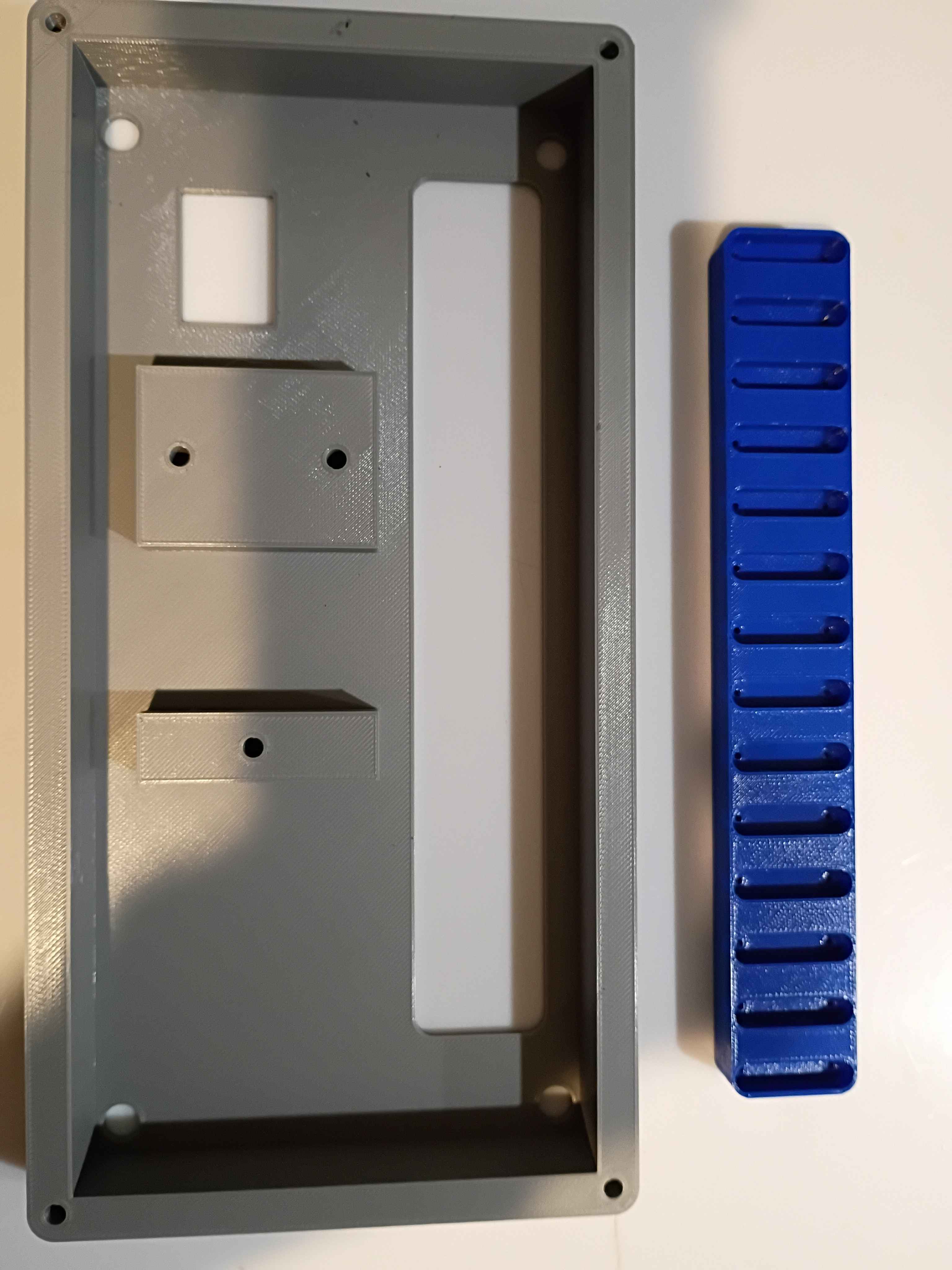
Added feature to Mary-Bot that shows you a rendered preview of your article as soon as you post it. No need to wait for a full website regeneration. Also, the !regeneratewebsite is now faster because it doesn't recreate every single image thumbnail, only the text. There is a new command: !fullregeneratewebsite, which is basically the old !regeneratewebsite. I also added a slight amount of security to the !deletejournal command, to prevent slip-ups.
Updated .3mf files in GitHub repo for printing at work tomorrow on the large format printers. Updated and printed the input device to accept an 1/8-inch dowel for a handle, among other slight adjustments. 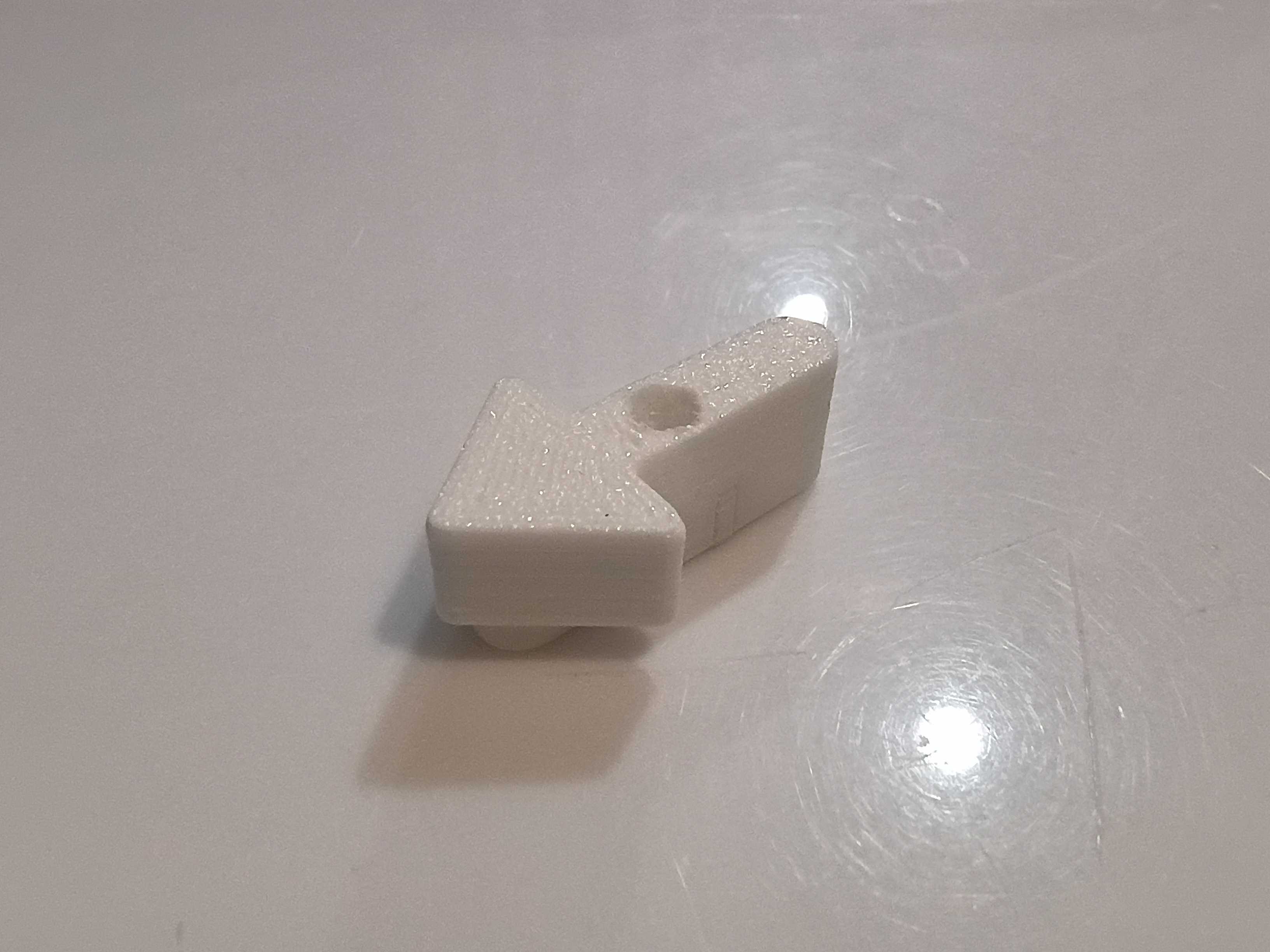
Filed off burrs and soldered components to one of the stepper motor driver PCBs. I oriented the screw terminals in a consistent way for easy wire installation, but that does technically deviate from the schematic. 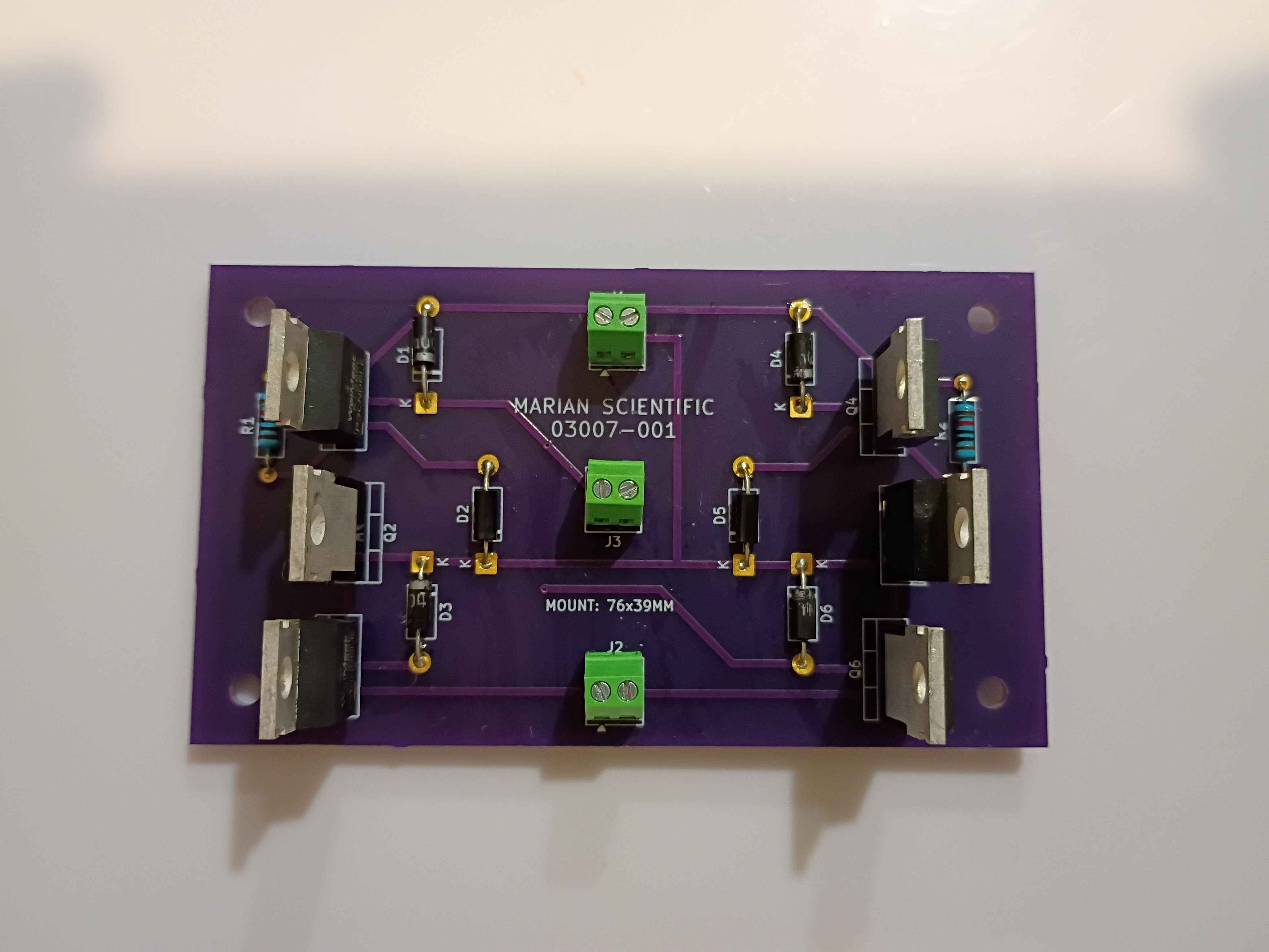
Designed and printed a (very small) magnetic input device. After some preliminary test fits, I decided that the slots in the slotted reed switch assembly needed to be slightly wider, so the entire assembly was redesigned and will be printed at work this week. 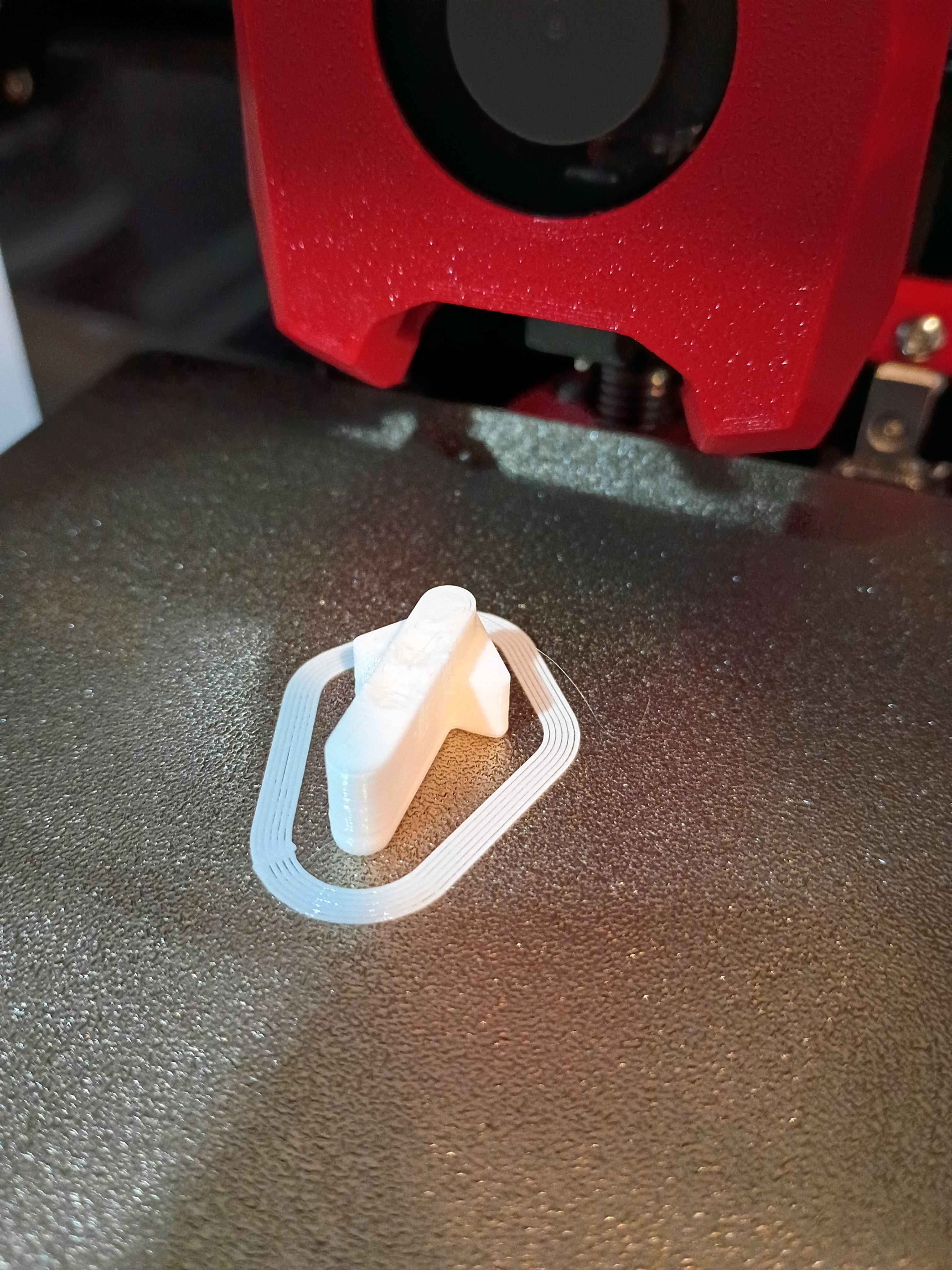
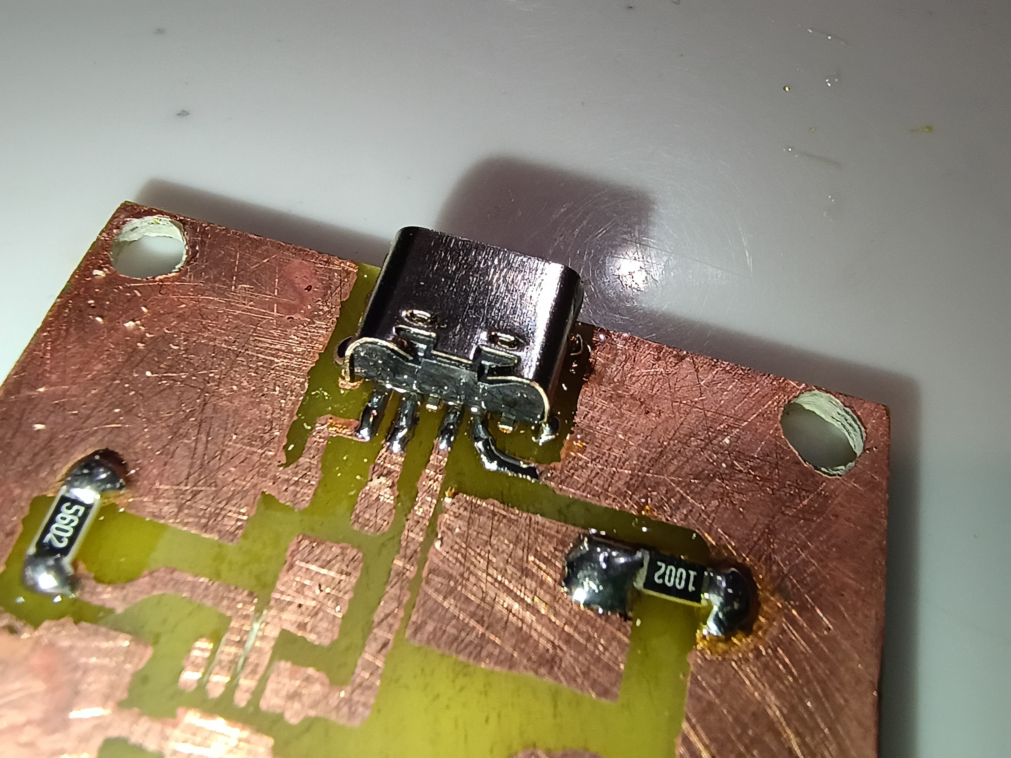
Reviewed the box assembly and PCB designs for manufacturing considerations and provided feedback to the designers. Incorporated the manufacturing feedback into the box assembly. Soldered SMD resistors and USB-C connector (required 1.0 mm holes drilled) to the test board. Purchased ASA filament for the eventual final box print and the necessary capacitors for the circuit. 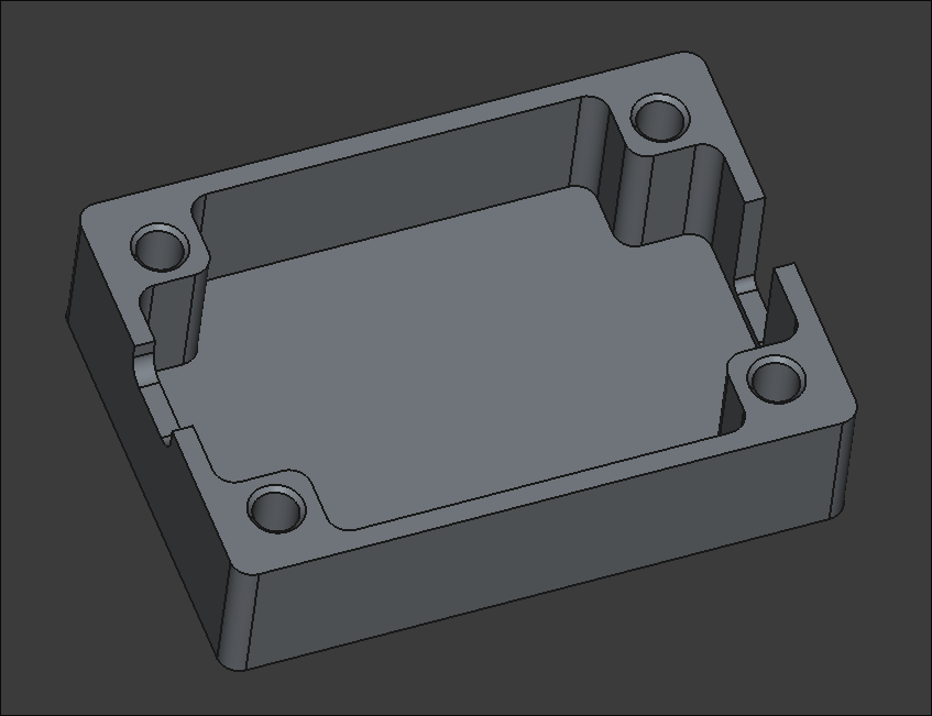
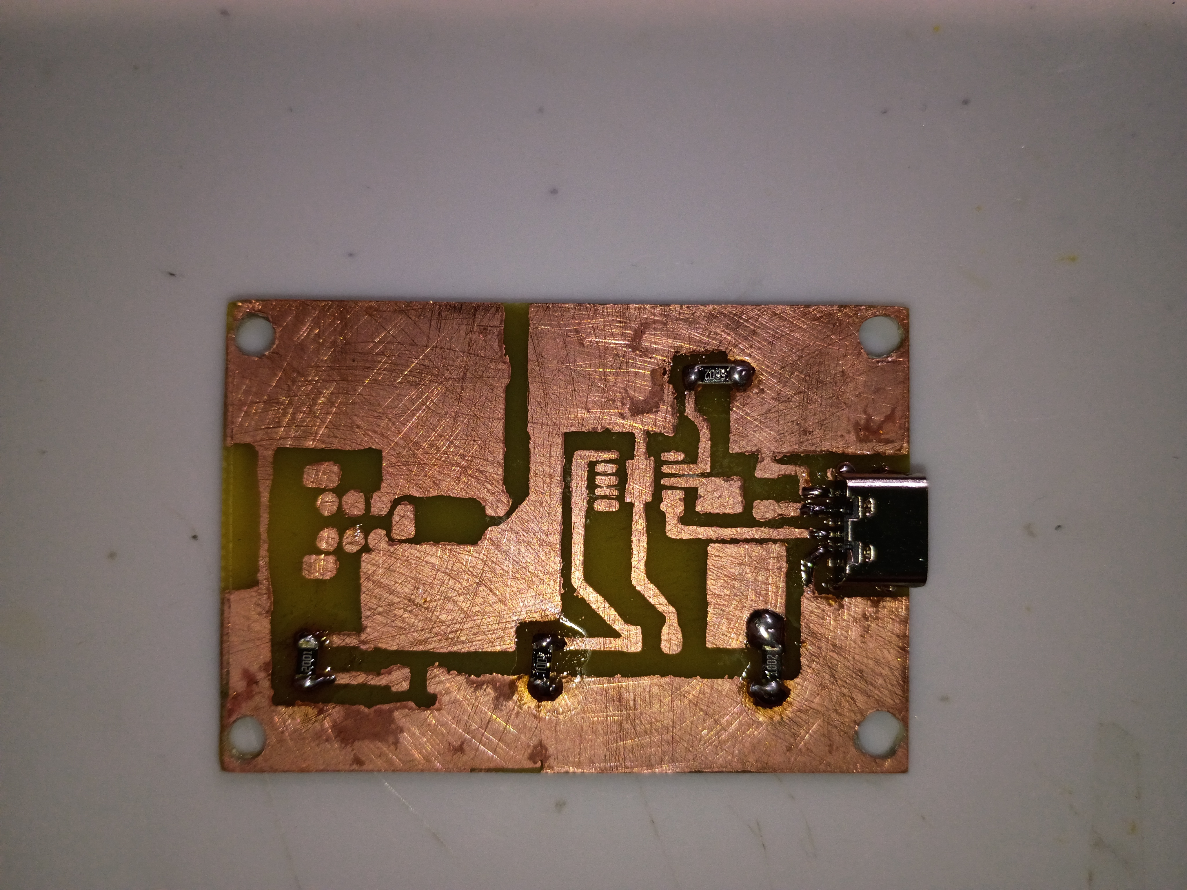
Fabricated the preliminary base PCB, while demonstrating to Anthony. Holes were drilled for assembly. On the next iteration, the copper pours on the mask should be exactly sized to the edge cuts, the hole patterns should be brought onwards roughly 1mm in every direction, if possible, and the box assembly should allow for an extra 0.5mm of tolerance around the board edge. That being said, this assembly will serve as a testbed for the circuit when all components arrive. 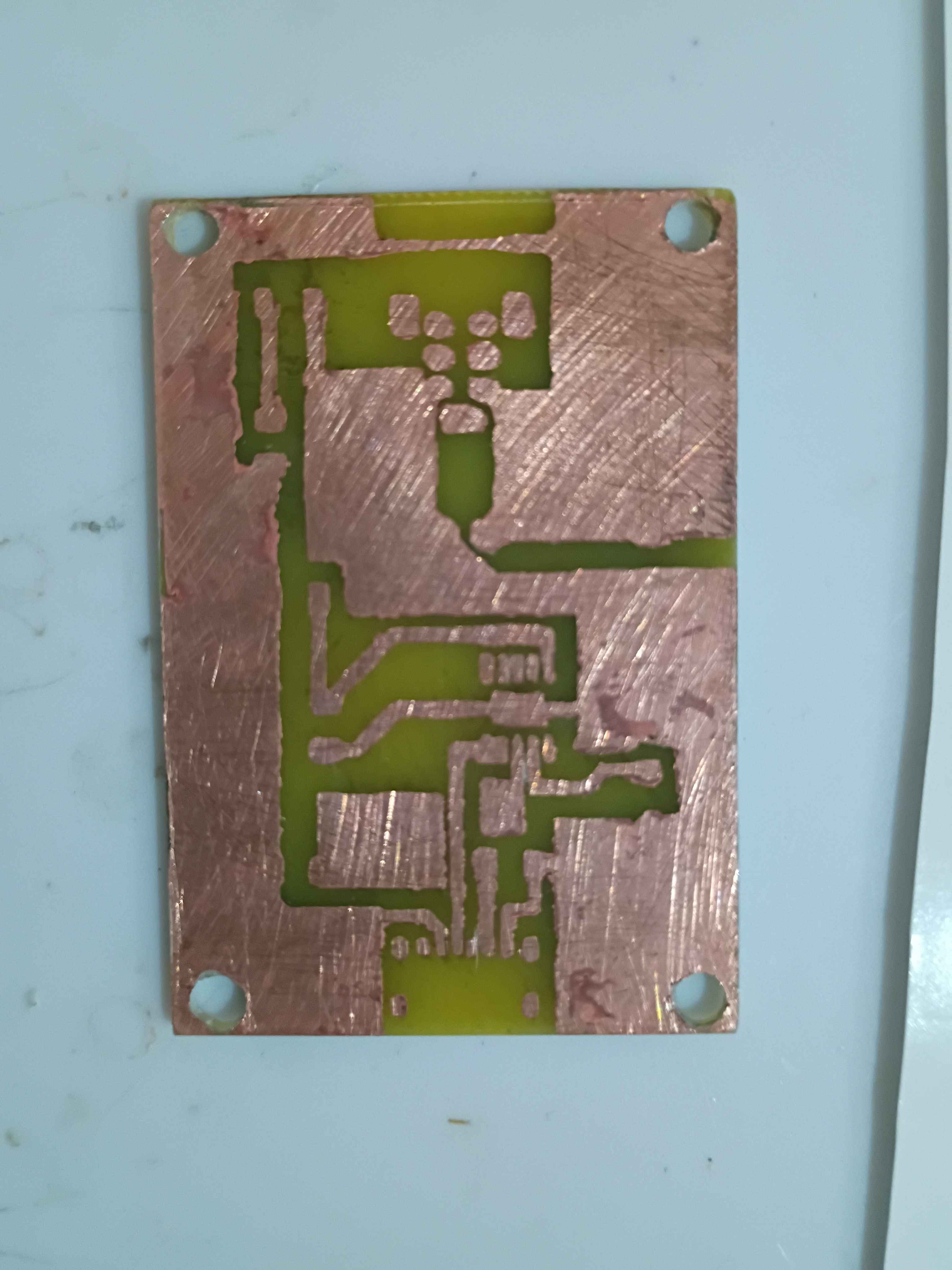
Consulted on the PCB layout and mocked up a draft two-piece box assembly with notional slots for the connectors. Sliced and launched a test print on the new facility Voron 0.2r1 printer using PLA. Assembly will take 4x 3x4x5 M3 heat-set inserts for M3 socket head screws that clamp everything together at once. 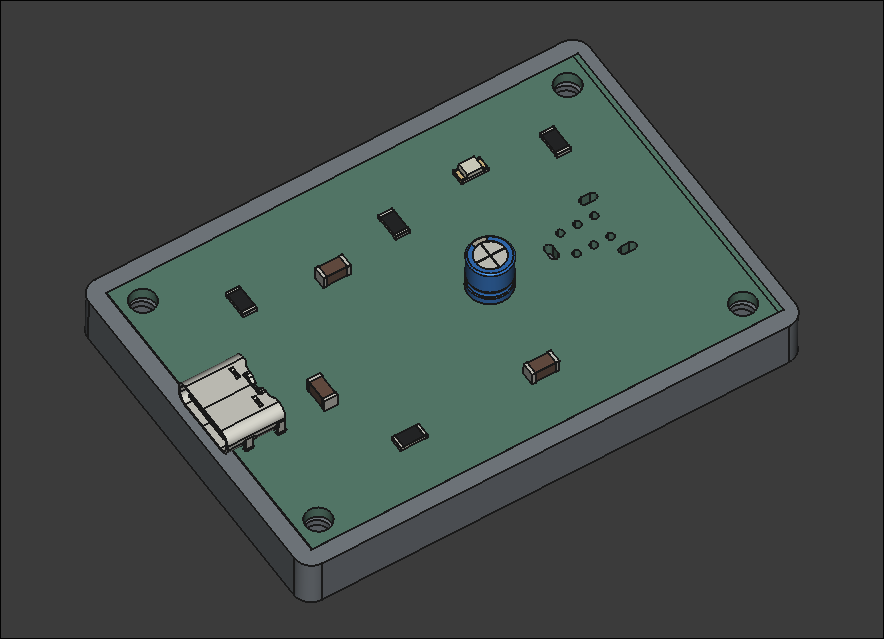
Essentially completed the Voron v0.2 build. OLED display works, wire management reasonable, back panel and top hat installed, spare parts stored away, workspace cleaned, configuration mostly set up. Several test prints completed successfully. More fine tuning will come in time, but this seems way more reliable for my purposes than my old Ender 3 V2. Props goes out to the Voron developers for this. Inspires me to make a more barebones version with a much shallower Z-depth and fewer components in general. See video of it in action. 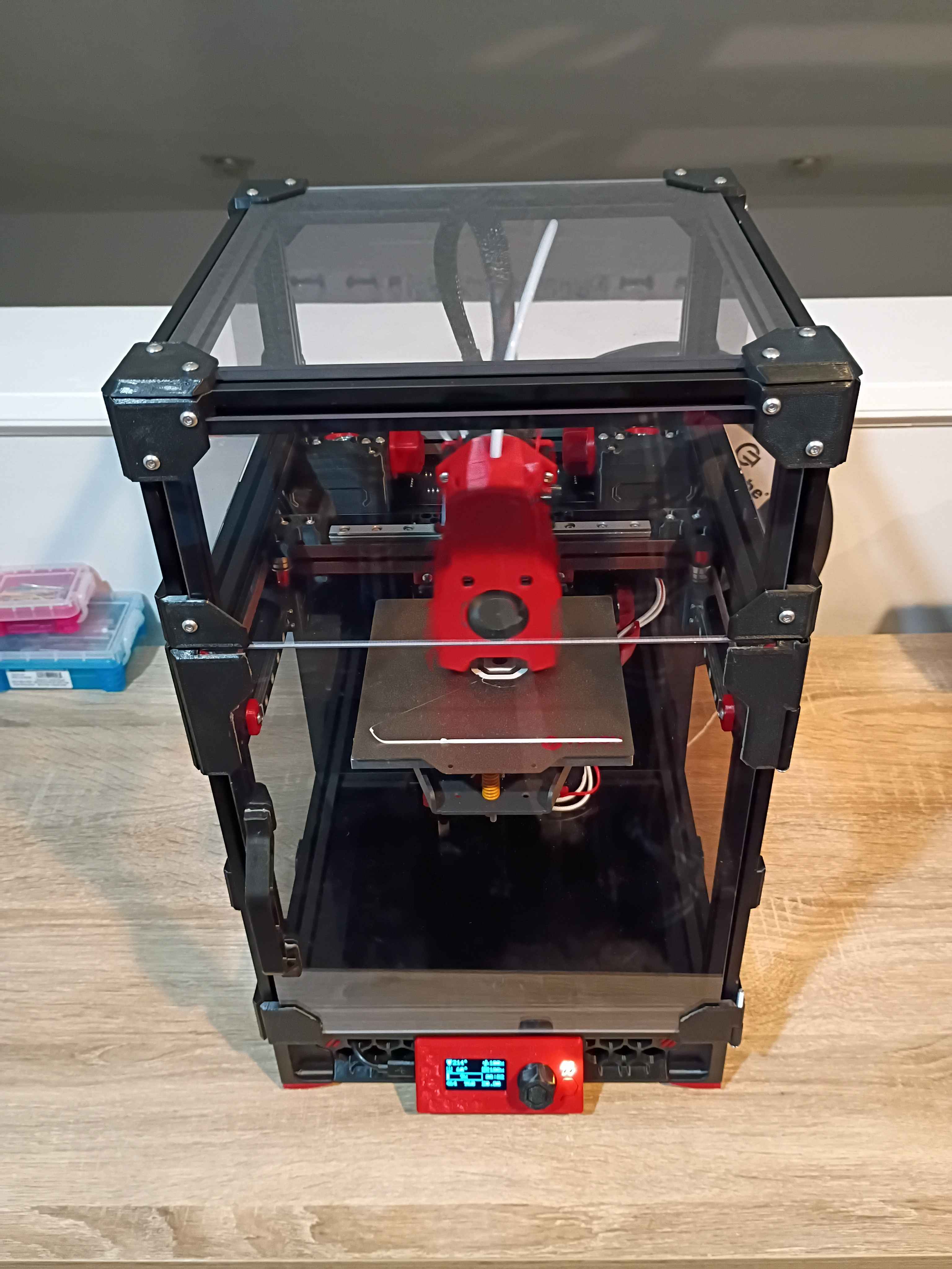
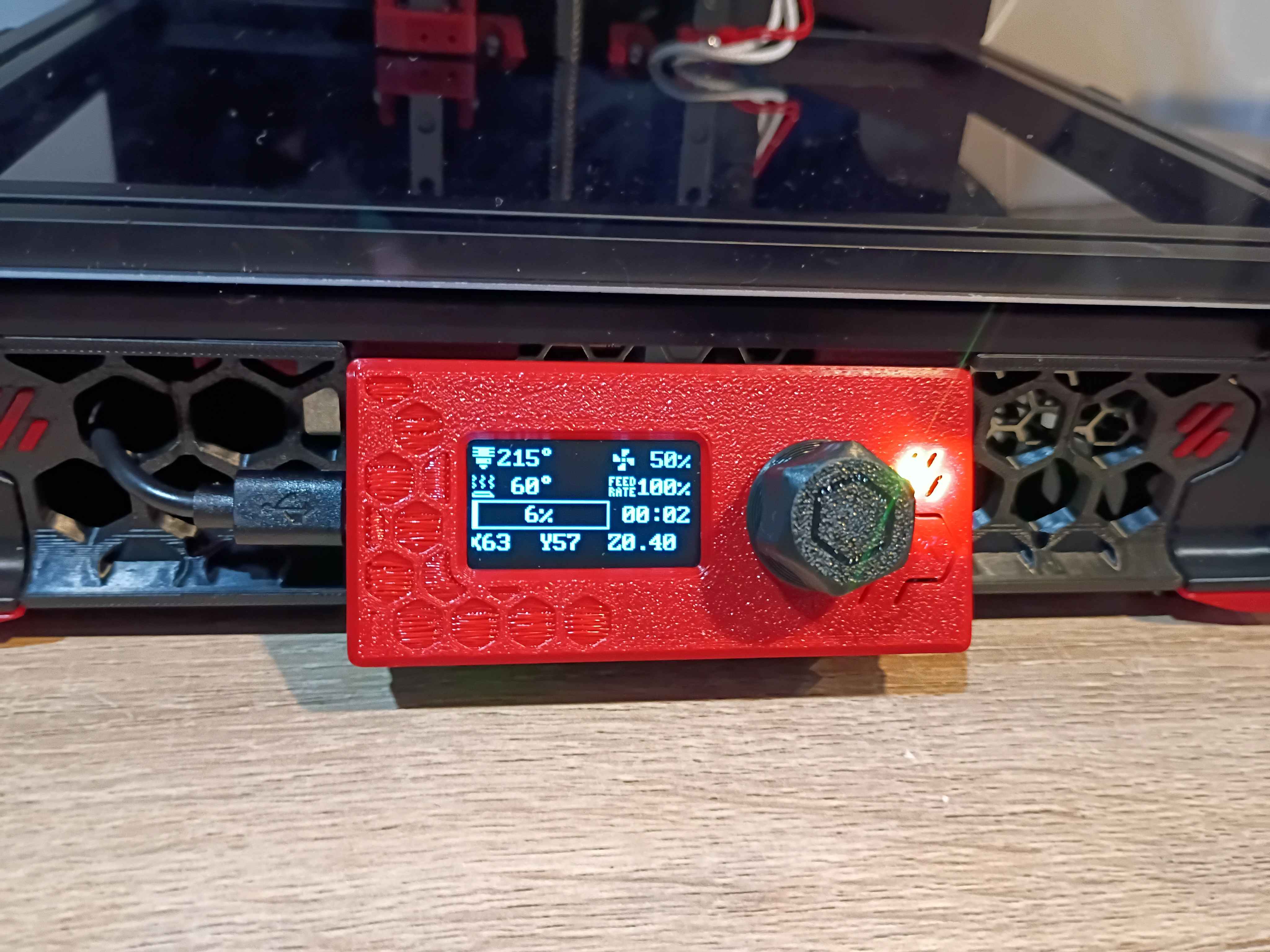
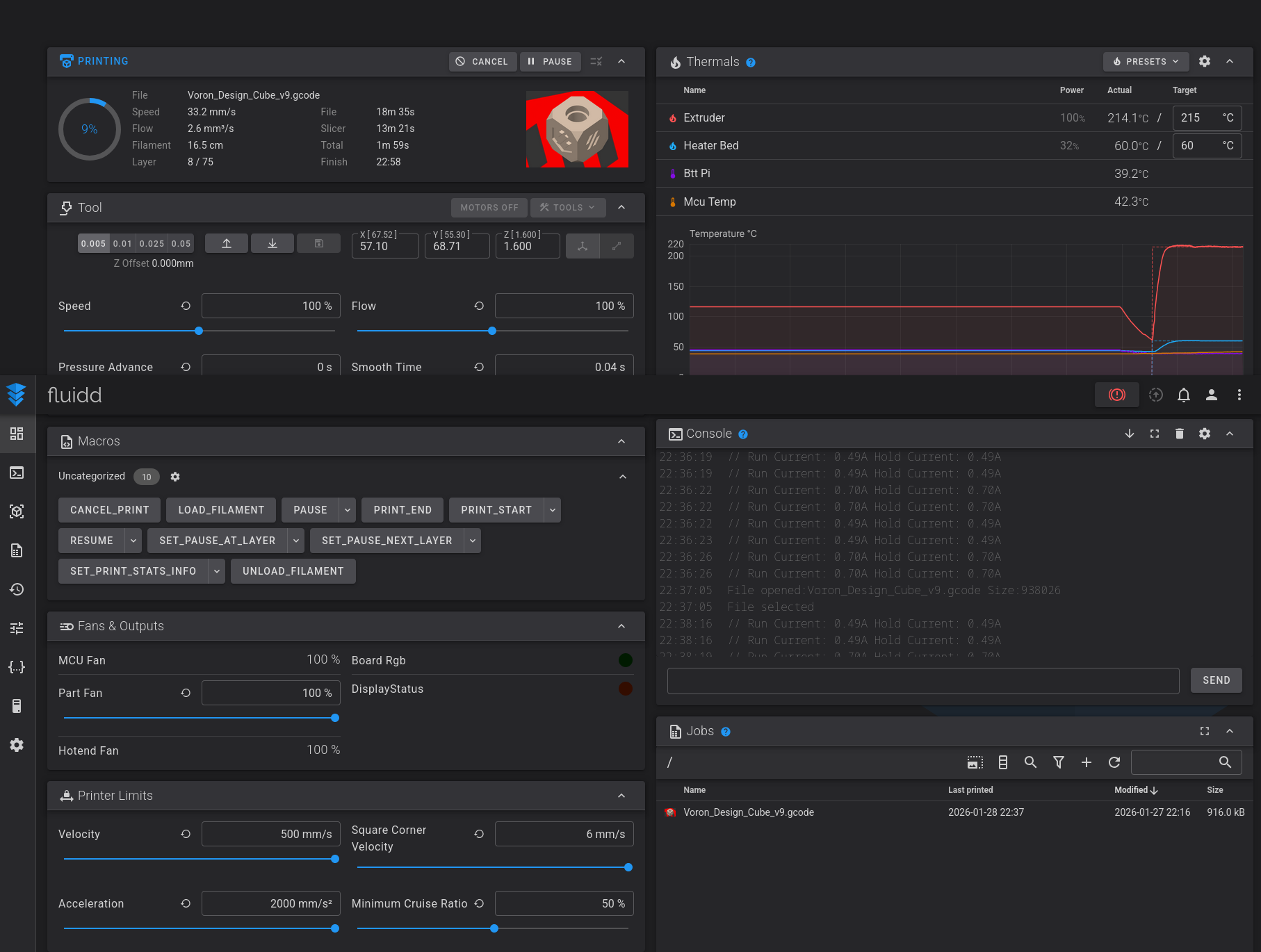
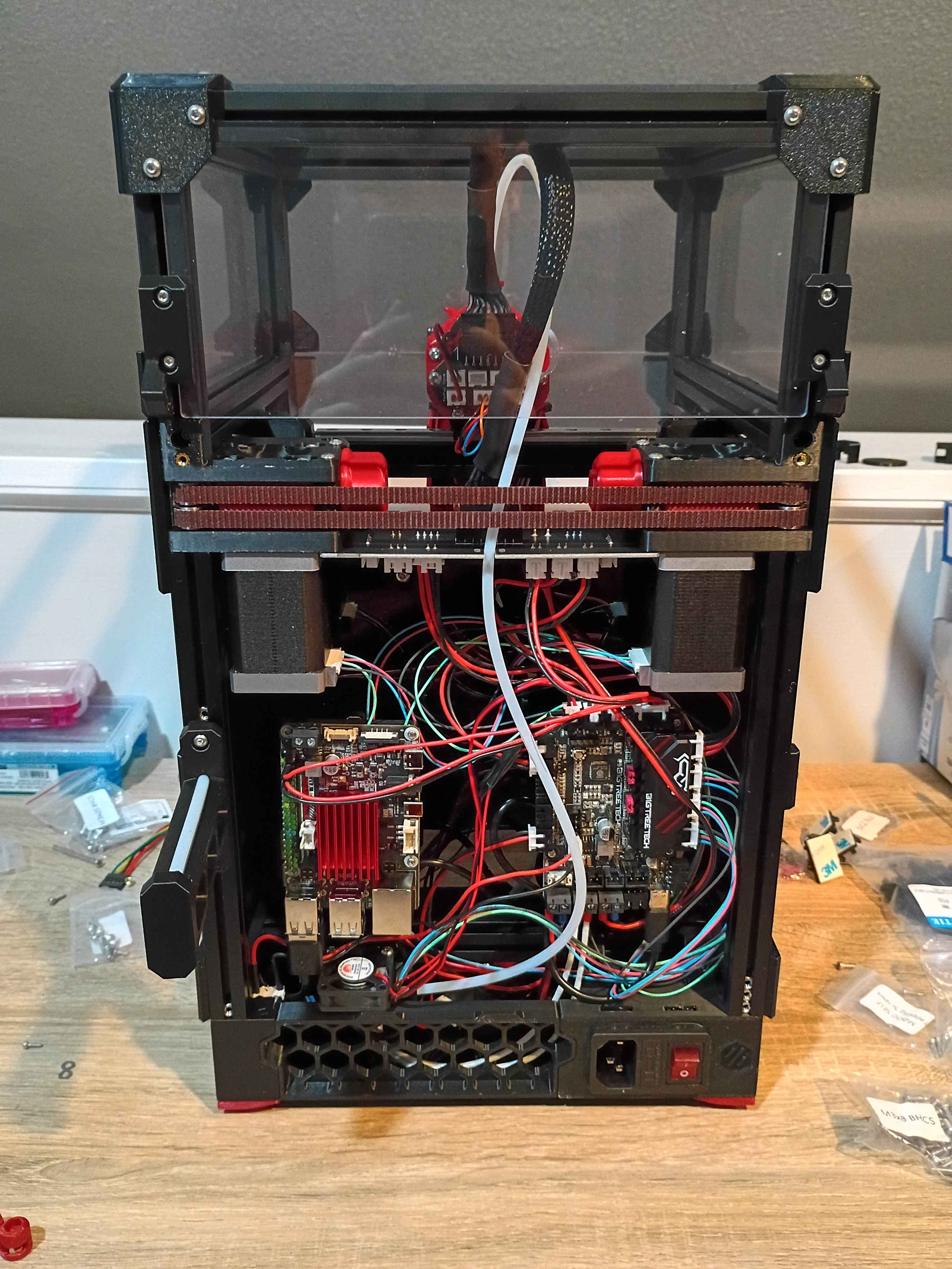
Fixed some minor electrical and software issues on the Voron v0.2 and got it printing successfully! The main issue with the electronics was that 2 sets of 2 wires were mislabeled, so I was sending negative 24V to the part cooling fans and negative 24V to the extruder fan. Found the issue, swapped them around, and it was fixed. Spent some time tuning config parameters and leveling the bed. Now that it works, tomorrow I can enclose the electronics and wrap up the build. Also the OLED display needs to be properly connected and configured - right now it only shows some default sample text. I think I'll also clean up the wiring slightly and eventually get some kind of air filter system to print ABS, though that can wait. 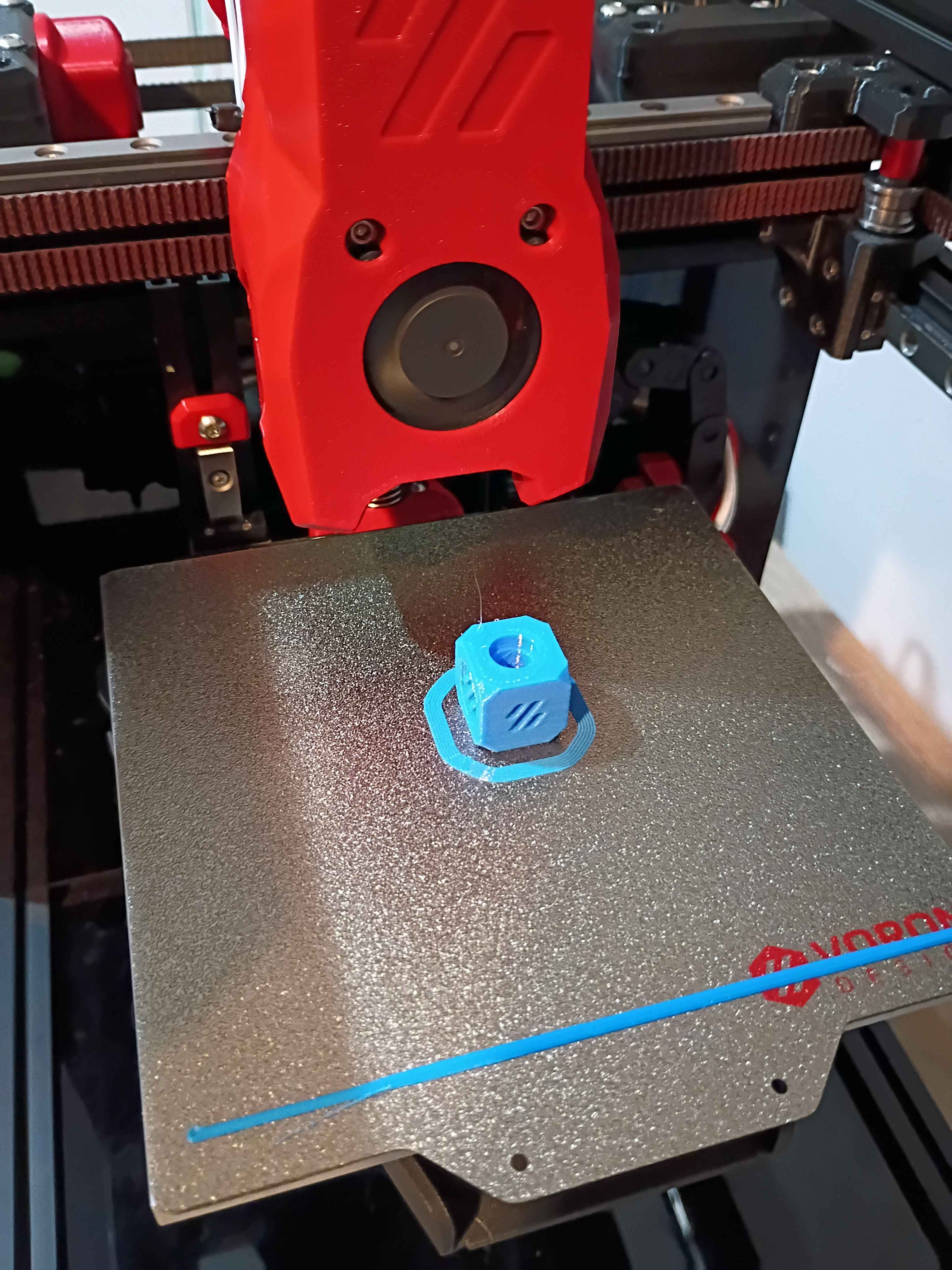
Helped launch project by brainstorming solutions to client request, conducting research, purchasing necessary components, and assisting with preliminary draft circuit schematic and PCB layout. 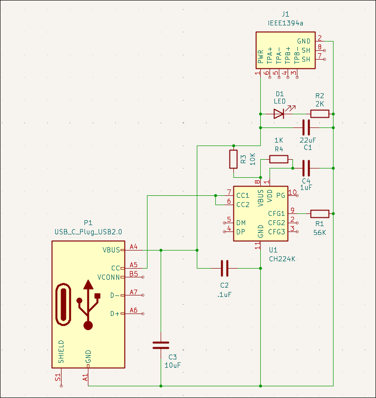
Continued to set up firmware for the Voron v0.2. Have the OS set up, and I'm just working to get the SKR Pico and OLED screen connected successfully.
Wrapped up most of the Voron 0.2 r1 build. The only thing remaining is the back panel cover (and hinge for the top hat) because I am hesitant to believe I wired (guessed) all the electronics correctly, and you can only access them from the back. Once I have the software set up and can validate that the electronics works, I will wrap up the final few operations. Also, although it's not necessary, I'd like to add more screws to the z-axis linear rails and upgrade the part cooling fans if not the entire hot-end system, but those can wait until after the printer is working and mostly tuned in, likely later this week. 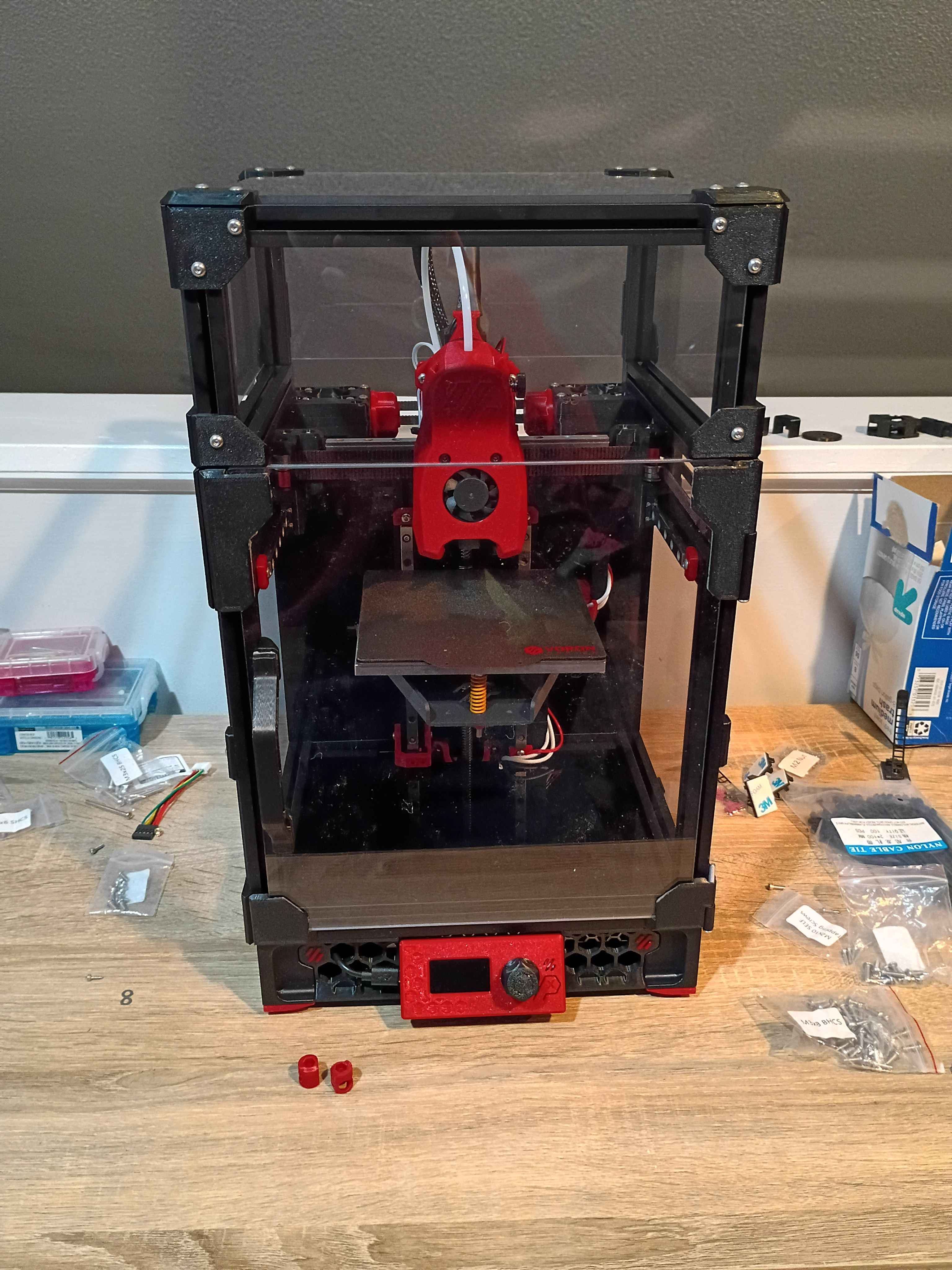
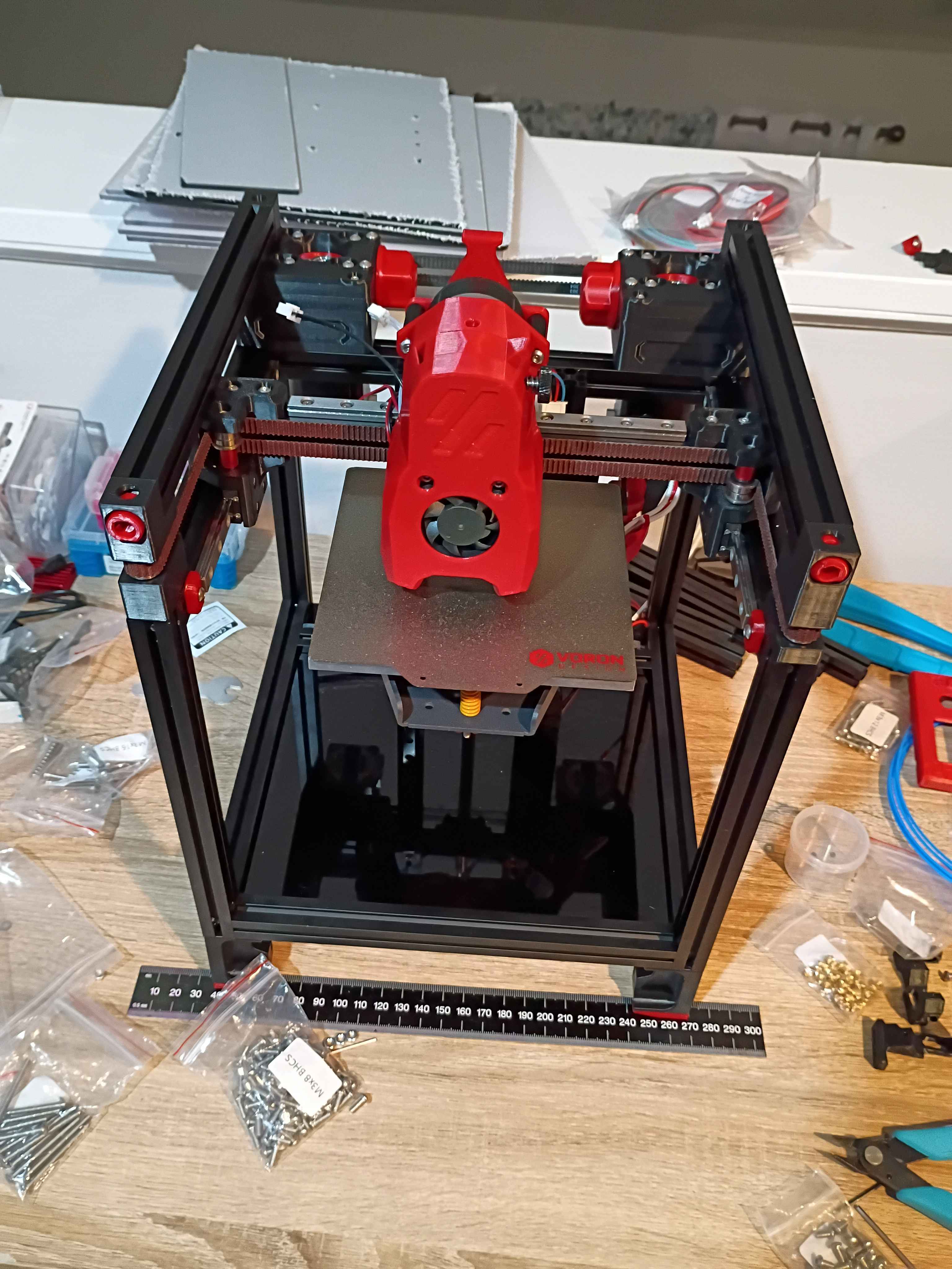
Continued to work on the Voron 0.2r1 kit. Completed most of the frame, motion system, and toolhead. Probably only 1 more day. 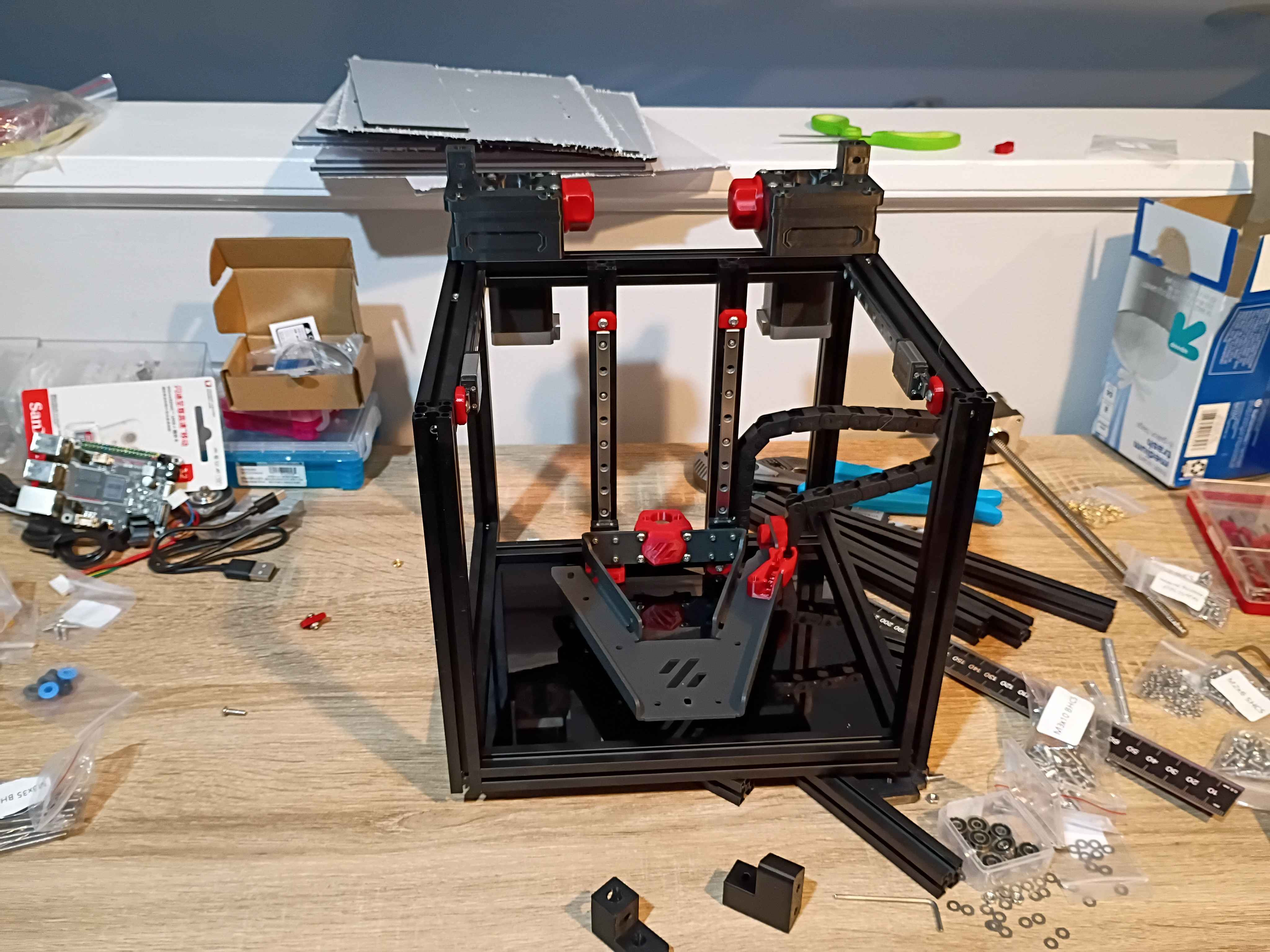
Started kit build of Voron 0.2r1. 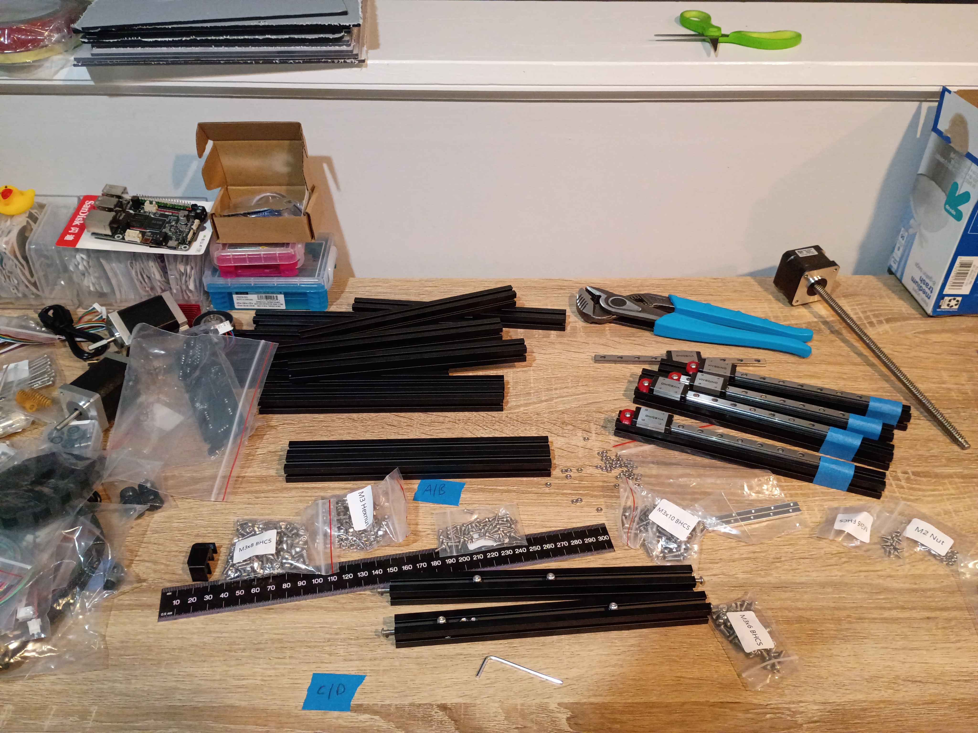
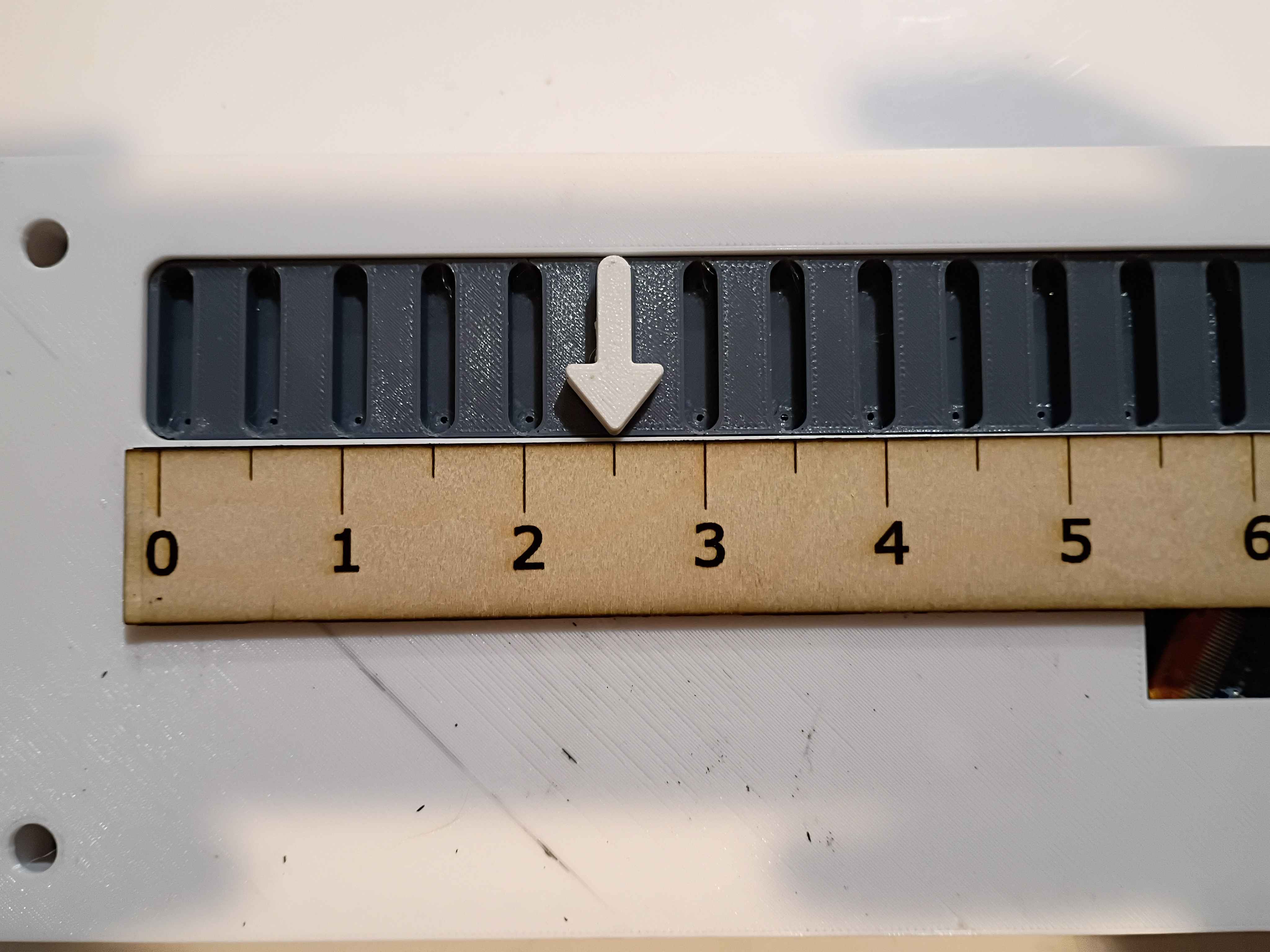
Laser cut some 03010-001 rulers. 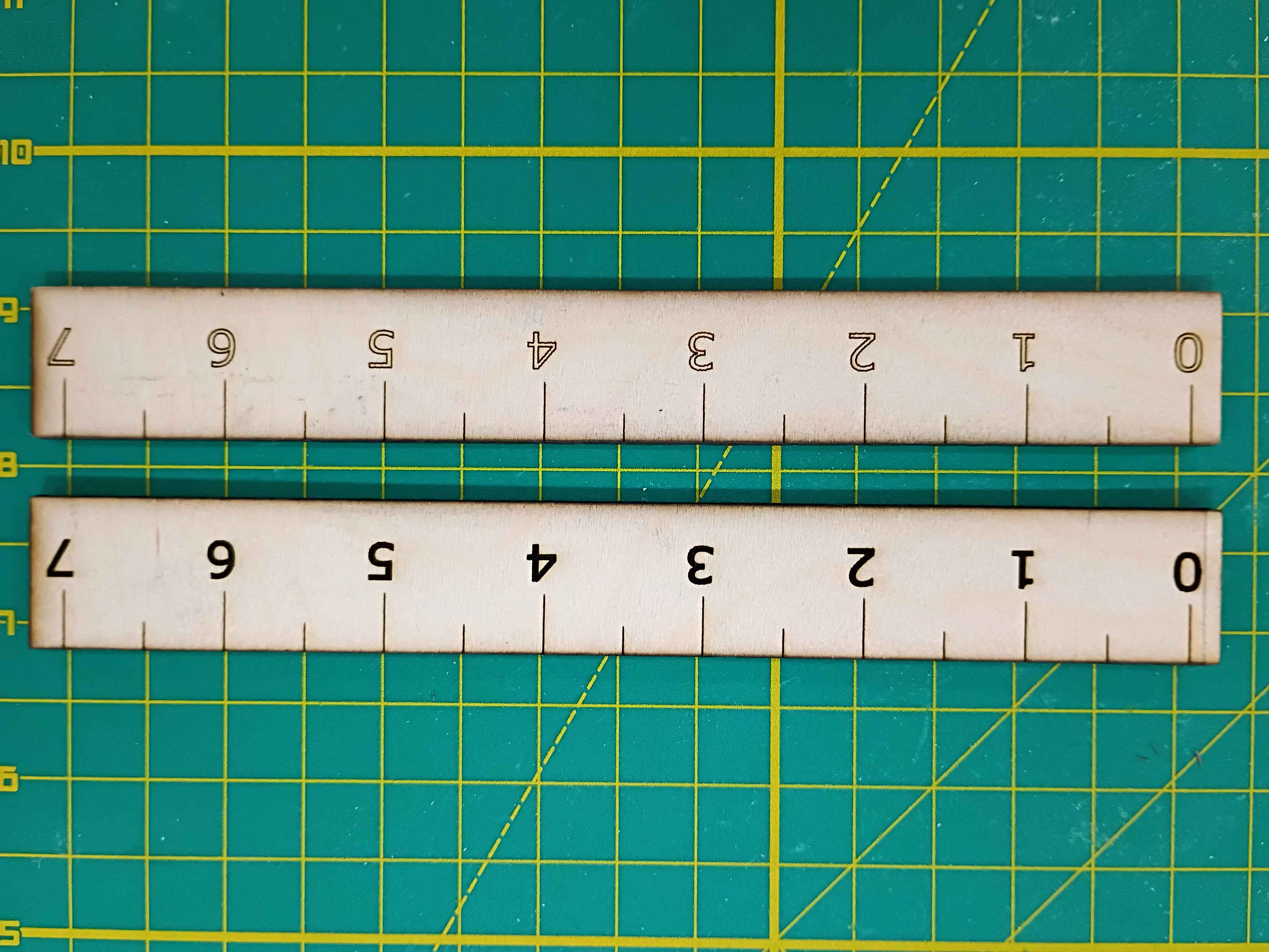
Tested box layout. May need to reprint the white body piece with the OLED cutout slightly lower. 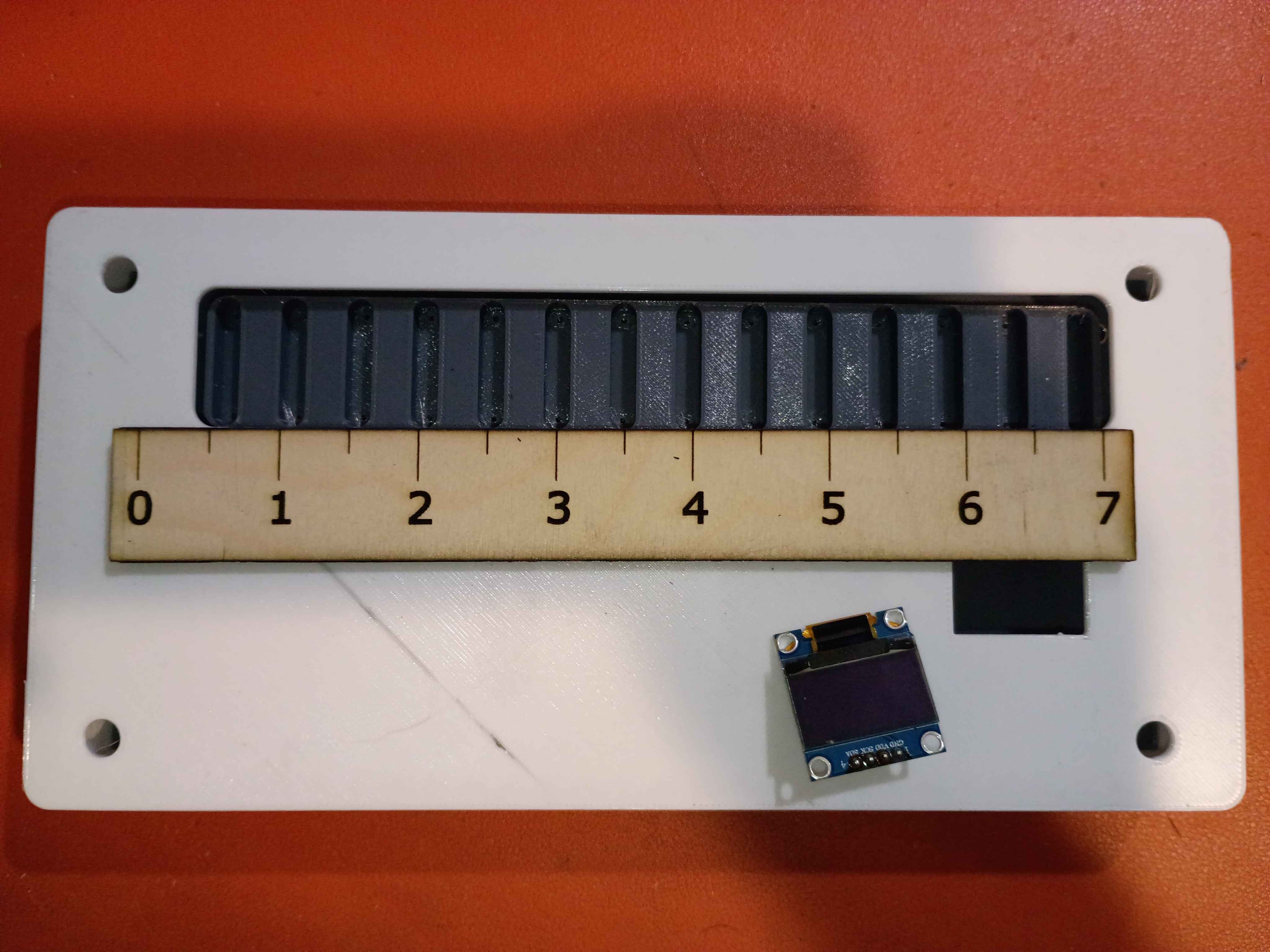
Attached rubber feet to bottom. 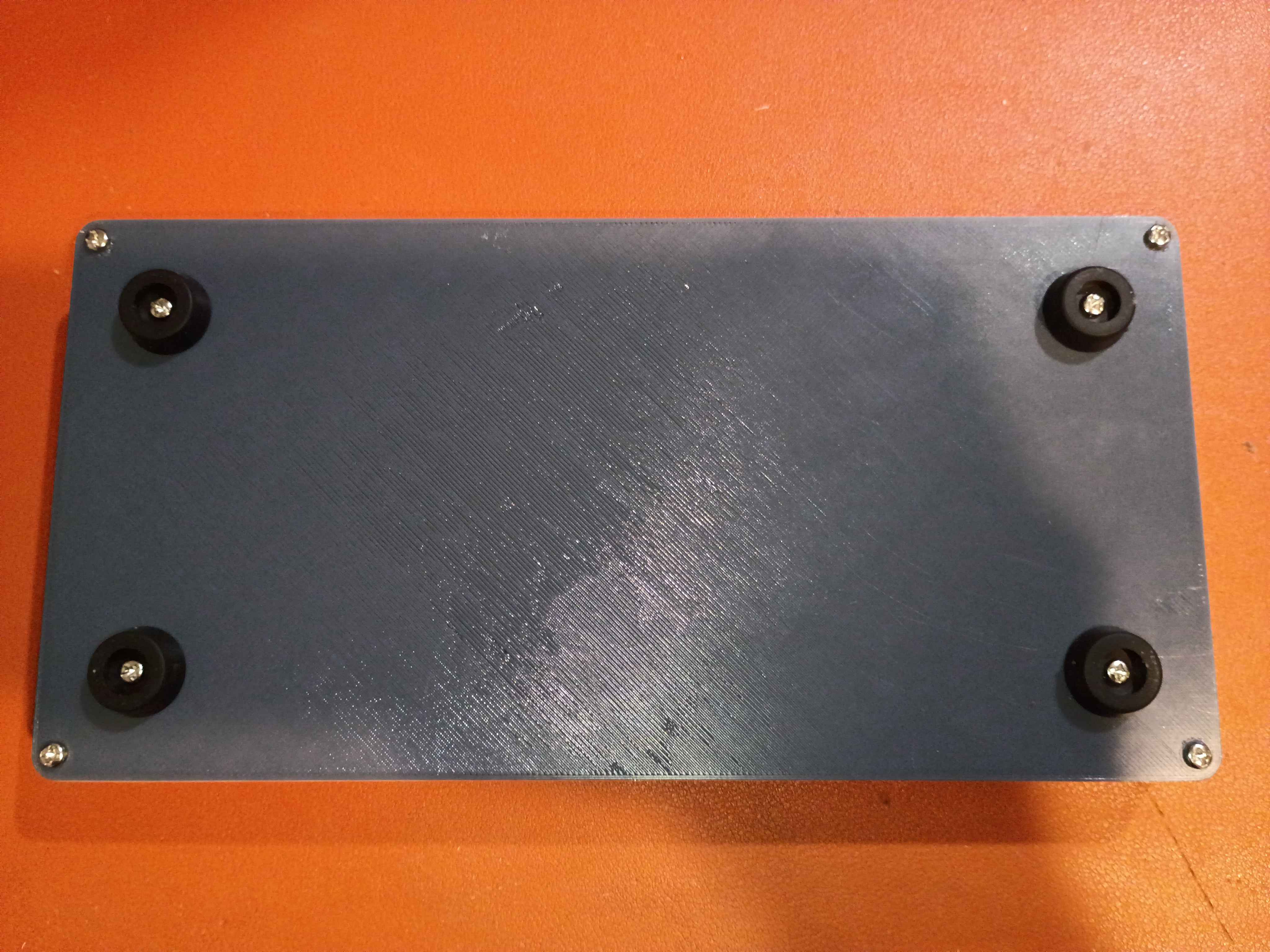
Tested various Ferric Chloride etch-resist options on a scrap piece of copper clad. 
The finest and best solution is multiple coats/layers of the Ultra Fine Sharpie, or masking tape for large rectangular areas. 
Used these solutions to repair minor issues in the toner-transferred copper mask. 
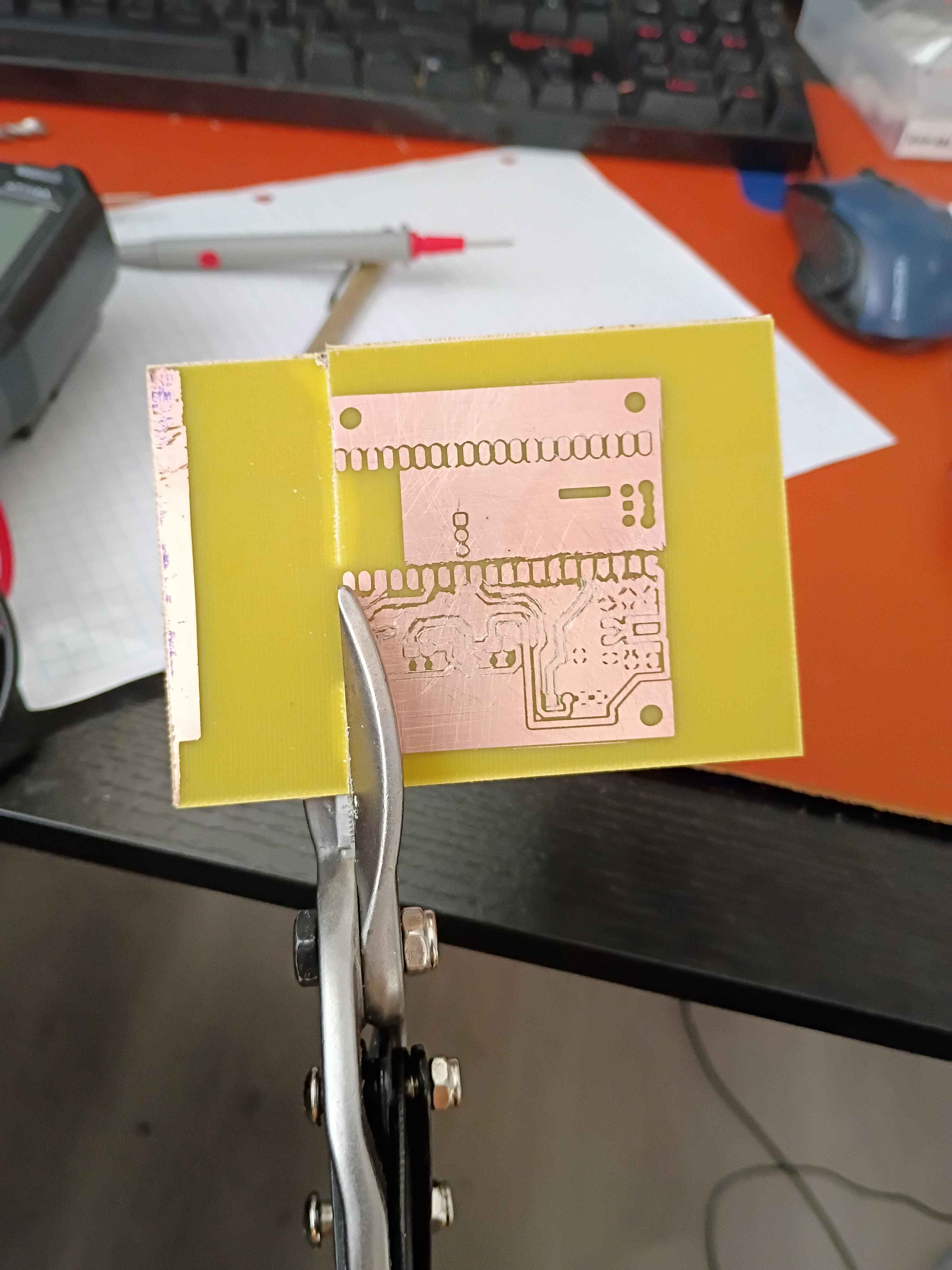
Etched away the copper to reveal the traces. 
Toner-transferred the copper trace mask on the copper clad board. It actually turned out decently for the size and relative complexity. The edges peeled off a bit, but that always happens for me; I will redraw those areas with Sharpie or masking tape. I also scraped off the lingering bits of paper with a knife. For future reference, I used the iron on max heat, let the board cool briefly before setting it in the water, and let it sit in the water for ~20 minutes before rubbing off most of the paper backing, and 20 more minutes before rubbing off any remaining paper residue. 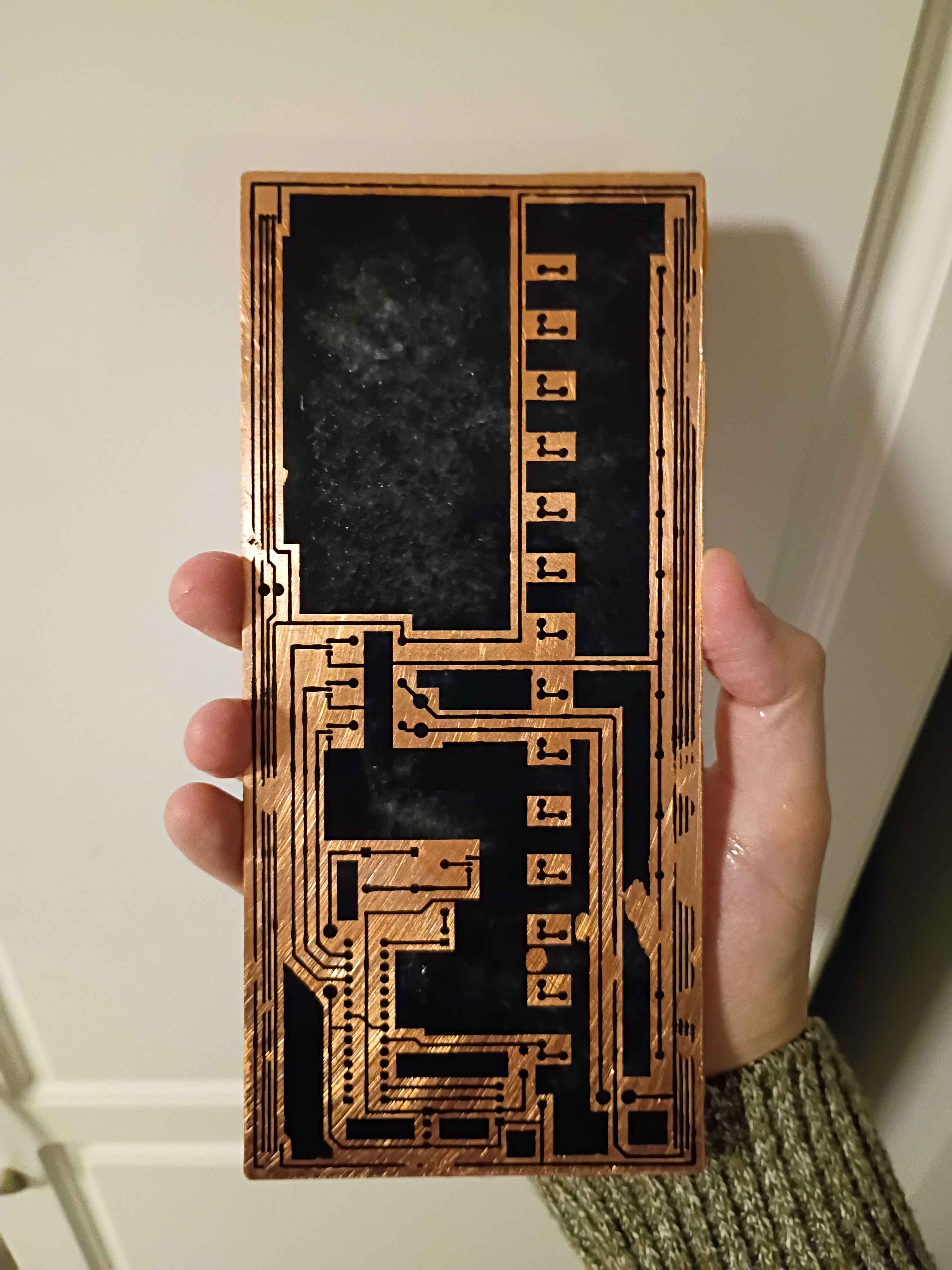
Implemented "!editjournal" command in Mary-Bot to edit an existing journal entry. Date, project & author values are preserved, but text content and uploaded images are replaced completely. Intended to make it easy to fix small grammatical errors or replace pictures. The syntax is: "!editjournal 0094 Revised text content goes here." In fact, this journal entry was created and revised using this command.
Successfully printed the box assembly from PETG. A little bit of warping on the large flat cover piece, though the screws should hold that in place, and a bit of discoloration streak on the top of the main box component, so I may need to sand/paint or cover with a sticker. Everything fits together well. 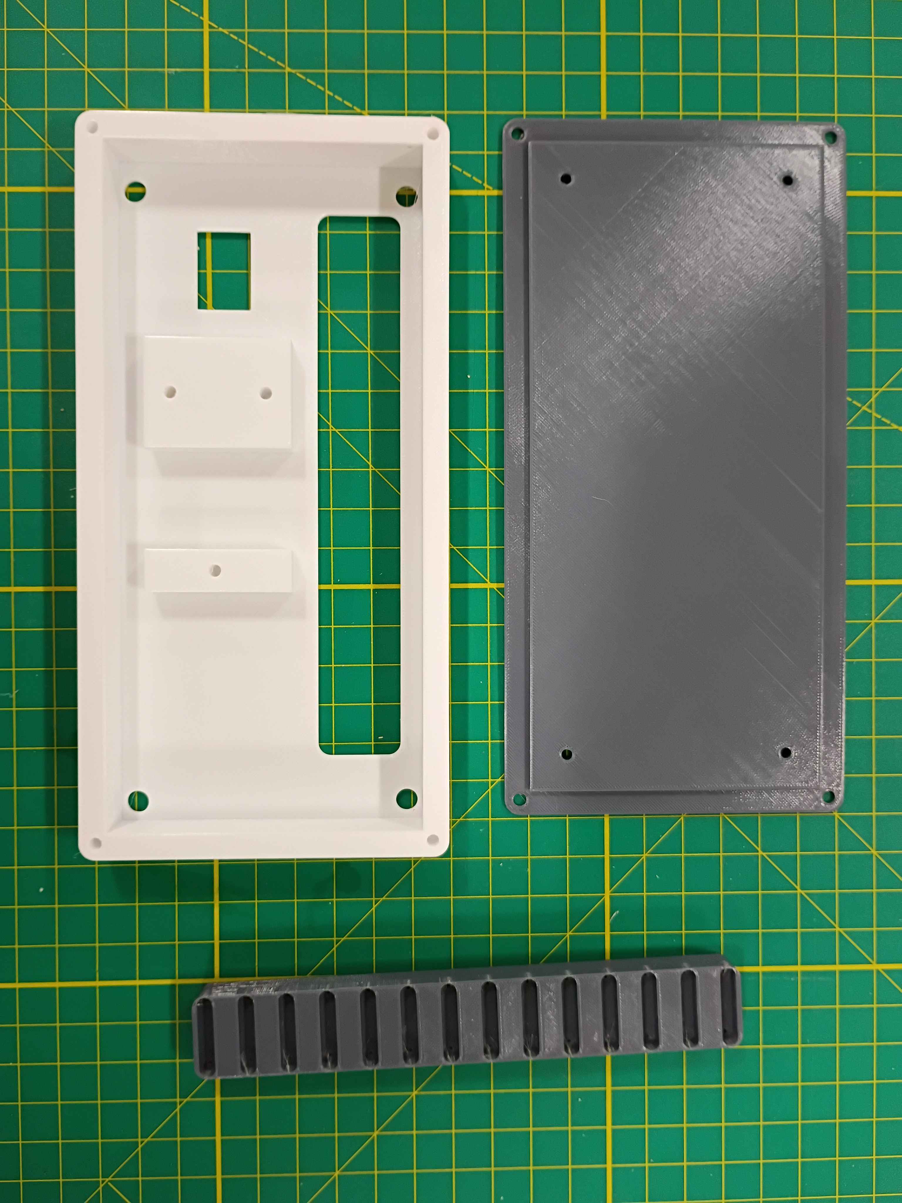
Completed design for a prototype box assembly that should support all the components and the rubber feet I already sourced. Since the part is quite large, it will need to be printed on the machine at work. I will try that tomorrow. I might need to iterate on the main support body at least once to get the depth correct. 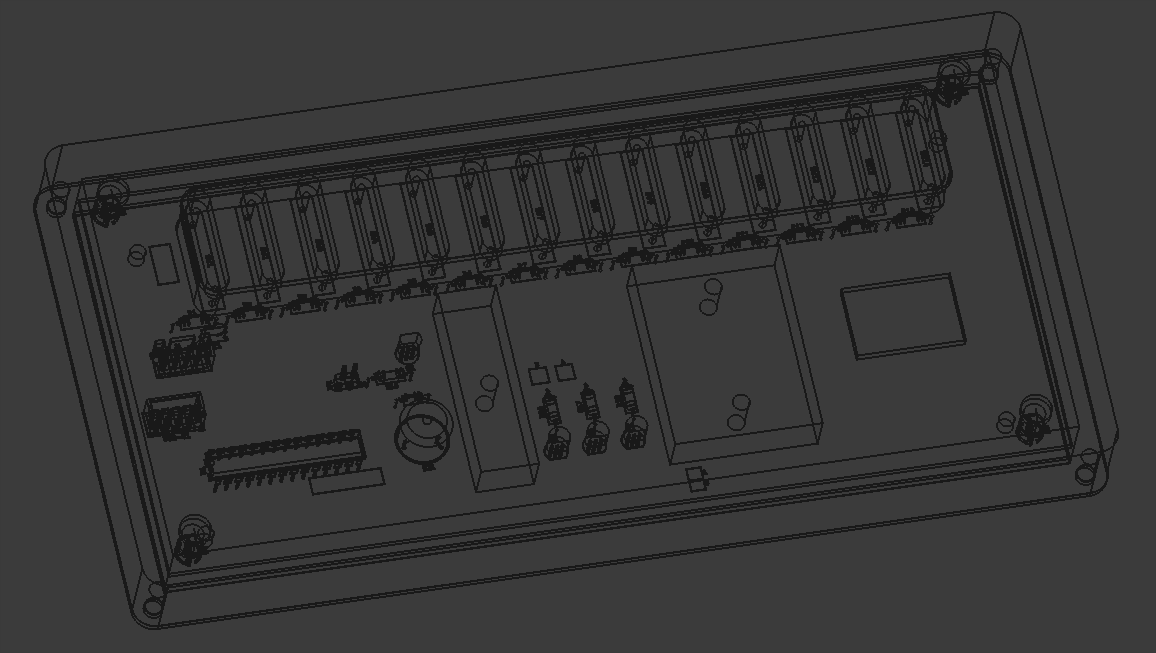
Designed a 3-piece 3D-printed assembly for the project. One component to support the reed switches on the PCB, one box to mount the PCB assembly, and a lid. I still need to add a hole in the top face for the OLED screen. Everything is removably mounted with M3 screws. 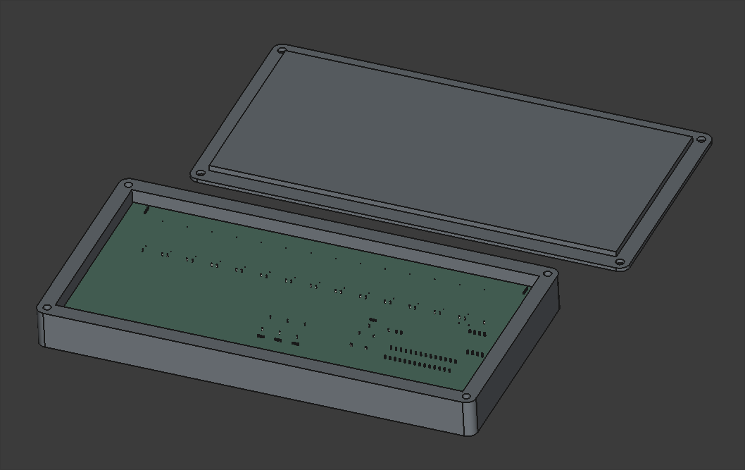
Looking into possibly pivoting away from laser-cut plywood box to a 2-piece 3D-printed box. It would be more robust, reproducible, and suitable for this container, though it will be roughly 230mm wide, which is approaching the maximum for the Prusa MK3S that I will print it on, which may pose problems.
Finalized design of top and front/back of manipulative box. Still considering options for the bottom that are easy to remove for access to repair and replace components.
Continued design of box lid, following the same ridged perimeter profile that worked so well on 03008.
Began the CAD for the box. Imported the PCB STEP file from Kicad to ensure a proper fit.
Added usage instructions and photos to the documentation linked by the product URL.
Trimmed roughly a quarter inch off the end of the ballscrew to make the entire Y-axis motion assembly fit in the frame interior (barely). Installed the stepper motor bracket in the proper location and then installed the stepper itself. Determined that 18mm of shimming will be required below the ballscrew support blocks. I have various aluminum stock thicknesses that together stack up to that value, and I can cut and drill those this week. 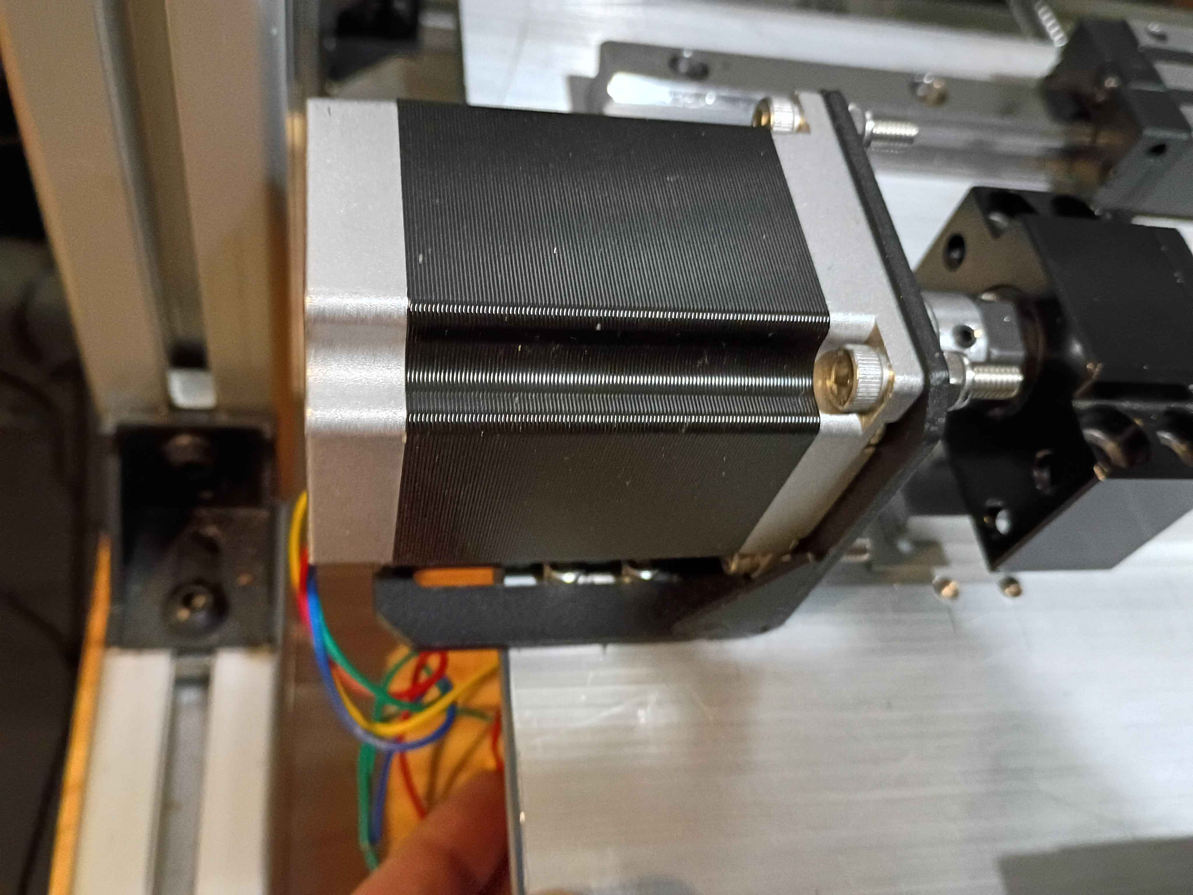
Calculated, measured, marked out, drilled and tapped holes for the Y-axis motion control on the X gantry plate. Installed the linear rails. Because space is tighter than I anticipated, I'll need to saw off a bit from the ballscrew and possibly even some from the drive shaft on the stepper. Not ideal but it should work. I'll also need a different stack of spacers between the ballscrew follower thingamajig and the XY gantry plate since the stepper mount is different, again since space is so tight. 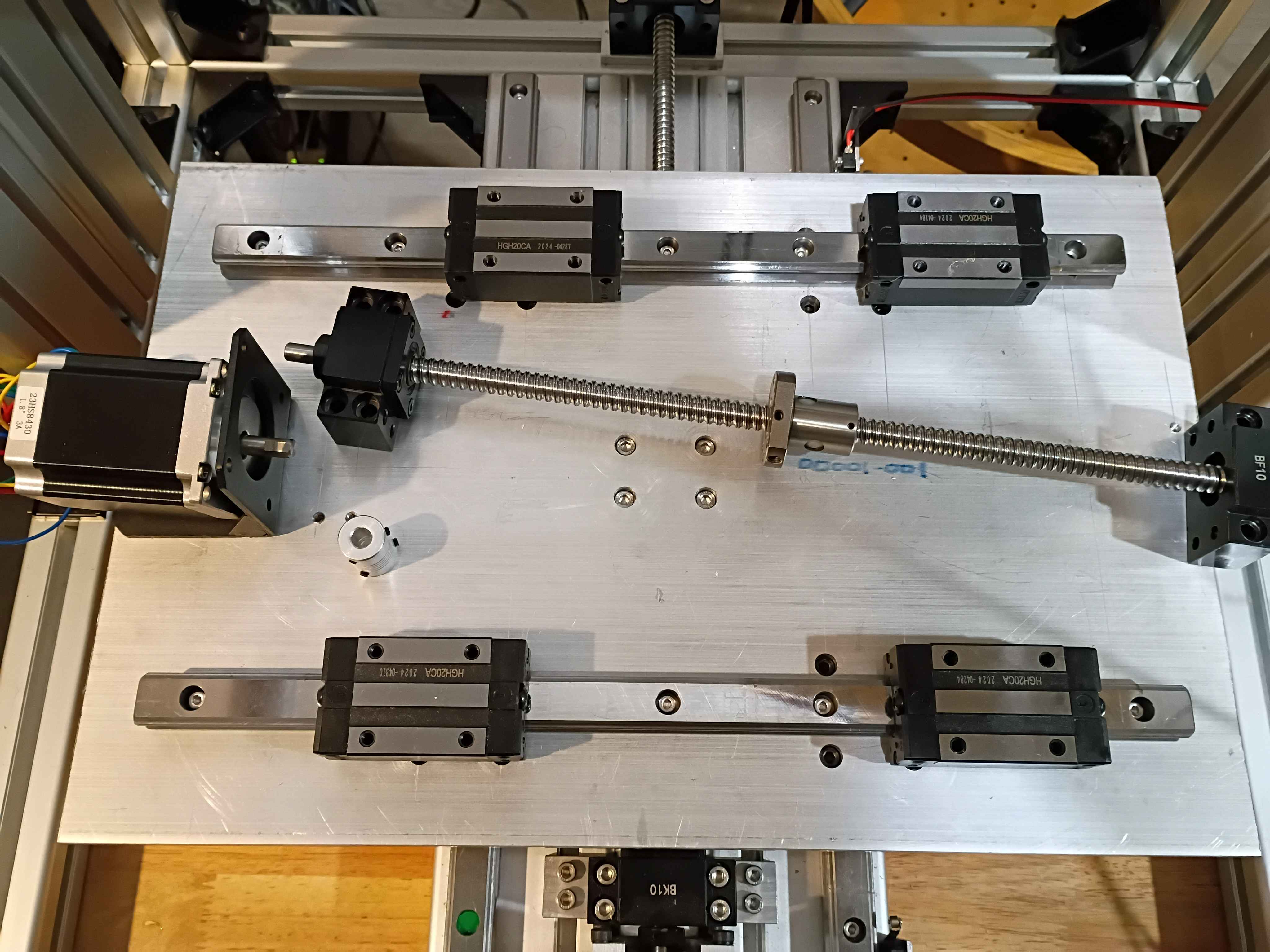
Set up automatic redirect from https://www.marian-scientific.org/22001 to the corresponding folder of the GitHub project repository. Also updated the code and documentation to match.
Completed fabrication of serial number 002 and shipped to our sister facility for future product development. See video of it working during QC testing. it does look pretty snazzy. 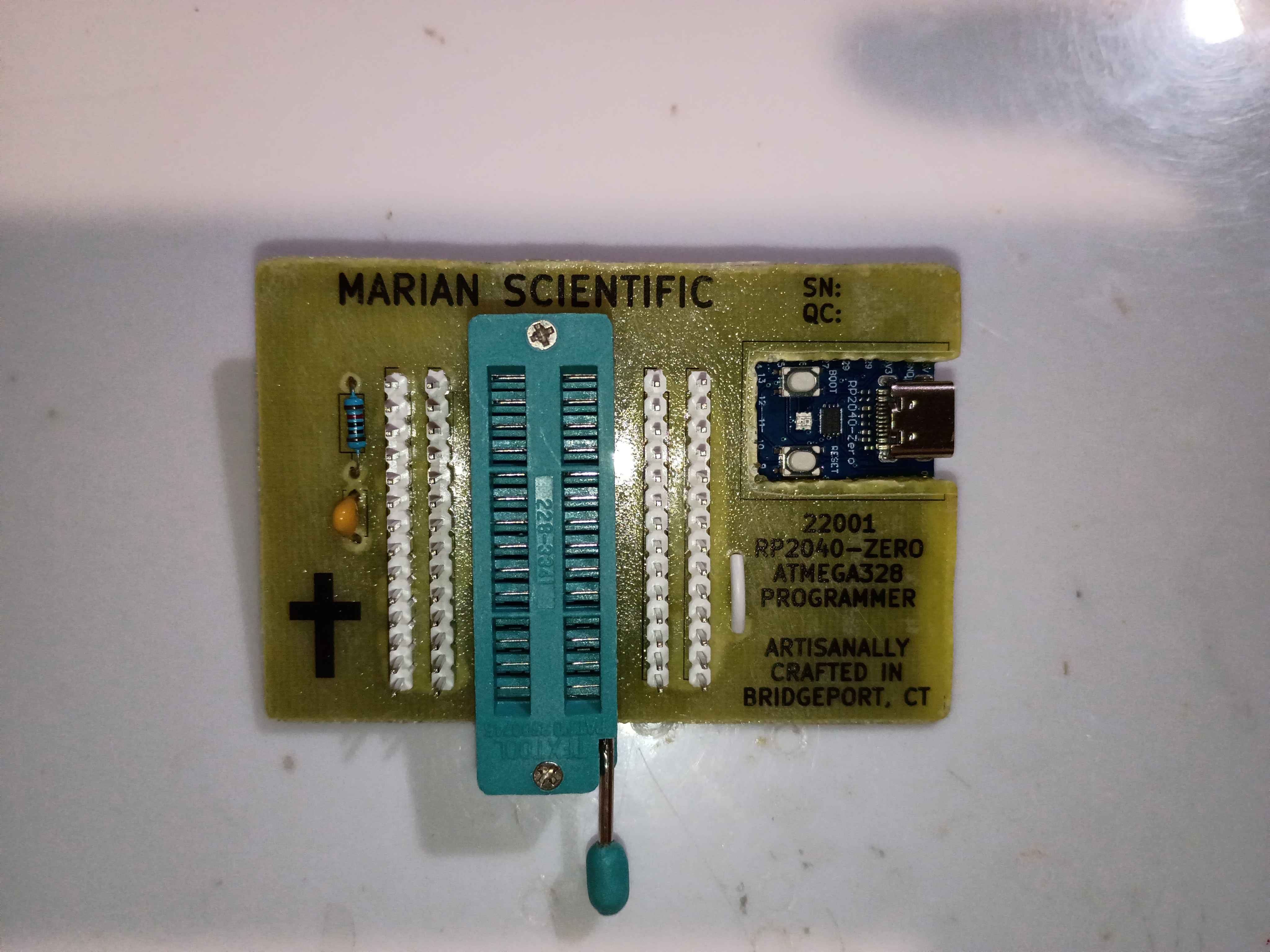
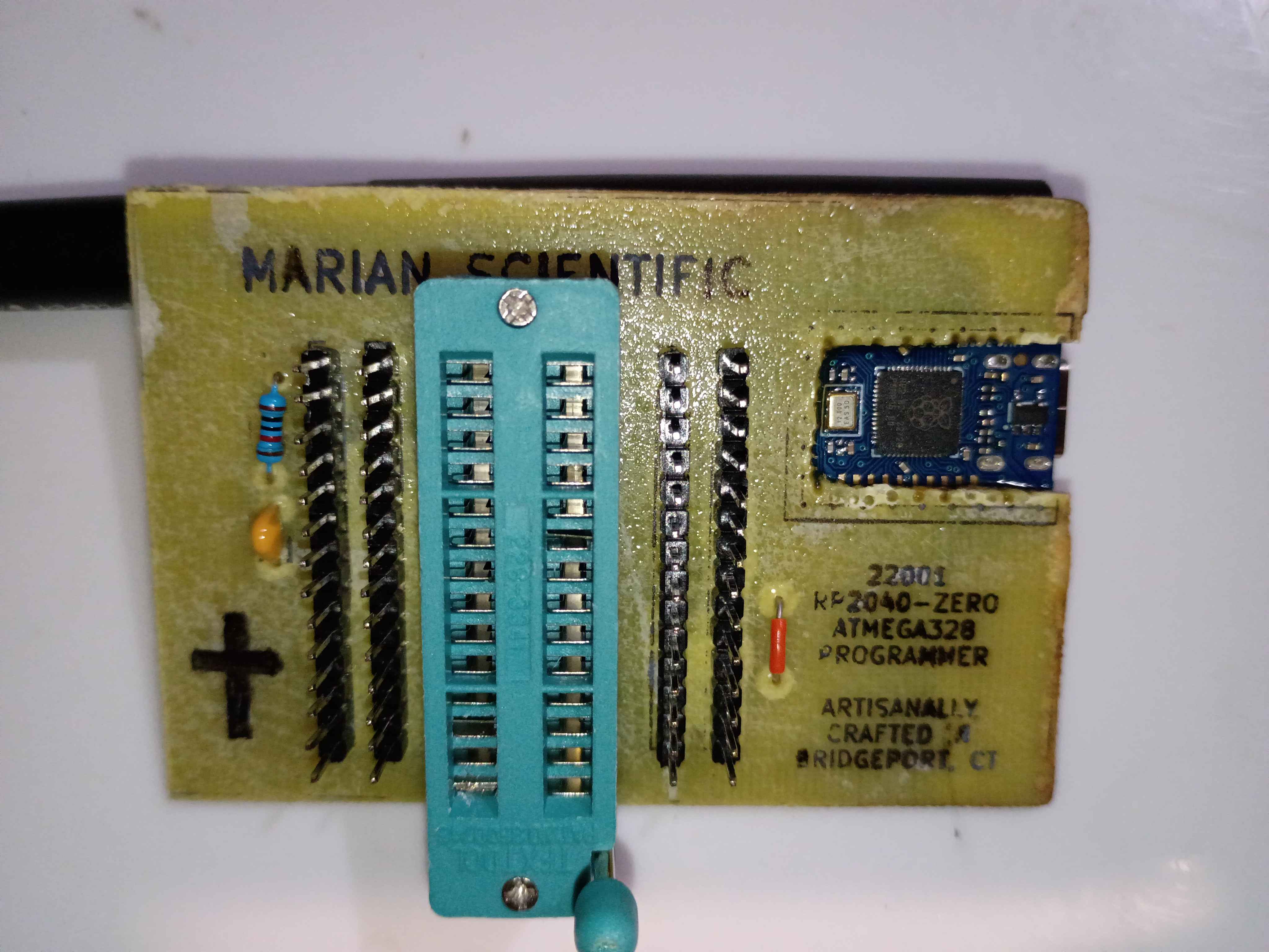
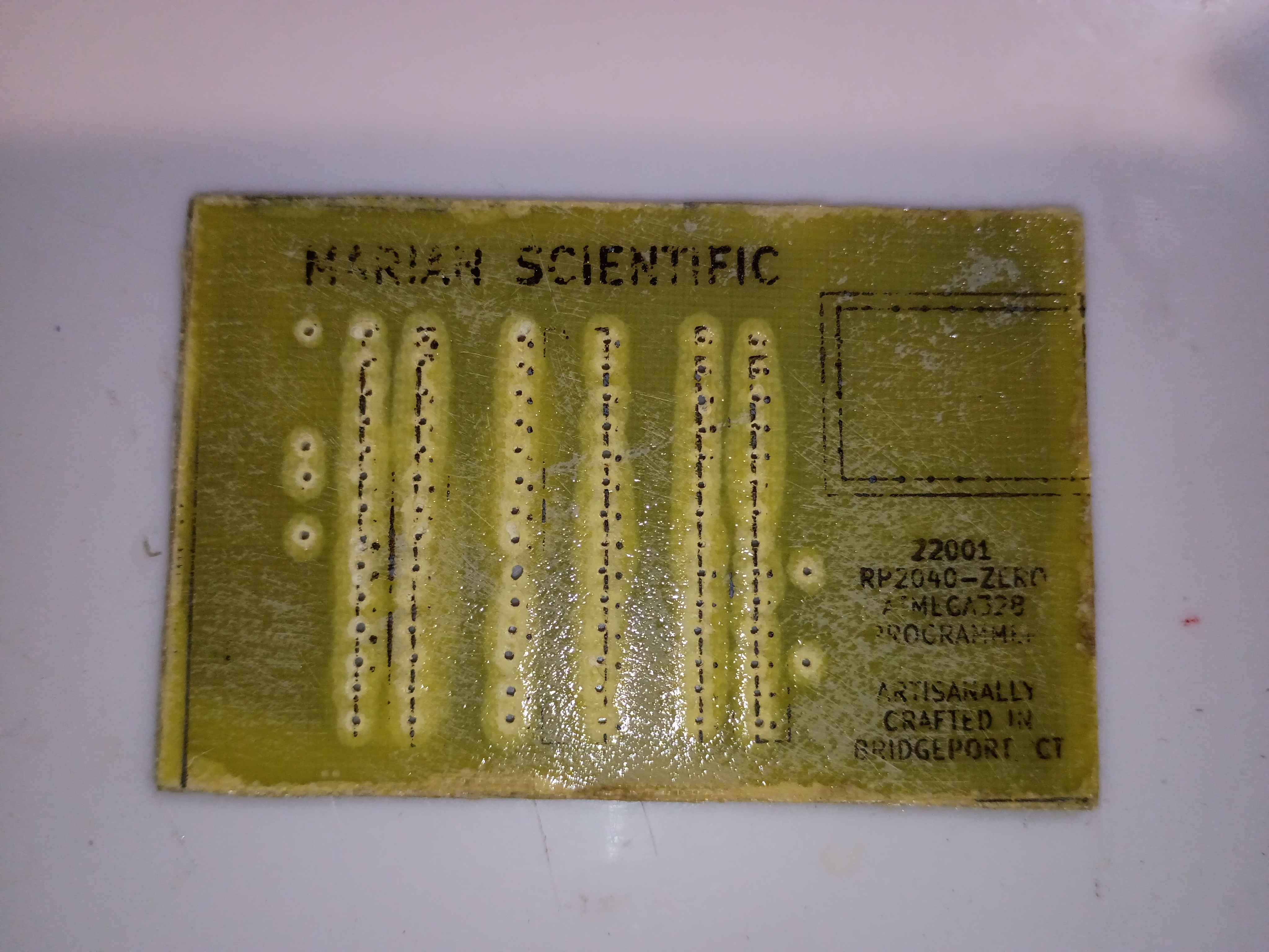
Attempting to make an improved version to provide for internal R&D efforts. Updated the PCB design to improve the text spacing on the F.Silkscreen and add a spot for serialization. Etched another PCB and drilled thru holes, slightly nicer than the previous one in a few different ways. Attempted in vain to toner transfer the silkscreen onto the front face for the final time. Decided to just use a sticker for the foreseeable future, as it's not worth the effort for toner, and it's less robust anyway. Just waiting on some ZIF sockets before I can assemble. 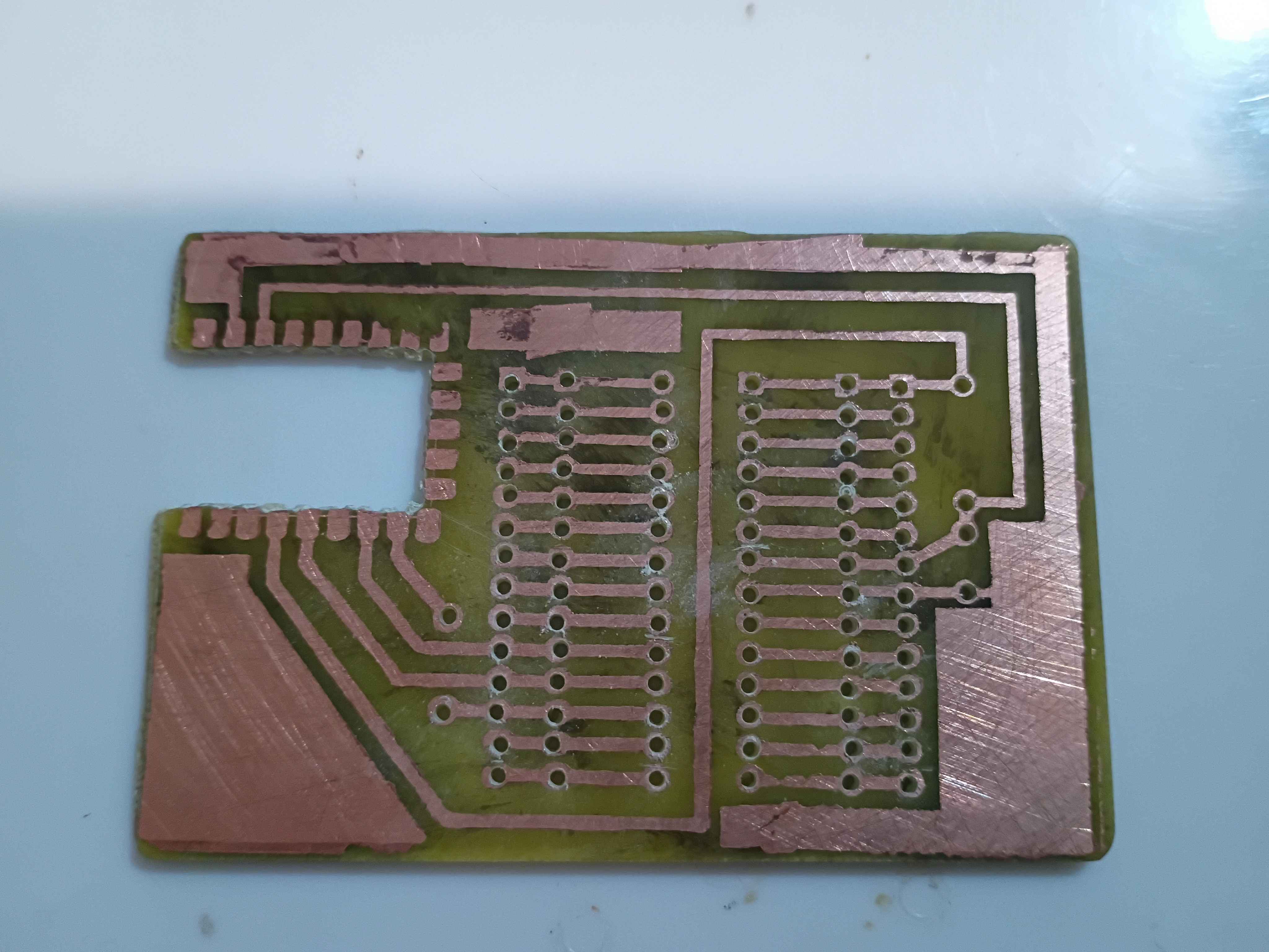
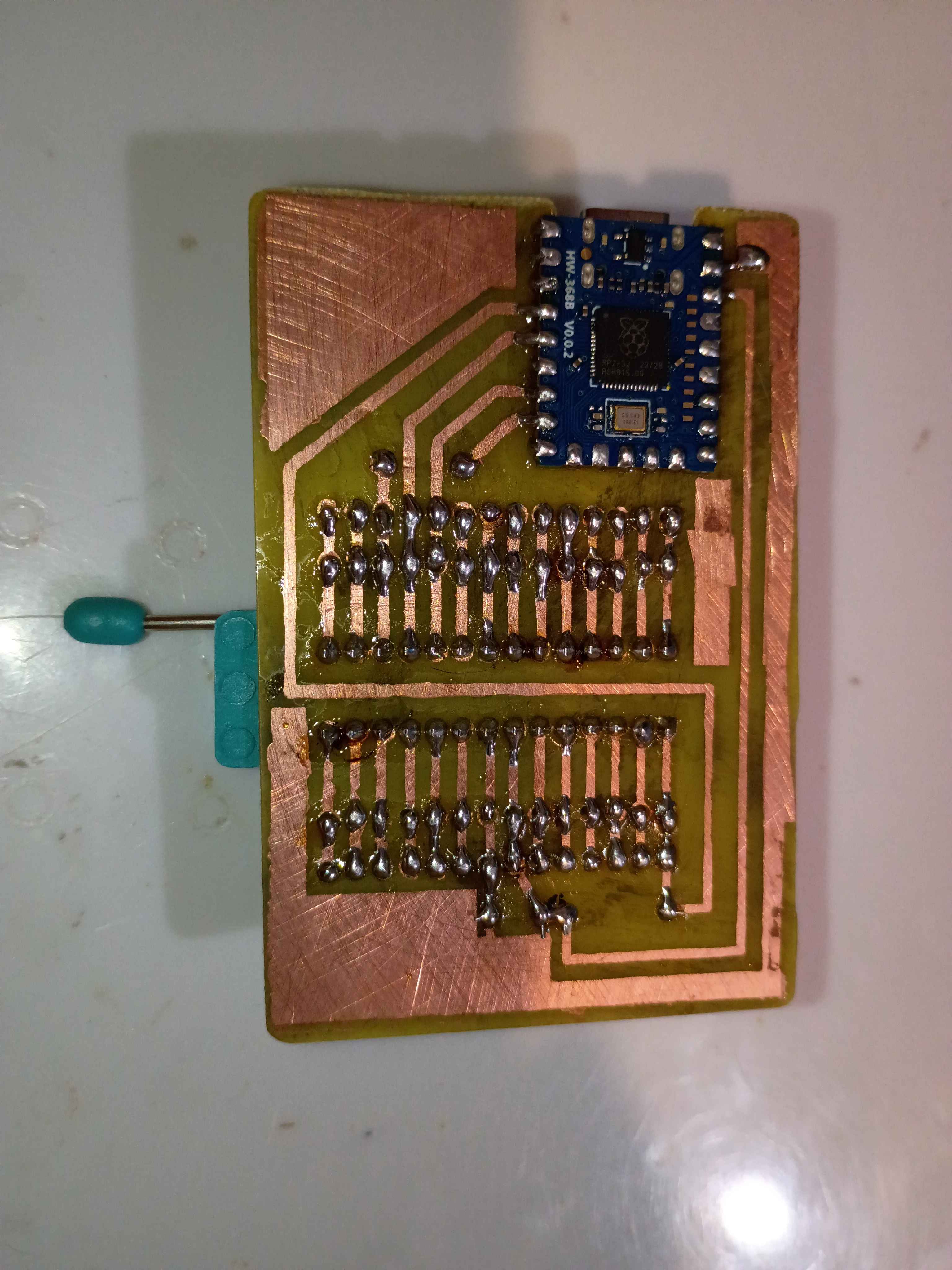
I re-soldered the RP2040-Zero board right-side-up, but the programmer still wasn't working. After a shameful 2 hours of debugging, I finally realized I must have fried some magic pixie gems inside the RP2040 by soldering it and running it the wrong way around, so I popped a new one in and it worked a treat. Project complete! See video of it working. If I make another one of these, I will try to do the toner transfer better. It might even warrant an investigation into the heat and pressure levels that give the best results. 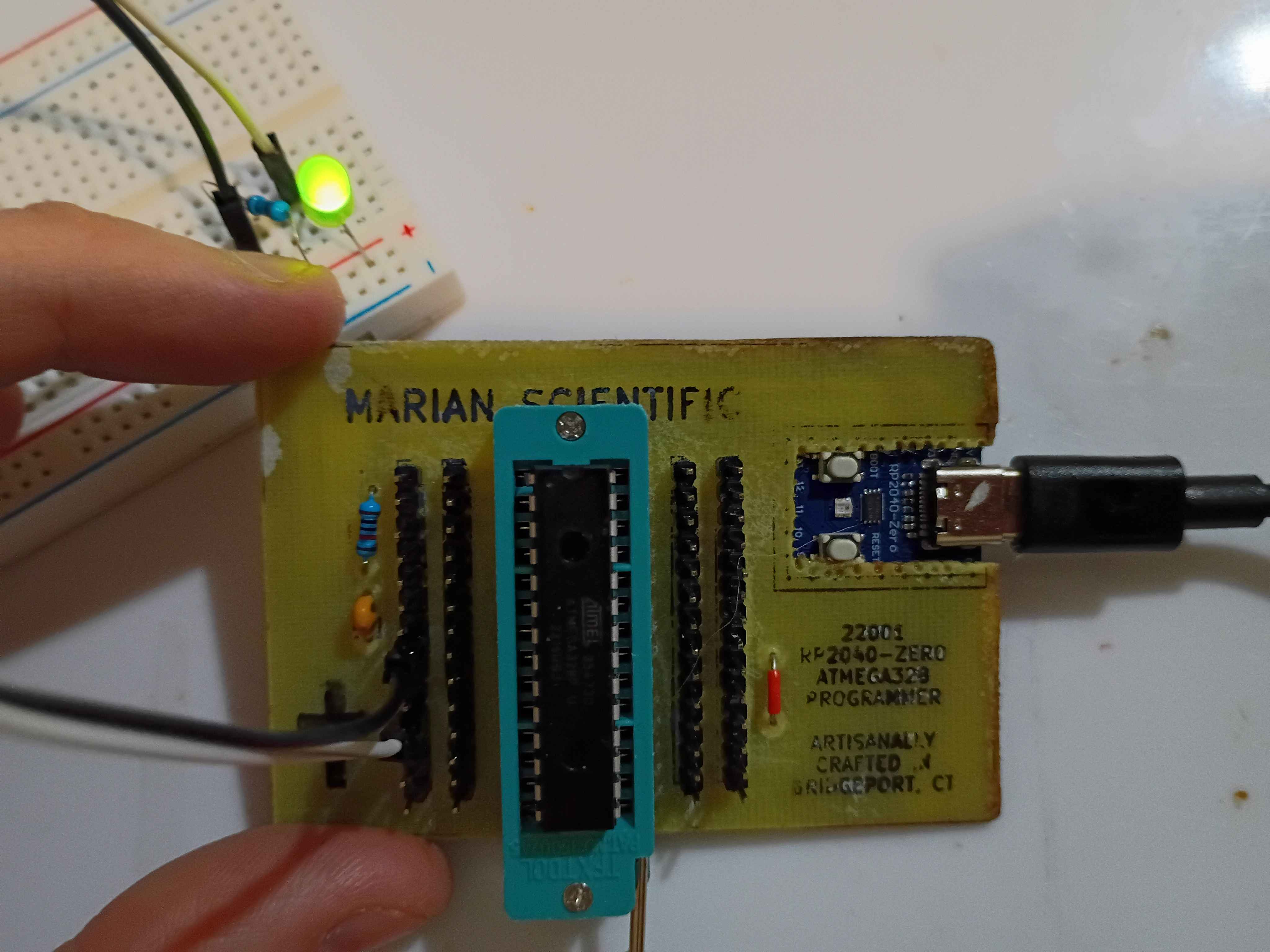
I redid the toner transfer of the B.Cu mask. For the areas that didn't transfer properly, I put some blue masking tape, 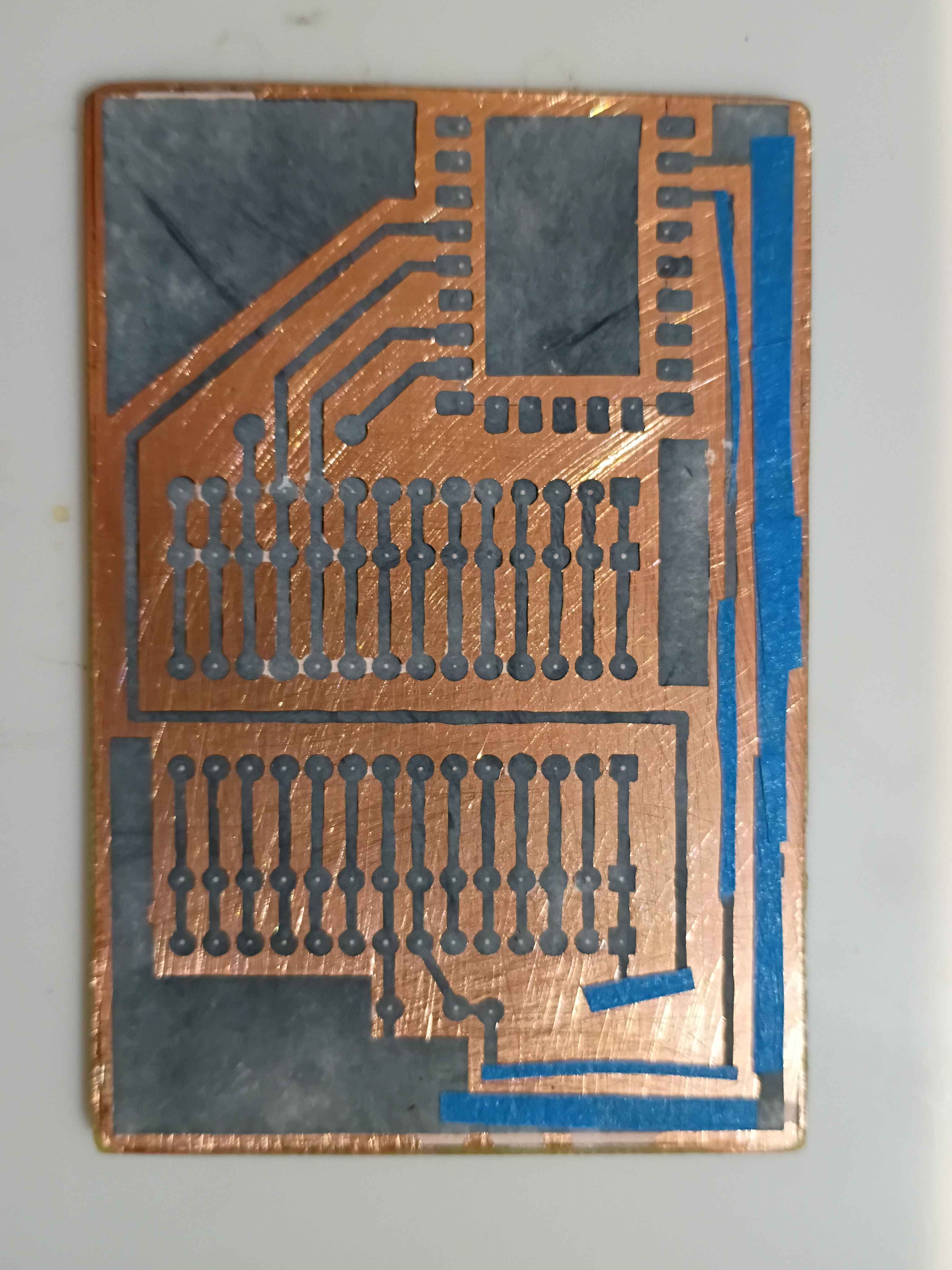
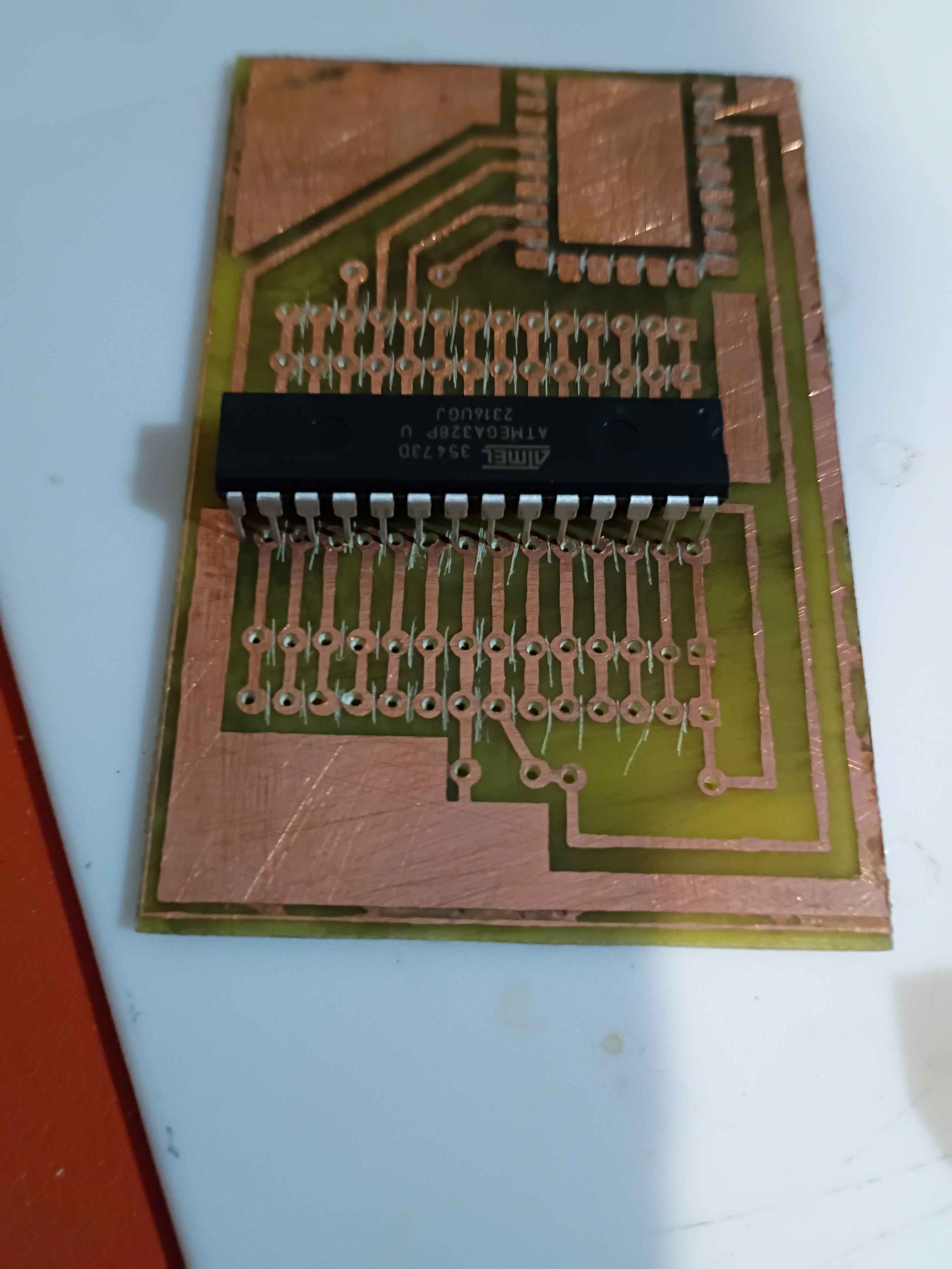
and that worked surprisingly well. I drilled out all the holes and even cut away the rectangle for the RP2040-Zero board. 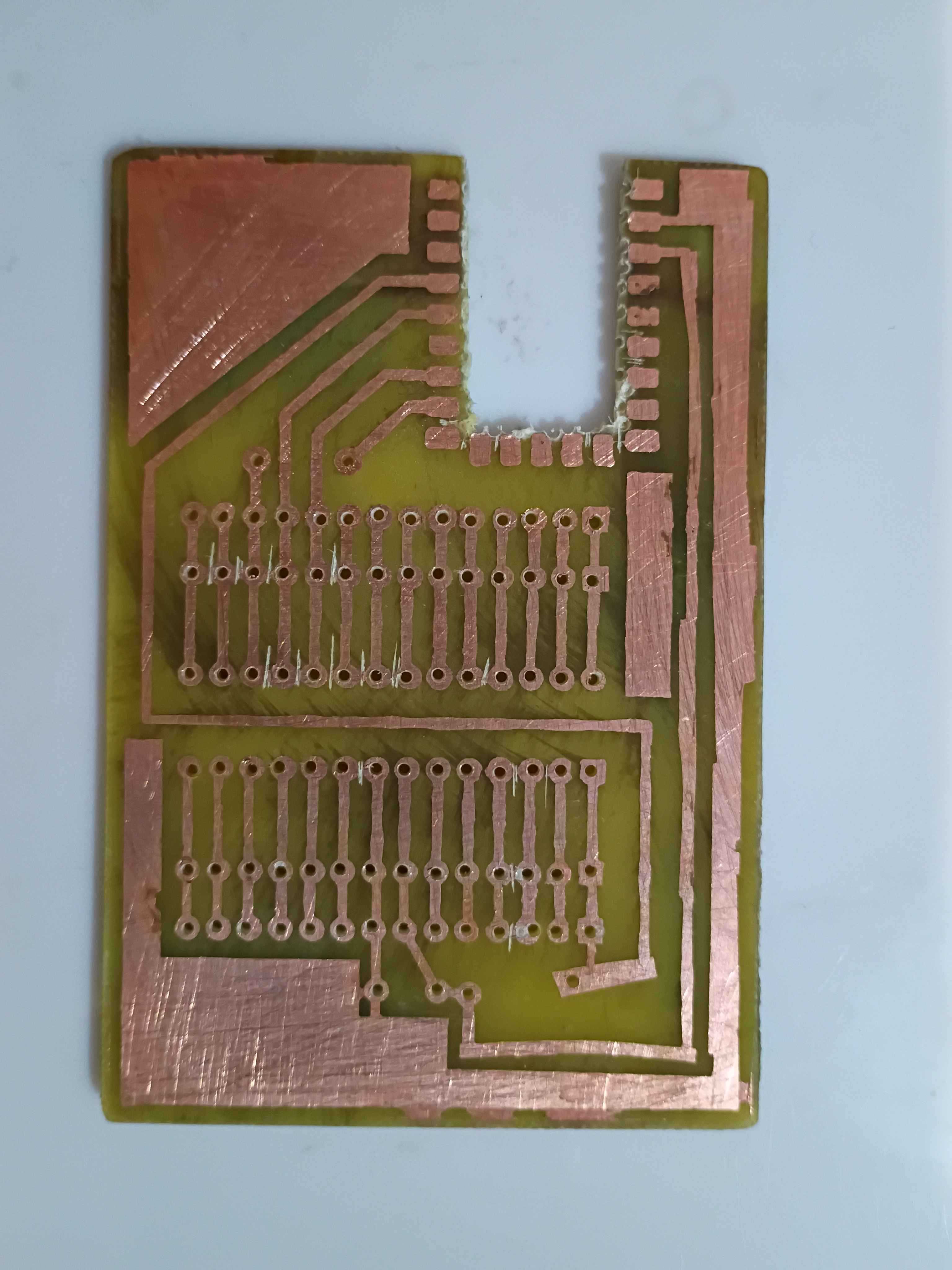
The toner transfer for the F.Silkscreen was not so successful even after a couple of attempts. I think it's because I sanded the fiberglass. I just retraced the parts that didn't transfer with black marker. 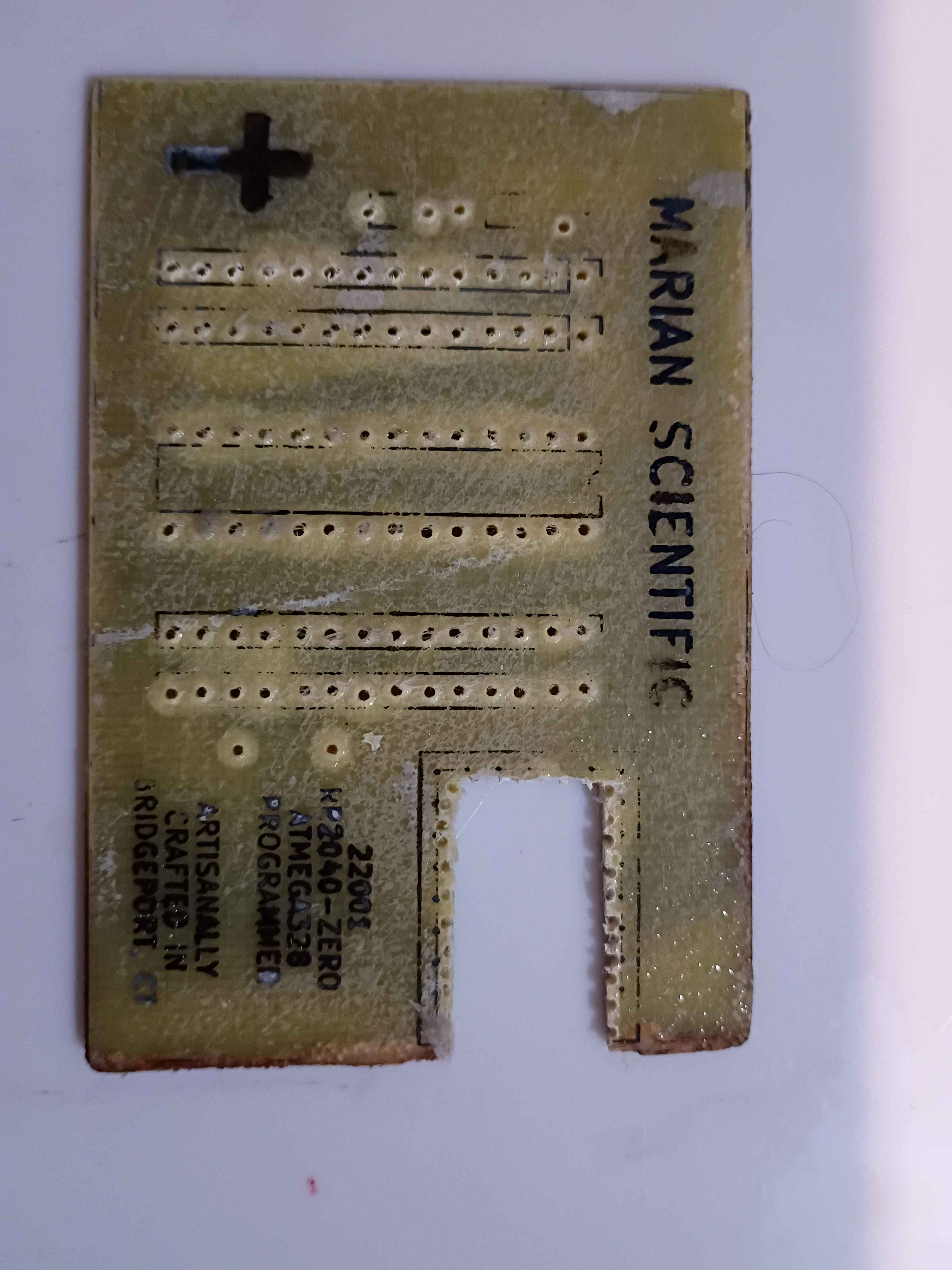
I soldered the components to the board, and it all looks great, until you realize I soldered the RP2040 board inside-out... I need to fix that tomorrow. 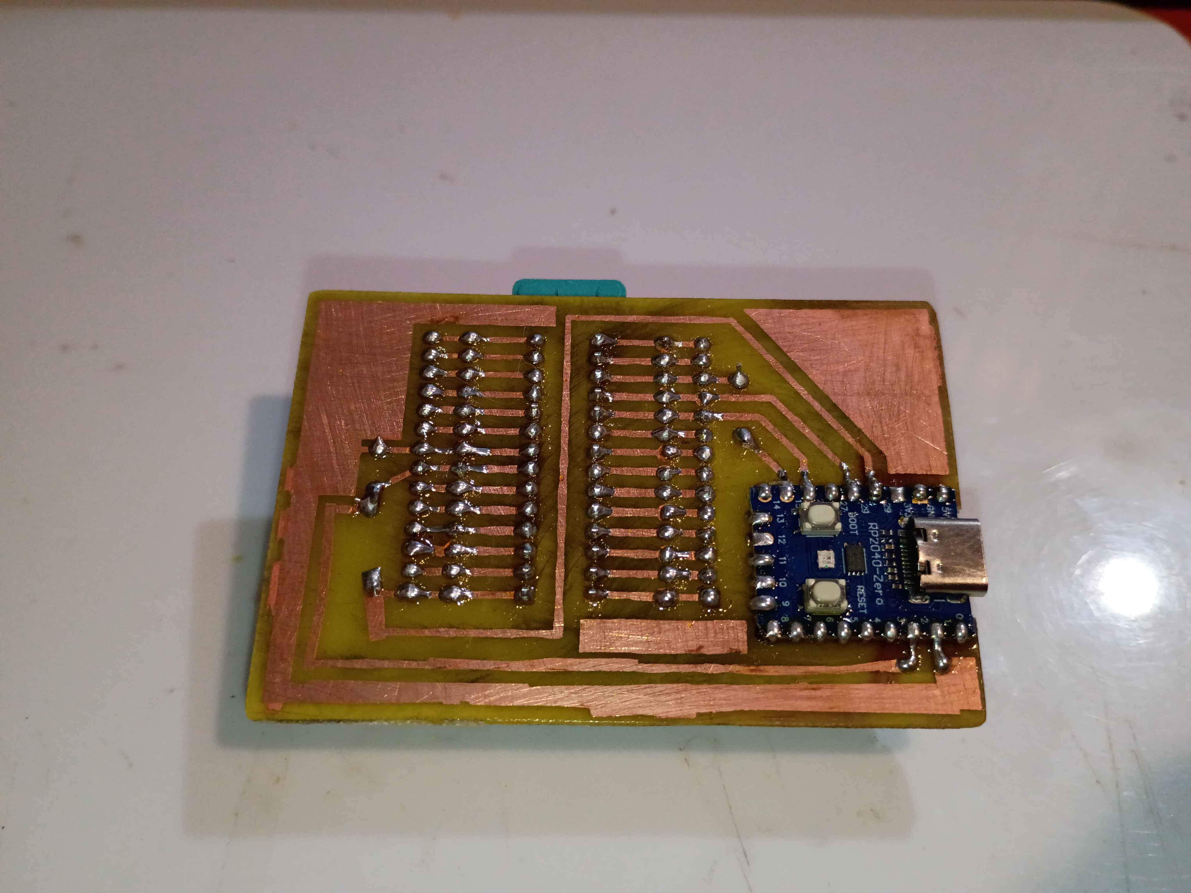
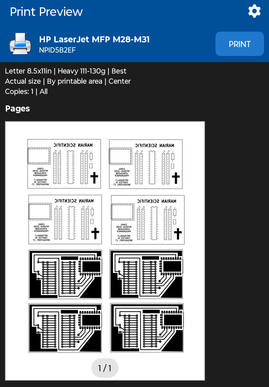
Sigh, apparently printing the PCB mask PDFs from my phone was a bad idea, since it automatically resized them down a few percent to "Fit to Page", and now none of the components fit, rendering a few hours of work yesterday and today completely wasted, except of course the practice etching and the lesson learned.
I reprinted the PDF with "Actual Size" scaling using the NokoPrint app and the settings below.
Before I realized I had the sizing wrong, I did retry the toner transfer of the front silkscreen, and it mostly worked, although the cross and some of the letters did not come thru. The areas of toner that didn't transfer properly, I filled in with marker. I can try again with the correct sizing tomorrow, which should help, although the cross probably didn't have enough direct heat applied to it to transfer.
Used Inkscape to put a bunch of the background copper and silkscreen masks onto a single sheet and printed that on glossy paper. 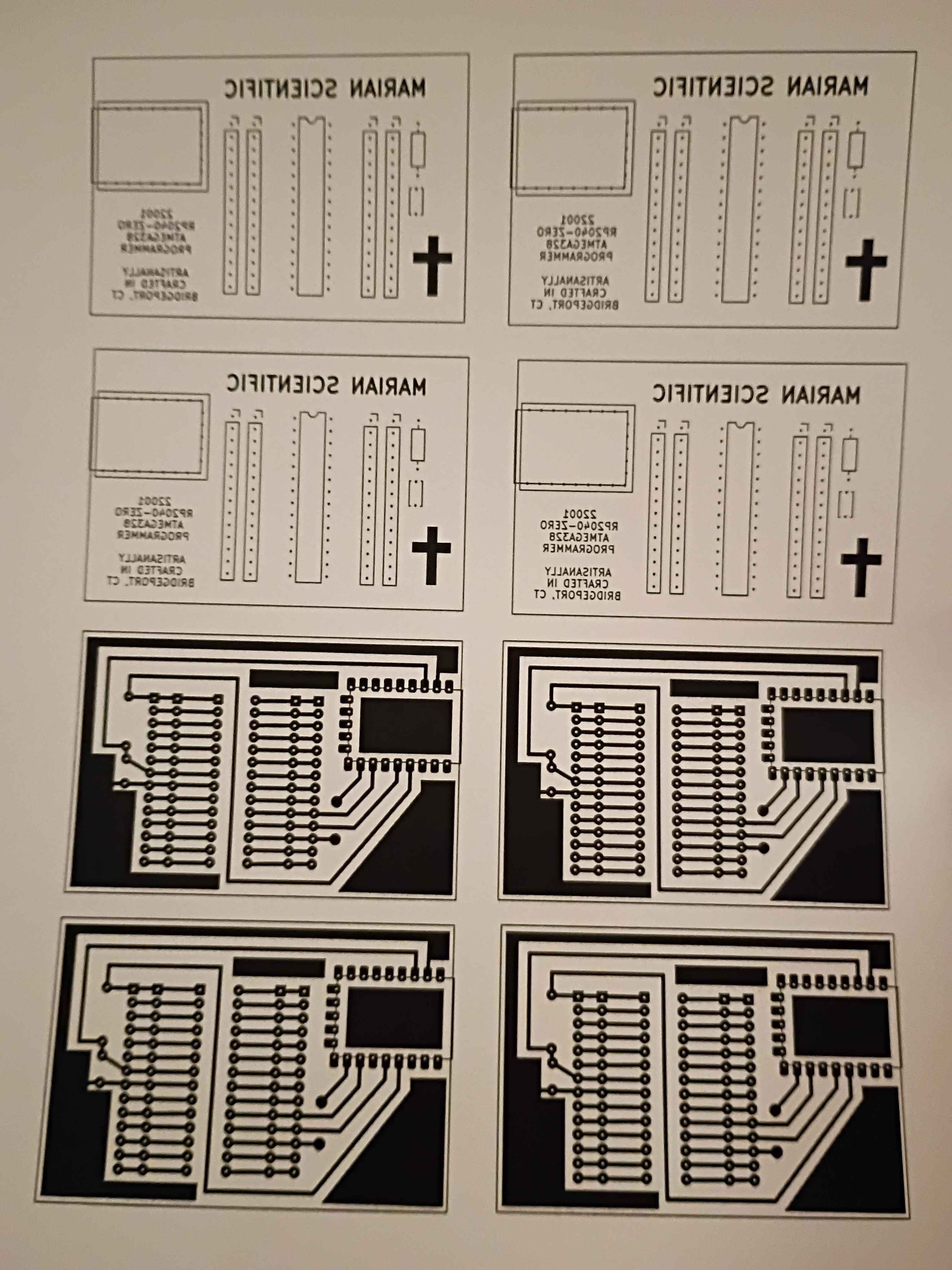
Hopefully successfully implemented a minimum set of functions for Mary-Bot. This post is the first test of the live software.
Continued development of Mary-bot. Got the Python bot to more or less successfully run the bash script that regenerates the entire website, though the paths need to be updated for the links and the image references. Still not yet ready for full journal submission migration.
Continued development of Mary-Bot. It now can automatically name images entries. All the user needs to do is type [IMG] in the corresponding place in their text content. Not yet ready for full journal submission migration. I'd like to put in the ability to edit entries thru Discord commands as well.
Continued development of Mary-Bot. She can now track and edit the project list thru Discord commands and populate a new journal .ini automatically along with uploading a set of image files. Another day of work will be required.
Set up VPS with https and attached it to the marian-scientific.org domain. Set up the preliminaries of Mary-Bot, a Discord bot that will automatically push journal entries to the site. Another day or so of work will be required.
Updated draft schematic and created PCB design for the main control board using the latest PCB-etching lessons learned. This board will be fabricated in-house. See 03010-002 Kicad project. 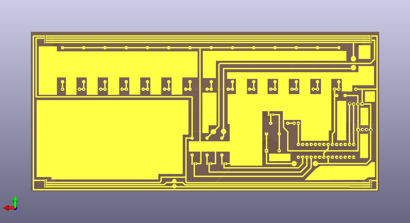
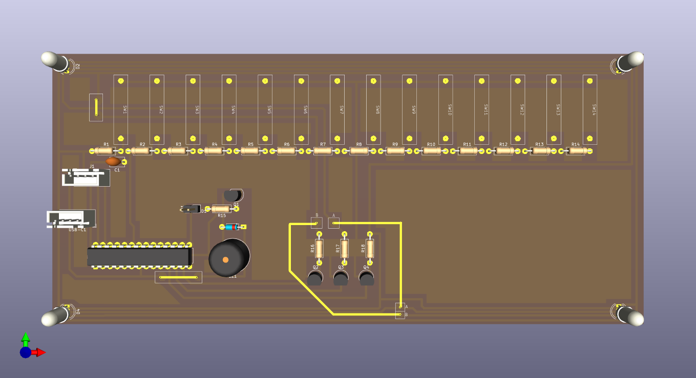
Created draft schematic for the main control board. See 03010-002 Kicad project. 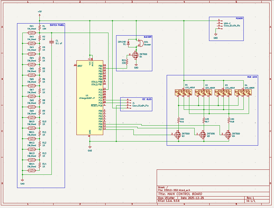
Created SVG for laser cutting & engraving simplified ruler. See project CAD directory. 
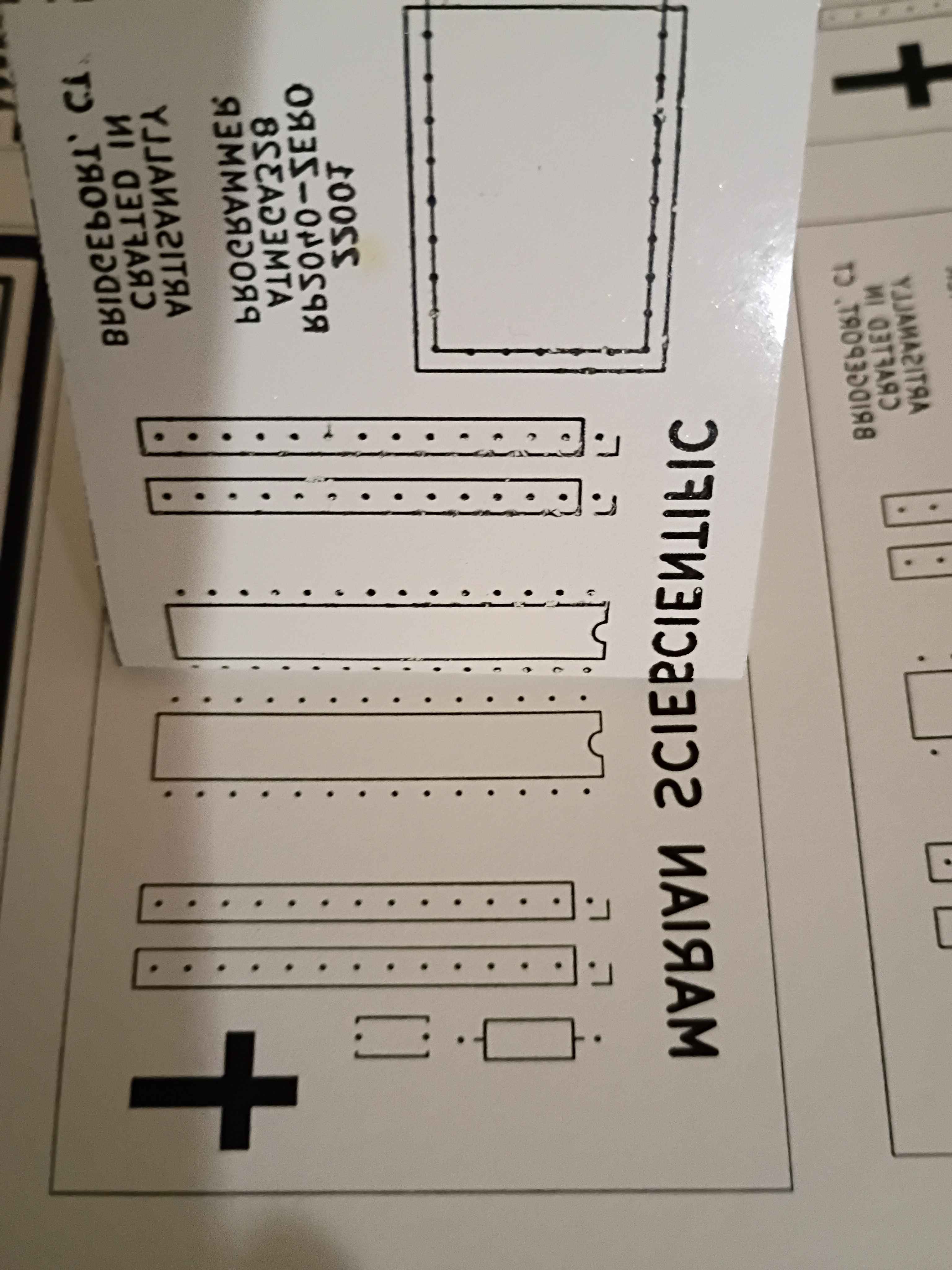
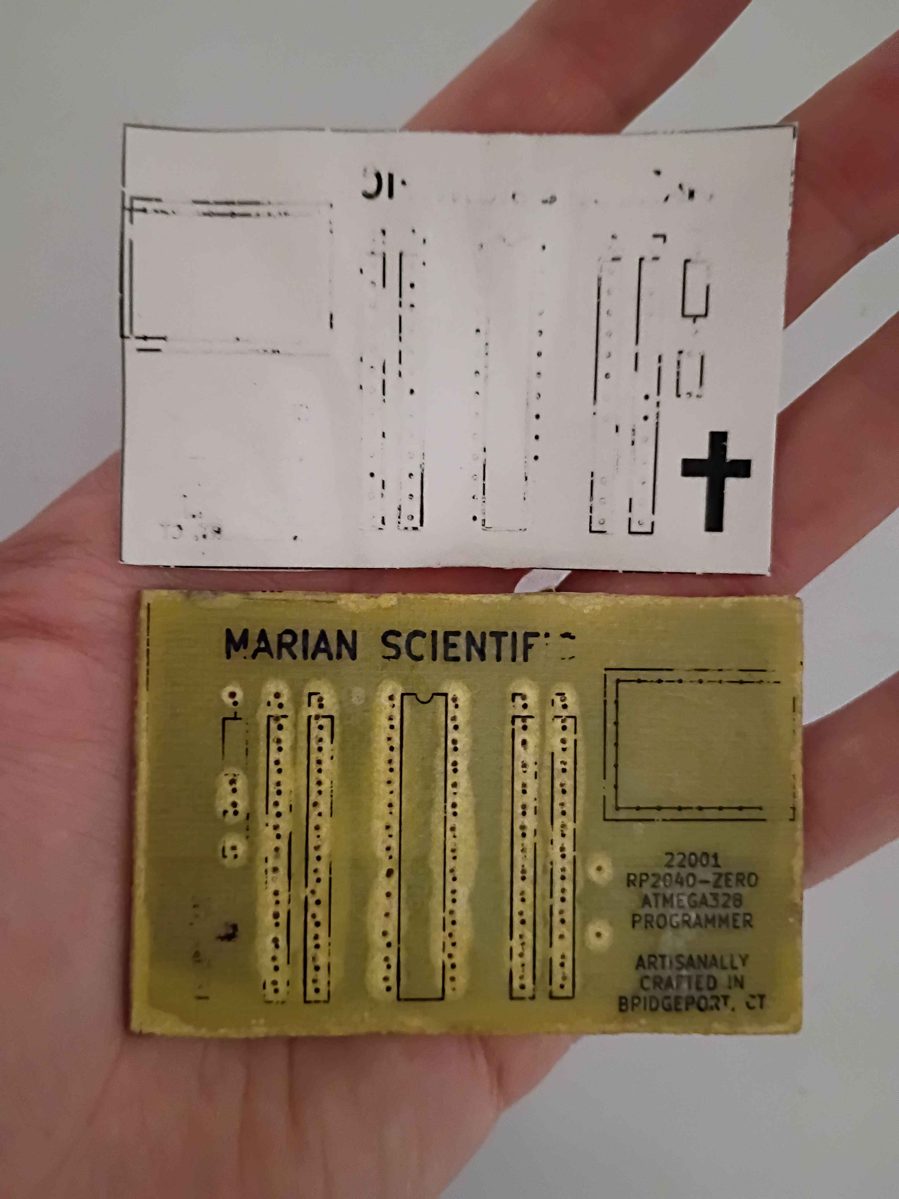
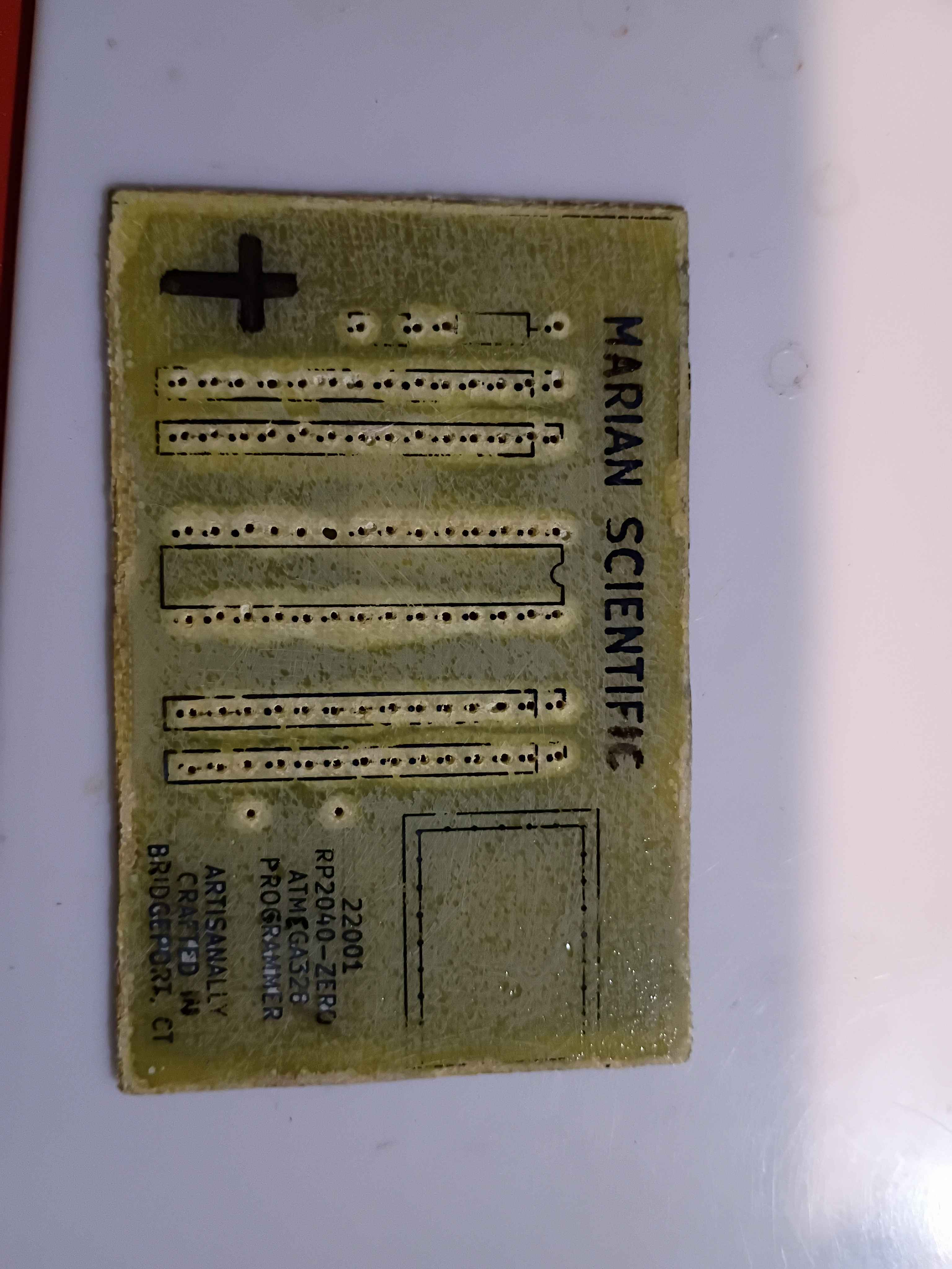
Incorporated a host of improvements to the PCB design of the 12001 RP2040 AVR programmer into a productionized version. See project entry for a list of the improvements and the CAD files. I can begin to fabricate some of these when I get back from my trip.
After brainstorming follow-on math manipulatives with the client, we are launching a prototype effort for a manipulative involving ruler measurements. As was learned on xMM1, moving parts and a tactile input device make the manipulative very engaging for the children. This manipulative will consist of a box with an exposed sliding piece of plastic that the children will need to measure. The plastic slide will be connected to a rack and pinion so it can be driven by a servo to expose different lengths of plastic to be measured. The children will need to place a ruler against the box, and to make sure they line up the ruler correctly with the start of the plastic slide, there will be a reed switch that detects that and shows a green status LED. When the measurement is made, the child will be able to select the value (in half-inch increments) using a pegboard, by putting a peg with a magnet into the corresponding marked circular slot. The different values can be connected to a series of resistors to be able to detect the voltage value with a single ADC pin, versus having to waste a lot of GPIO pins. If the rack and pinion approach does not work due to space limitations, a servo-controlled paper scroll can be used instead.
Designed programmer PCB and attempted to create a DIY PCB at home using etching solution. See video of it in action. The photos below show the final product which actually works well as an Atmega328P programmer; I tested several blink programs. The rows of header pins also almost make this into an Arduino-like devboard, though it lacks any external oscillator or other peripherals. I did have to shave down the bottom of my USB-C cable so it could come in flush. A lot about this whole project could be improved significantly, but I had a lot of fun with it. This investigation was a massive success, and we did barely manage to complete it on schedule
Got the programmer working, which was a combination of the code running on the RP2040 and a Python script transmitting the serial data over USB from my PC. See video.
Wasted ~2 hours today alone tracking down a very dumb mistake - I was off by one on the SPI pins on the Atmega328. No wonder I wasn't getting a response. I completely obliterated the code trying to track it down, so I will reconstitute something clean tomorrow. The AVR chip nonetheless acknowledges our attempts to program it now. 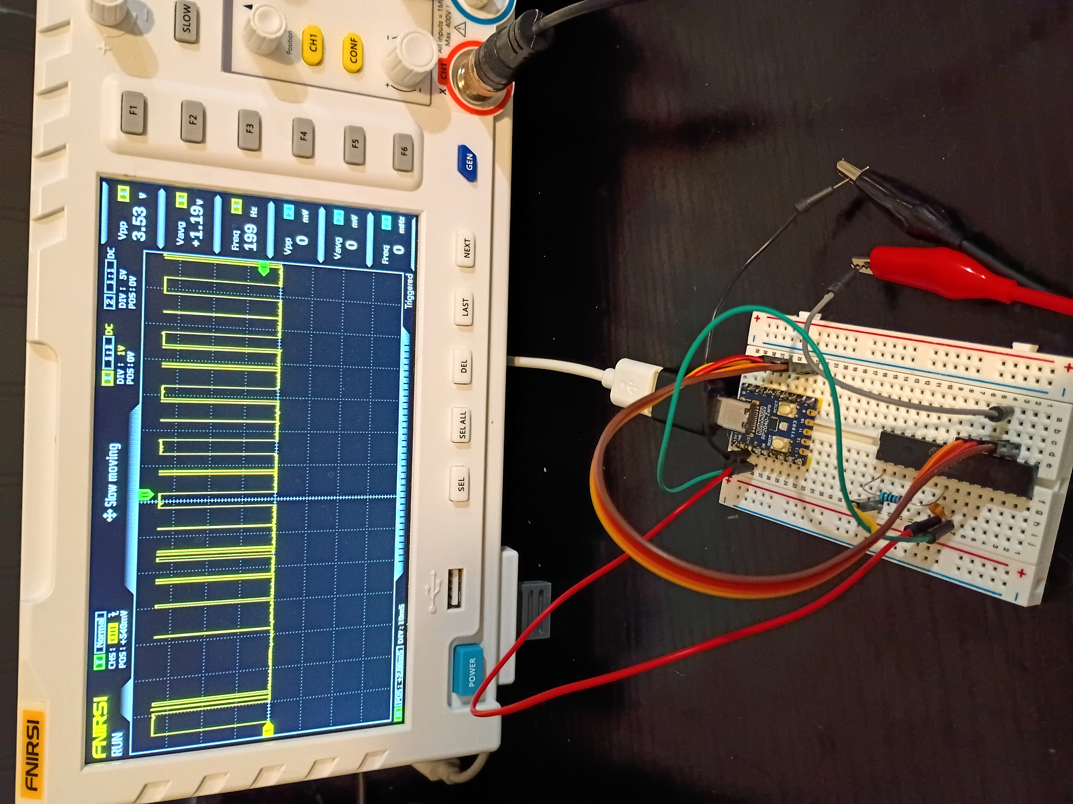
Finished a likely buggy implementation of both the rp2040-USB-programmer and the PC-based hex file transmitter using python. See code directories 005 and 006. The clock and data transmission works as expected, but for some reason the Atmega328P is completely unresponsive; no signal is being transmitted back over MISO. 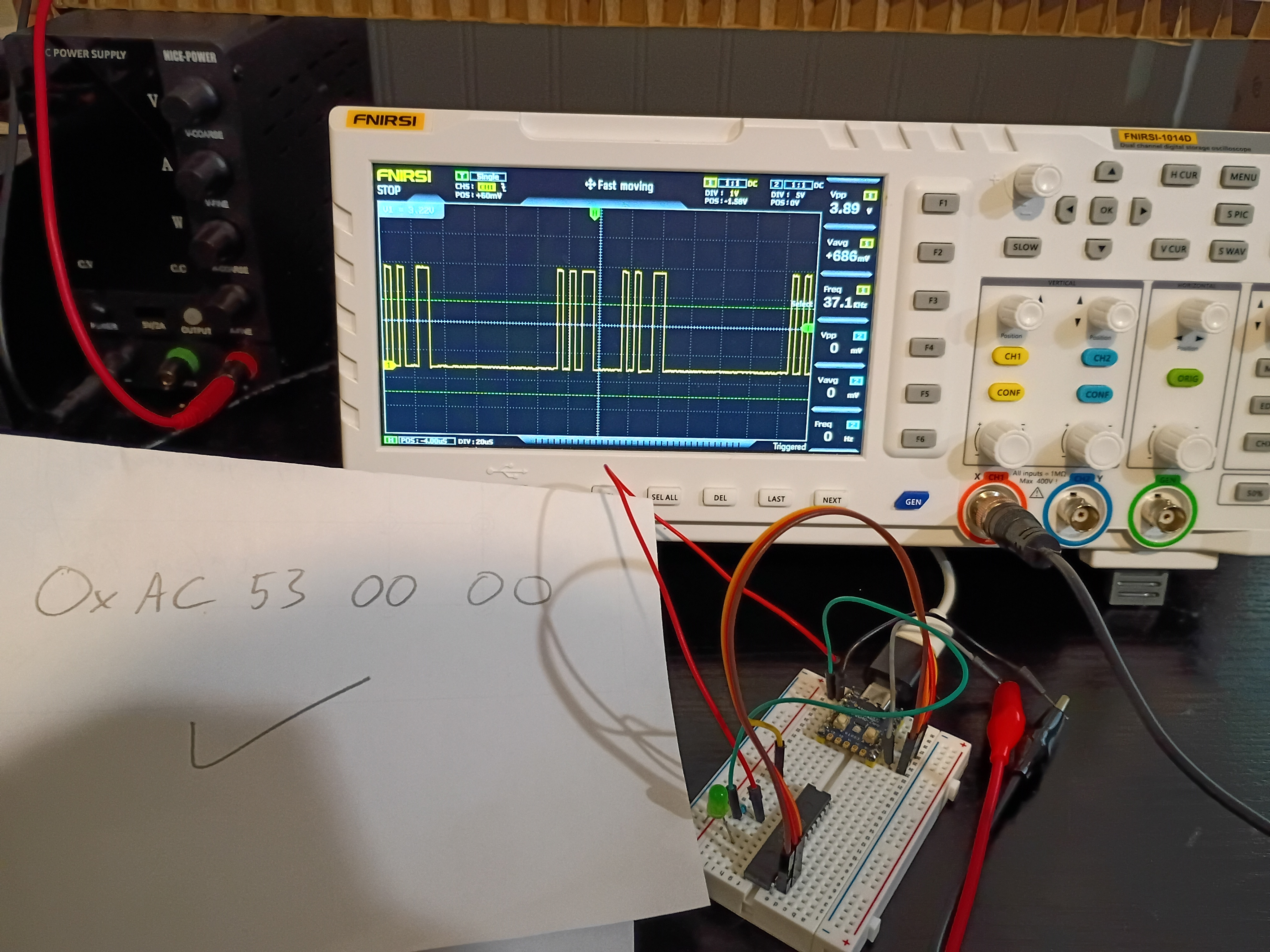
Soldered pins to the RP2040-Zero board for preliminary breadboard tests. Got control of the built-in RGB LED working over PIO (very interesting and powerful) and began working the ICSP algorithm. Link to top-level project directory.
Launched short-term investigation into developing a RP2040-based programmer for AVR ICSP-capable chips, especially the Atmega328P. After internal discussions 2025-12-14, both of these chips seem to be the best avenues for future electronic project development. Completed first three preliminary tasks establishing a functional Atmega328P and RP2040-zero toolchain to complete the remainder of the investigation.
Received 6 of 6 (no extras) 03007-001 stepper coil-driver PCBs from OSH Park. They arrived in 15 days. The communication from the company was far better than DKRed. The board quality is decent, and the price is comparable. Boards (purple cheapest and default option) do come with jagged edges where they are broken from a larger PCB platter. I do prefer them to DKRed. 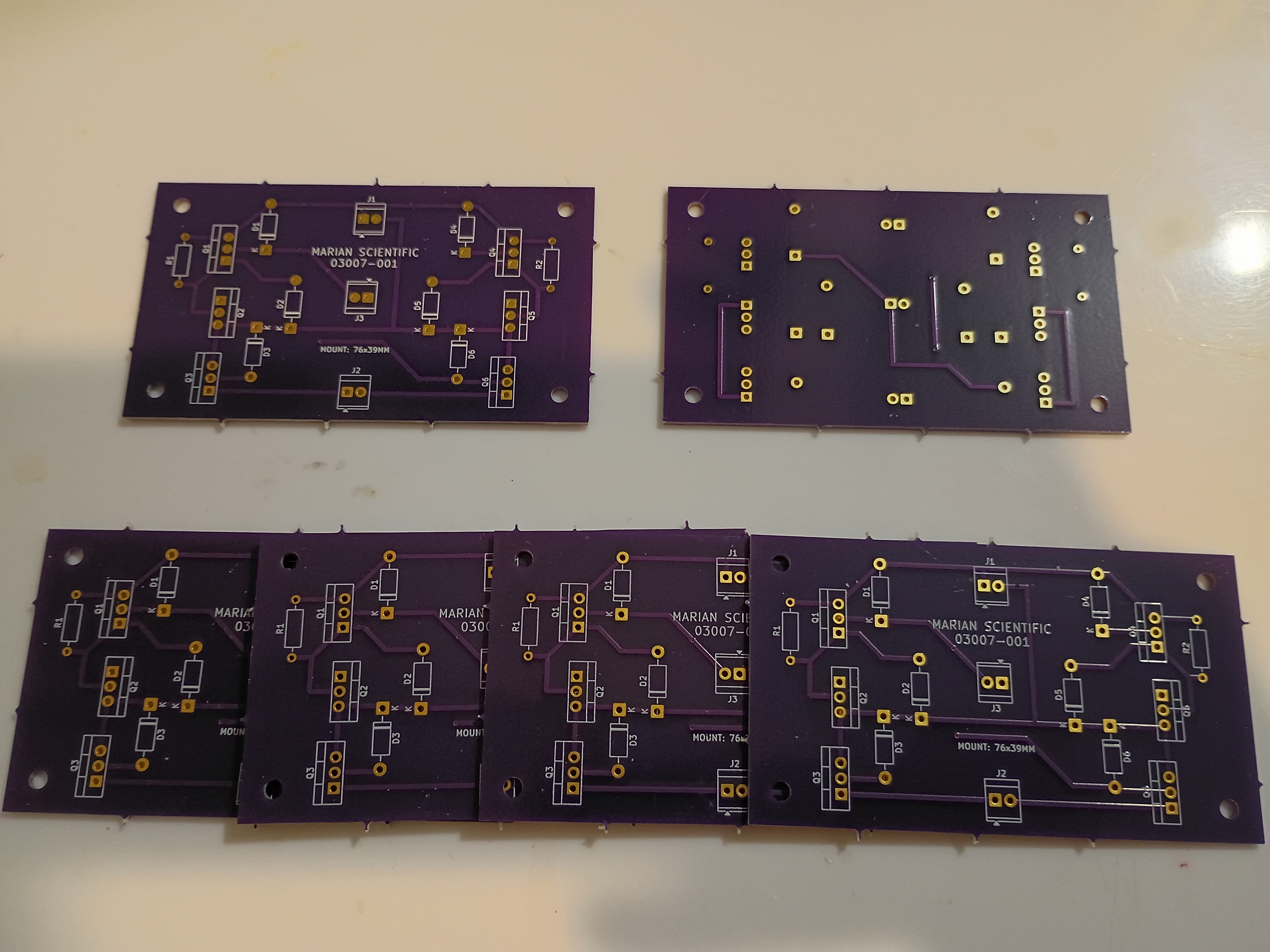
Recorded final video of manipulative working. The prototype will be used as a template for a future productionization effort and, afterwards, permanently donated to the test classroom.
Tested the project with 6-7 year olds, and it was a massive hit. Kids were fighting over the 3 magnetic input blocks, and I kept a half-dozen or so busy for around 15 minutes during dismissal. They thought it was professionally-made. I think one factor about the manipulative that they enjoyed was the tactile nature, which is not something familiar to them in an age of touchscreen-everything. 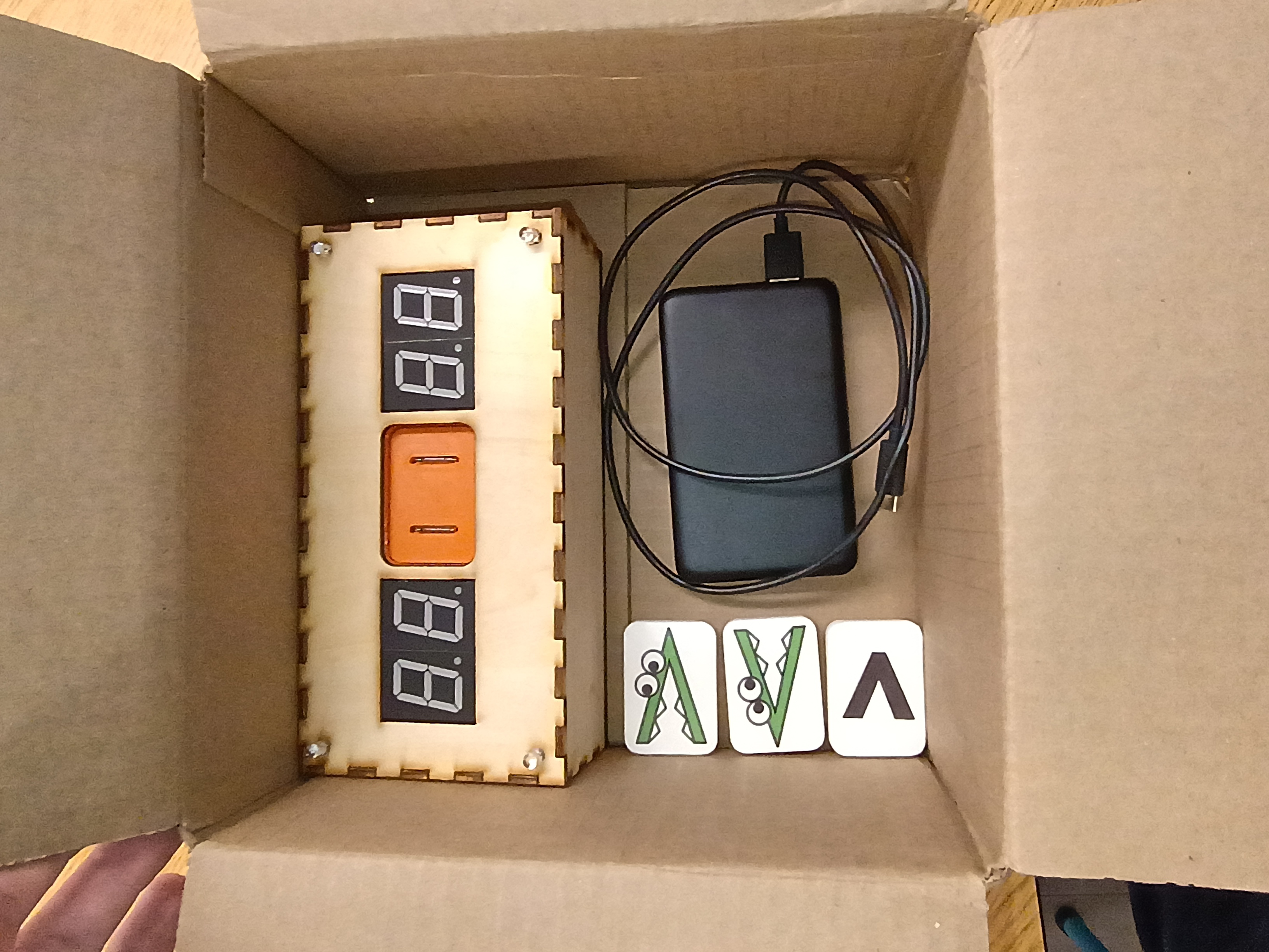
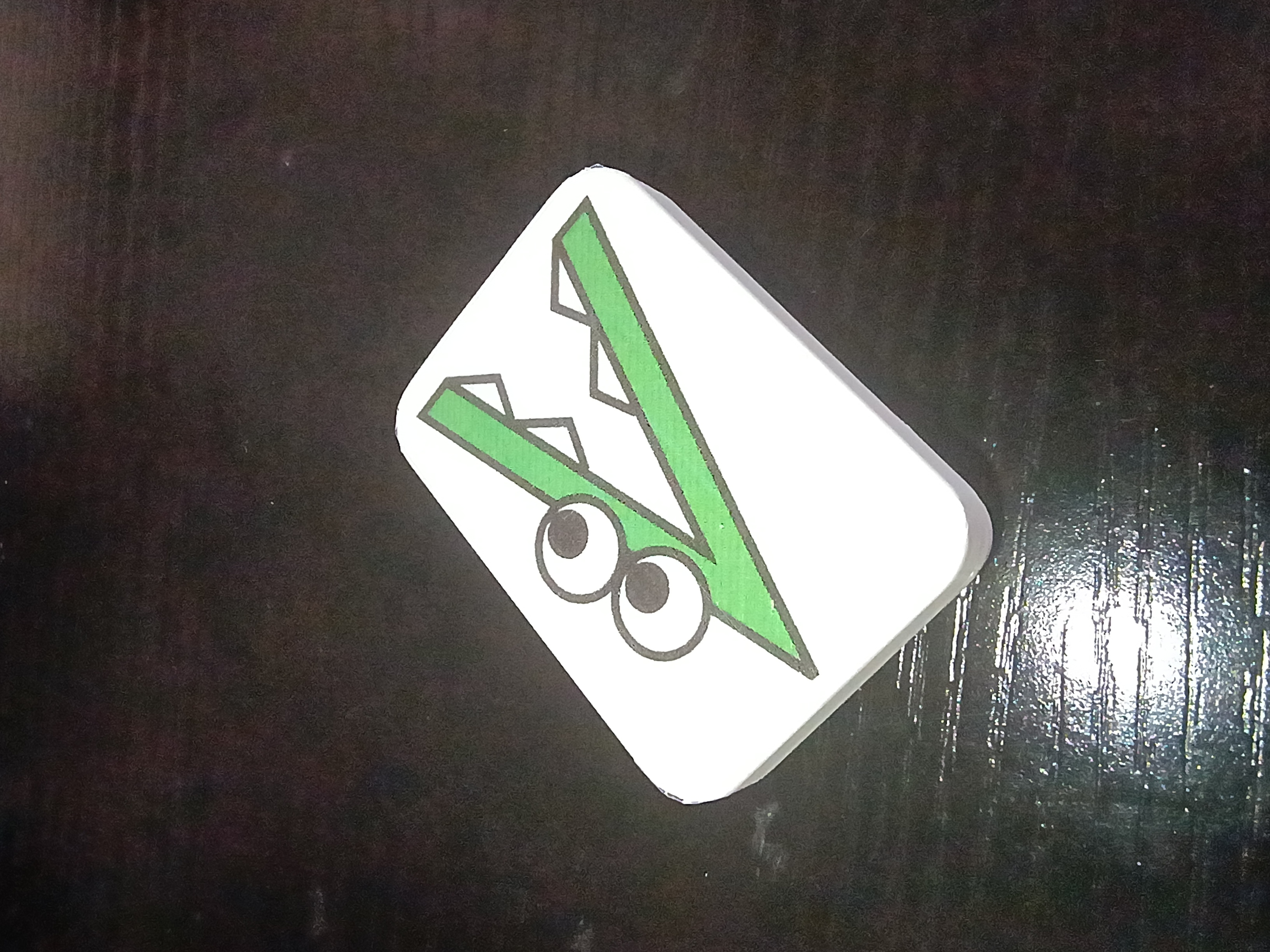
Project complete 3 days early. Made final updates to the full project code to fix the RNG and the intermittent failed 7-segment initialization. Also somehow the power draw is now high enough that it doesn't seem to automatically shut off the USB power bank, though the power bank still reads 100% after 3 days of testing. Designed a new 03008-010 input block with standoffs and a bigger grip area. See latest CAD. Printed two versions in new white PLA and applied the 'Alligreater' image (one mirrored) to the front with a glossy transparent parent sticker. Will test this device with the children tomorrow. 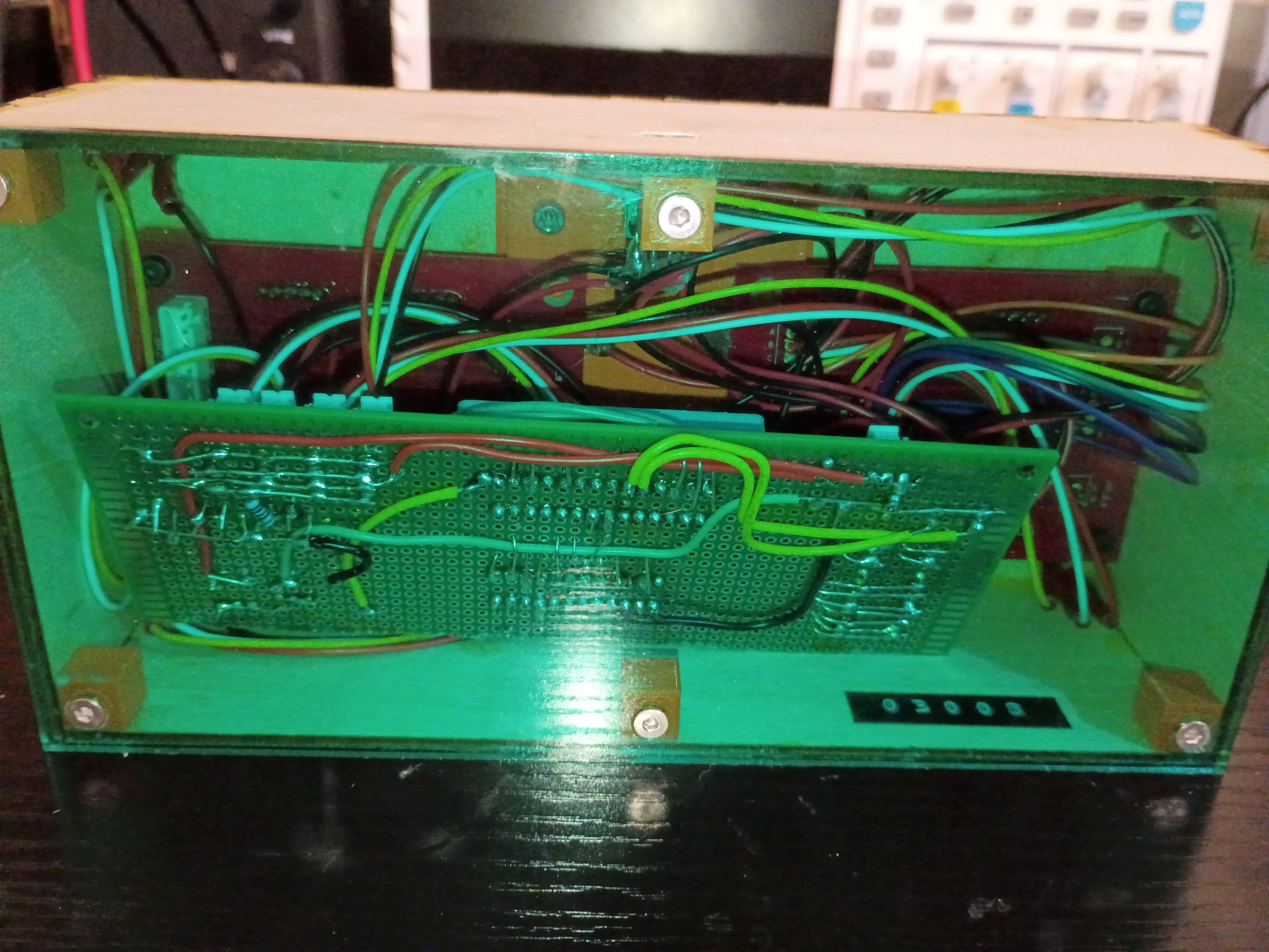
Updated the full project code. Entire project essentially works - including the buzzer, RNG, LEDs, magnetic inputs, etc. See video of it in action. Still needs an improved input block and there is still a glitch where it sometimes initializes with 88/88 on the displays.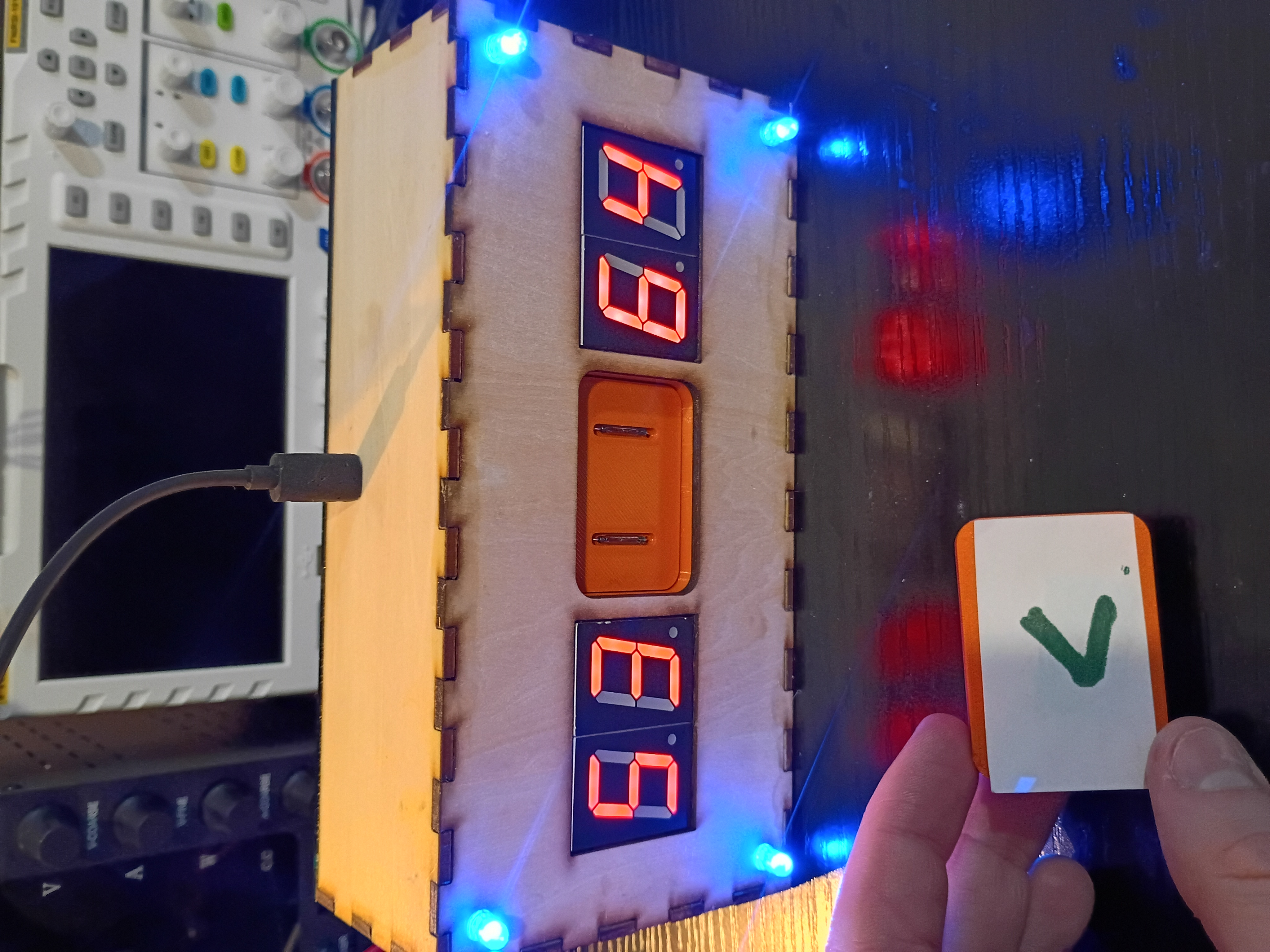
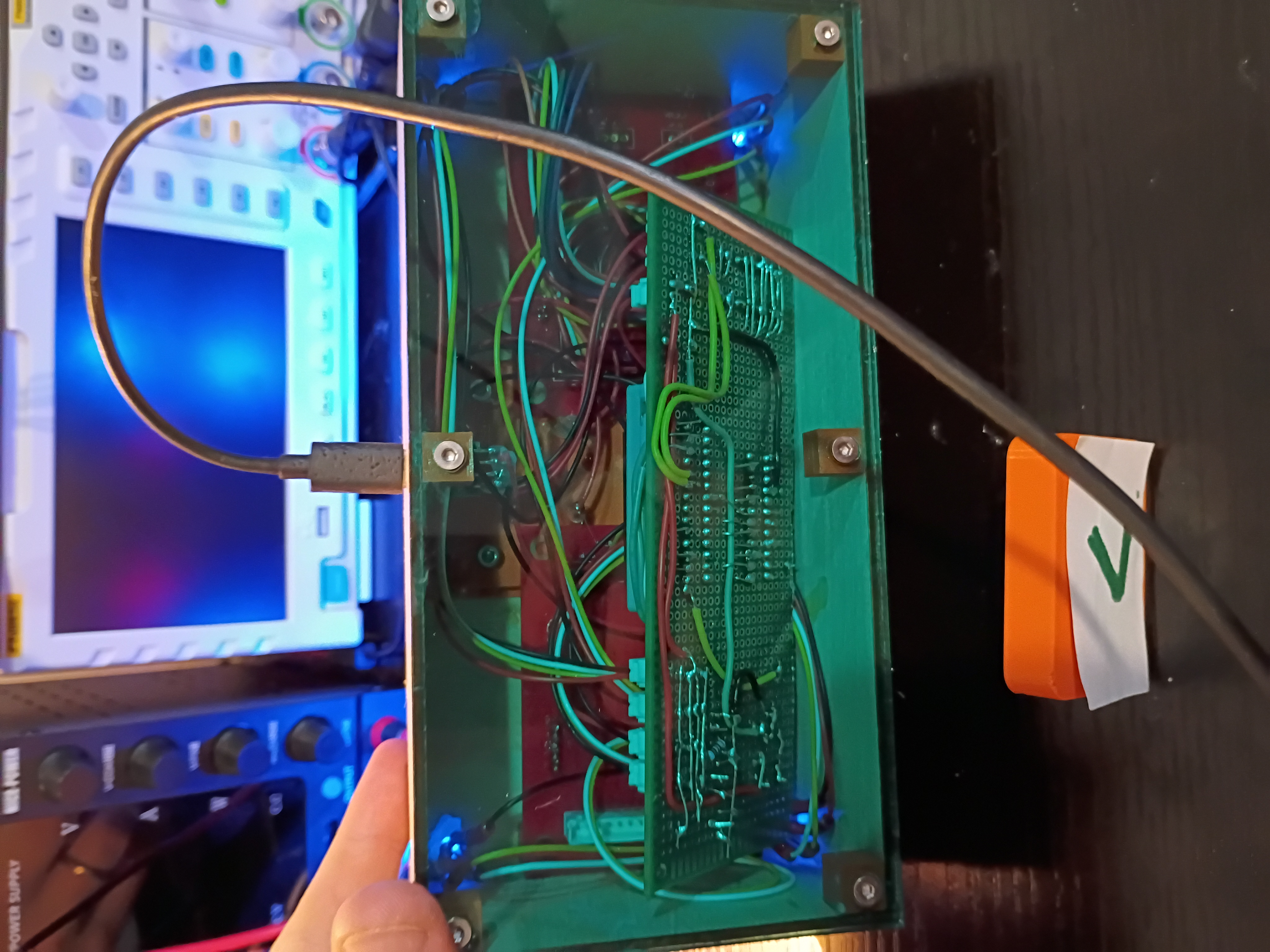
Toyed around with the code for a while, but there is something amiss with the buzzer control timer and the rest of the control logic, so I implemented a buzzer-less version. Had to improve the solder connections, but everything fits in the box pretty well. Needs to be cleaned up slightly. See video of it in action. 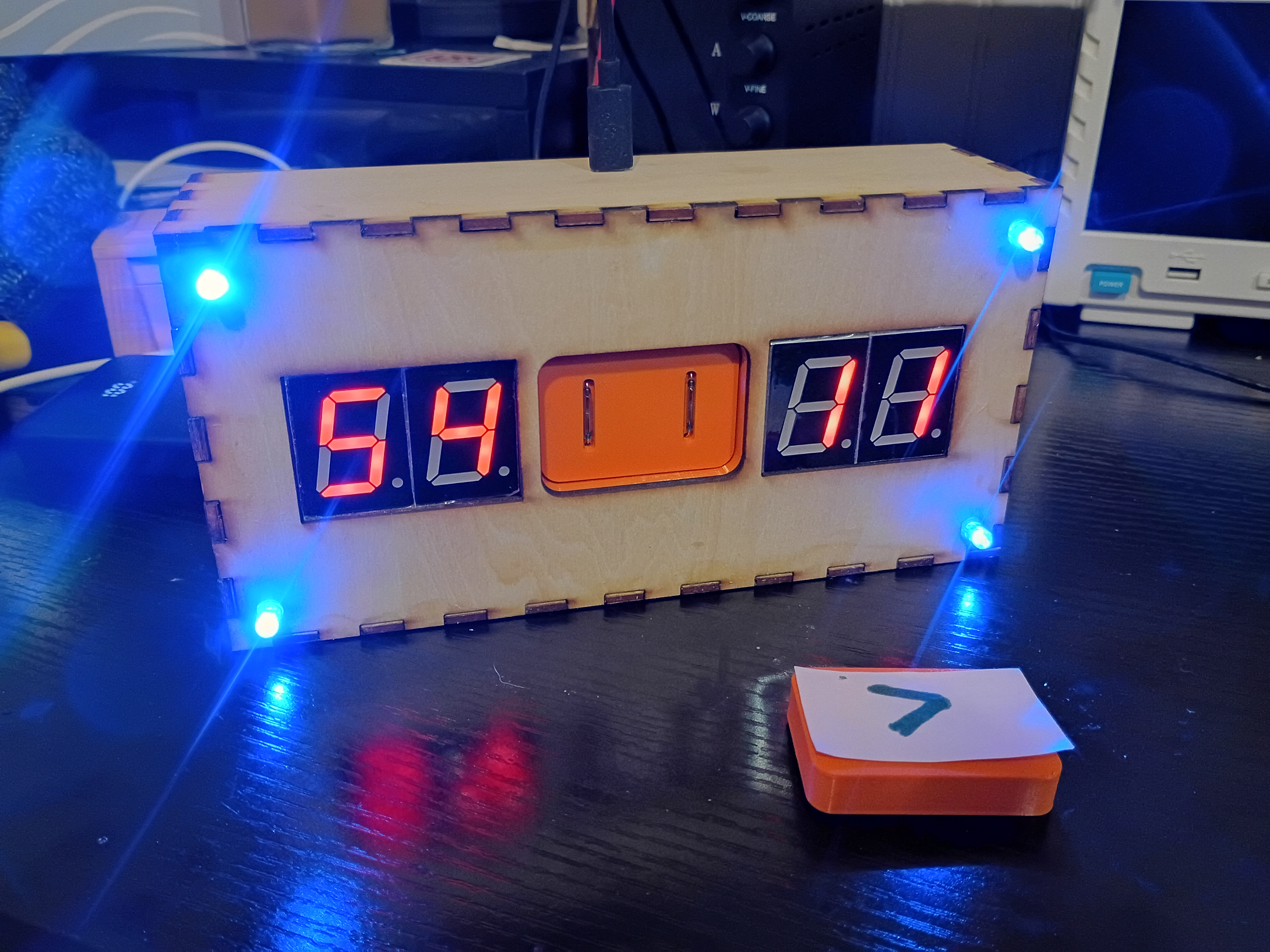
After 2.5 weeks, received 03008-006 PCBs from DKRed. Board quality very good, no mistakes were made on my end or theirs. Silkscreen font kind of squiggly in places. Overall experience was positive, though very slow. They sent 2 extra boards (6 instead of 4). Should probably make the thru holes slightly larger next time. Soldered 7-segments and JST connectors to the PCB and tested some sample code to display digits. There is some software/hardware glitch that is interfering with the buzzer and LEDs. Also, had to hand-crimp the individual JST metal pins to each wire using needle-nose pliers, as the junky JST crimpers I purchased are terrible. I also prepared two additional boards to be shipped out to support the 03009 project. 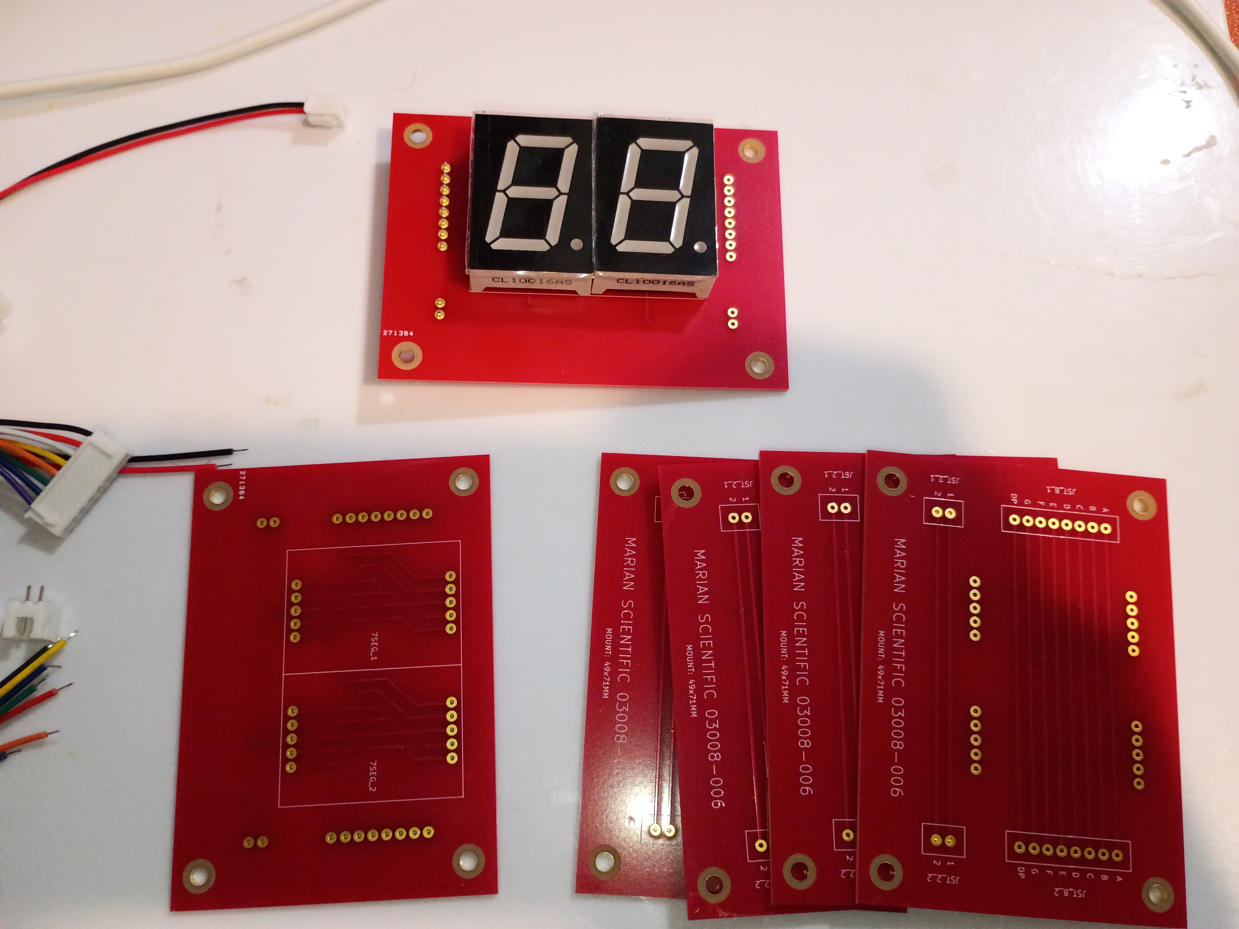
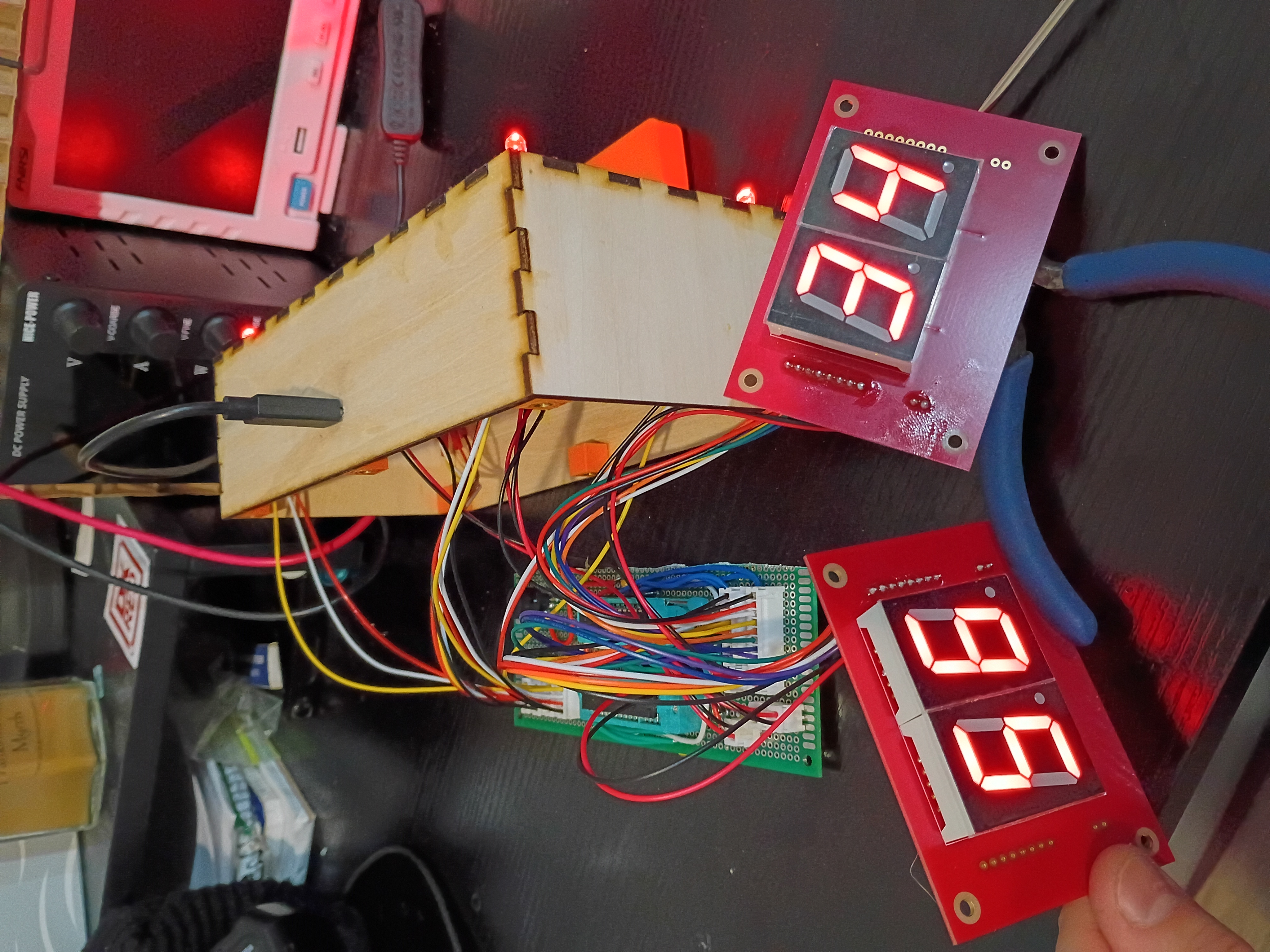
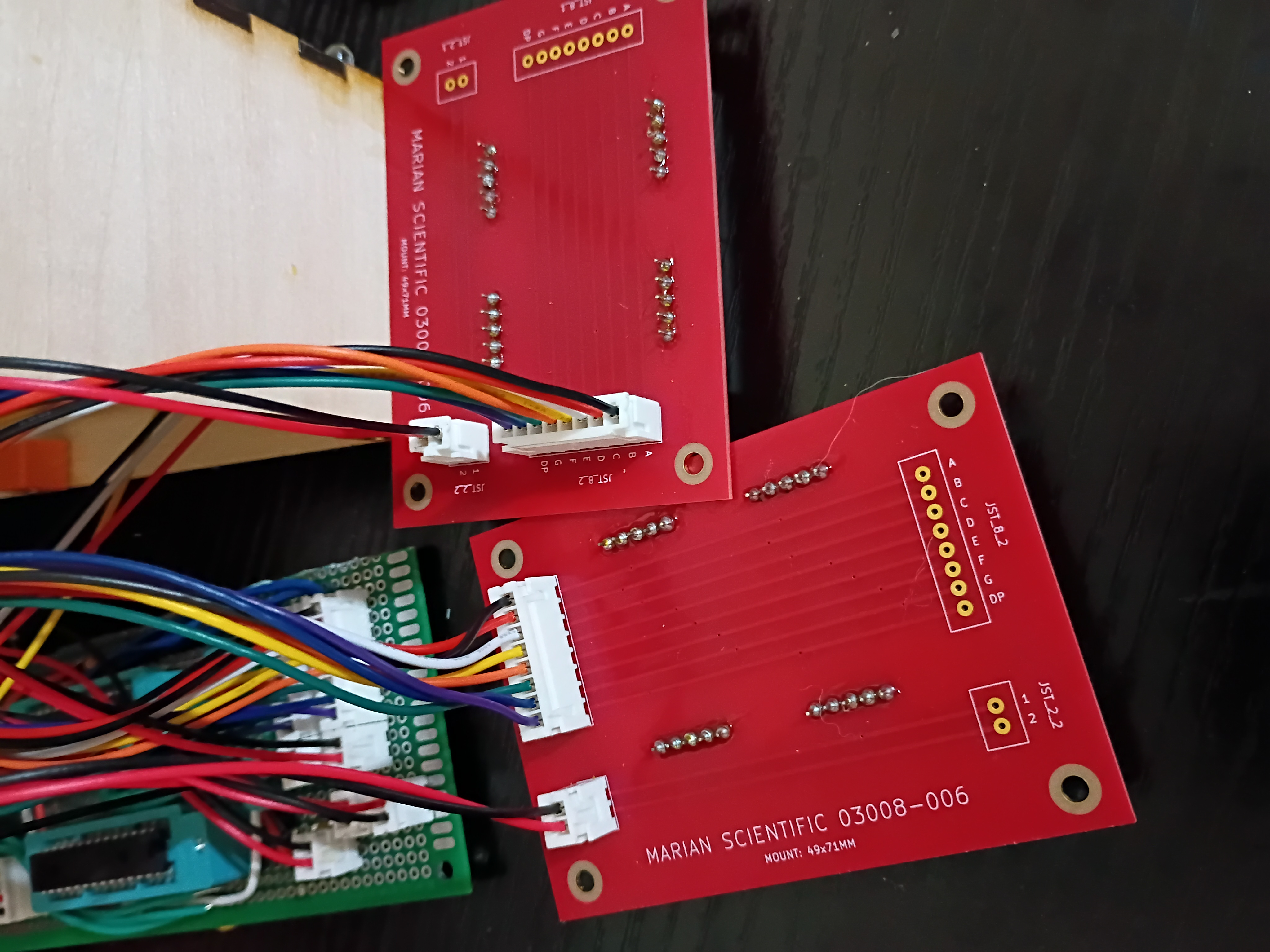
Behold a rasterized version of my 'Alligreater' SVG to be either laser engraved cut or printed/laminated/pasted to the front of the magnet block. 
Put final counterbores into X-Y gantry plate and test-fit the linear rails and ballscrew ball nut carriage block. Somehow miraculously everything is aligned. I do still need to put in tapped M5 mounting holes for attaching things. 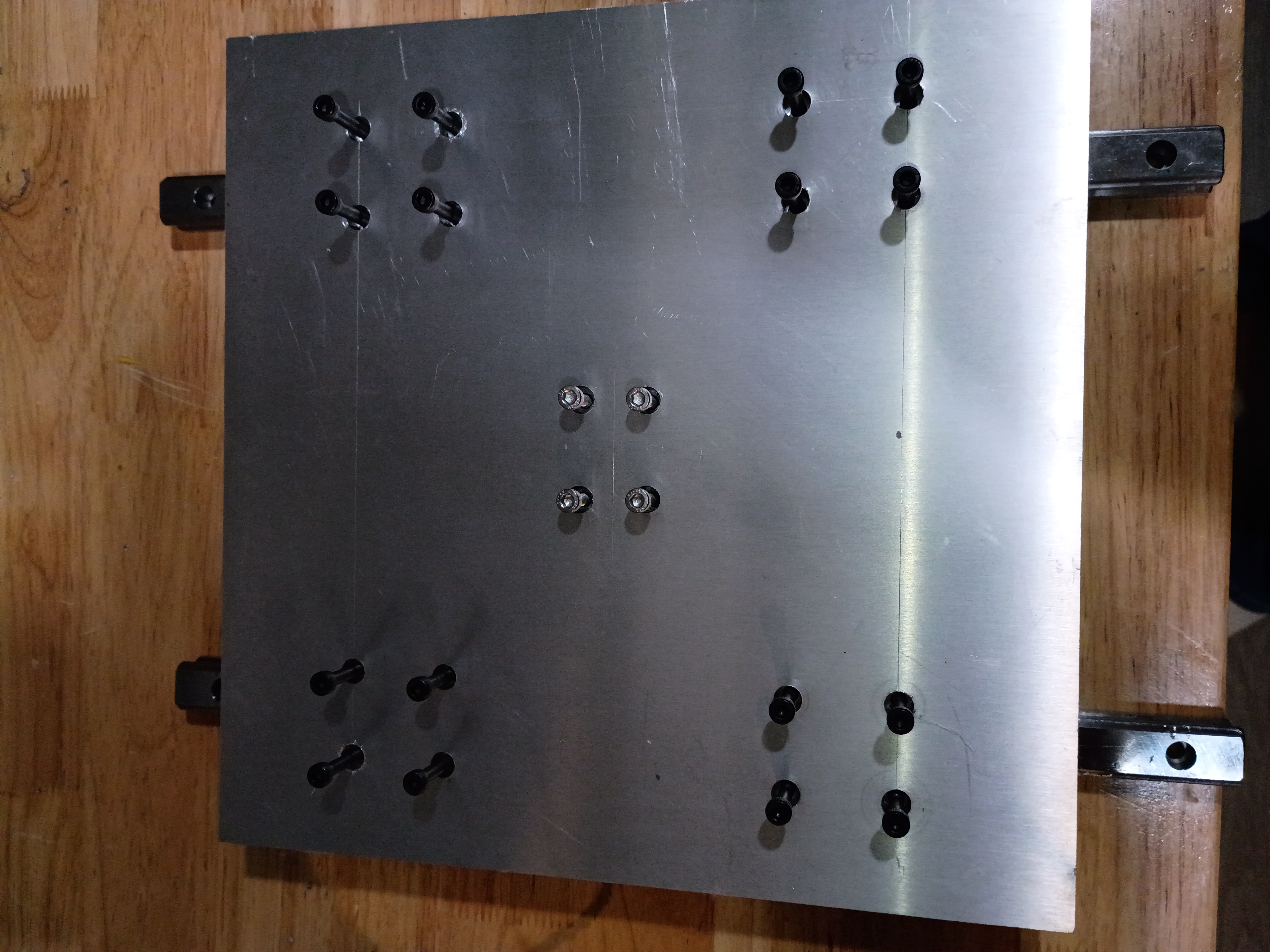
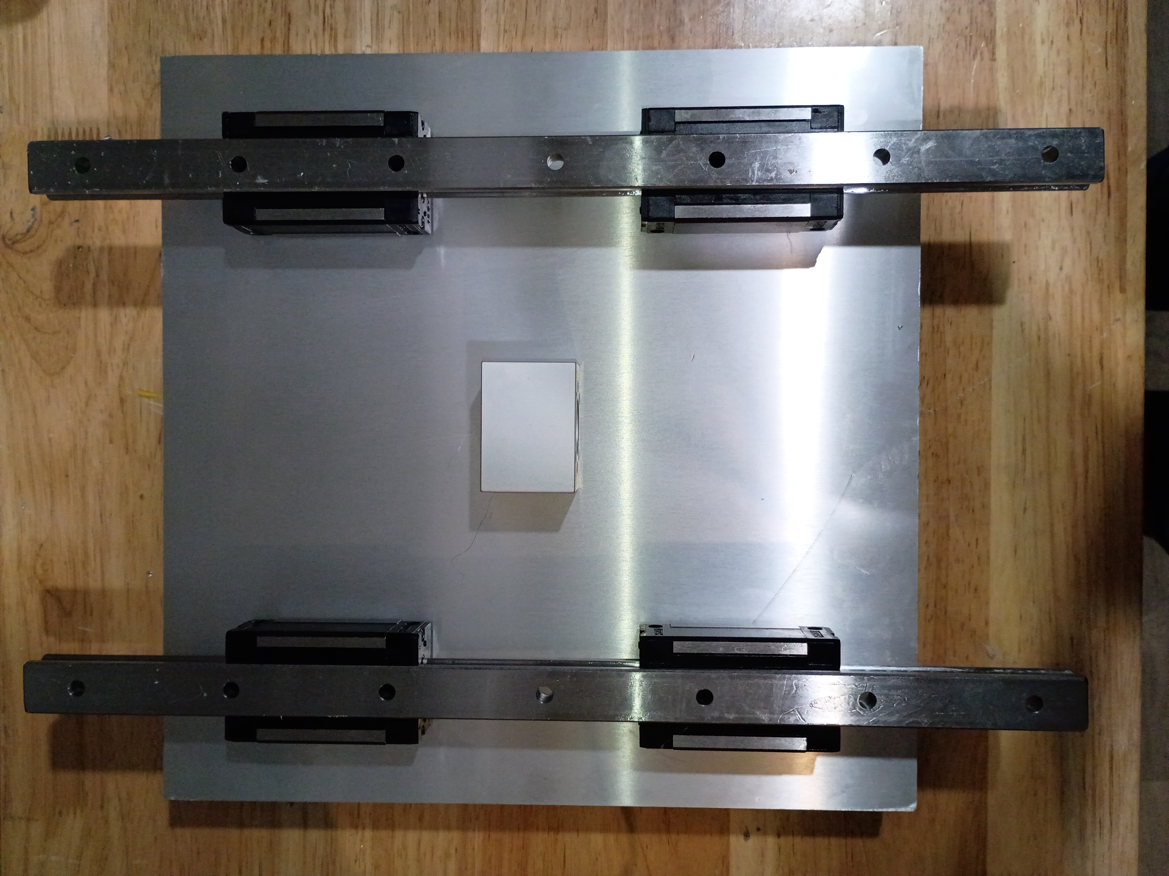
Compiled the full project code from the minimum viable test cases, but I am unable to test it easily until USPS delivers the 7-segment breakout PCBs, which were supposed to be delivered yesterday.
Threw a quick GPS data display together using a Pi Zero (overkill, used only for the USB GPS dongle). It shows lat/long/alt/speed and the fix status and number of satellites observed. 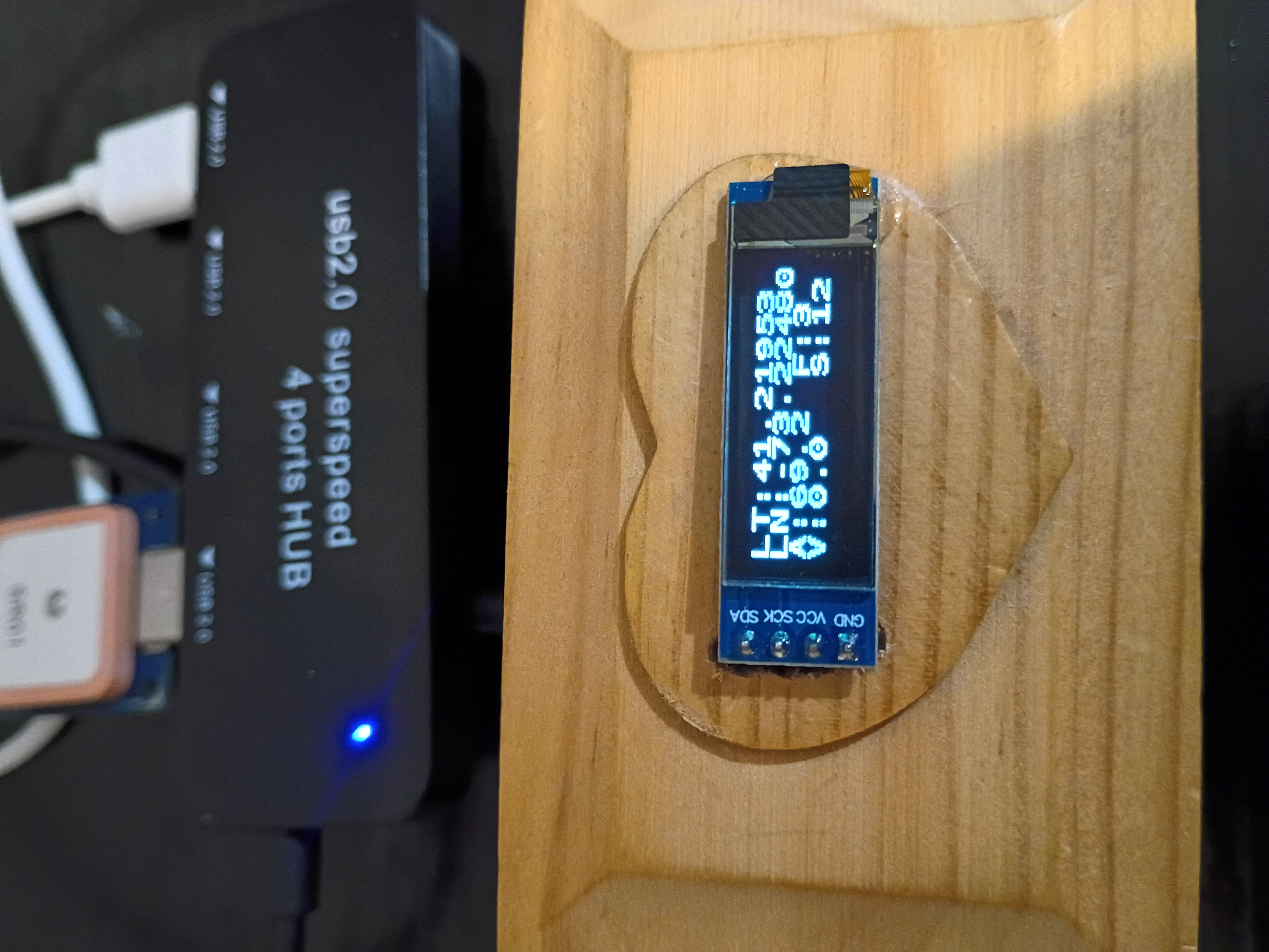
I updated the web journal-generating script to add some additional info and formatting.
Began to drill and counterbore mounting holes for the X-Y gantry plate. These slotting counterbore bits are really nice but get gummed up quickly and stall the motor of my weak drill press. Also have to use a cordless drill to reach the central holes. Would be nice to make a nice drill press. 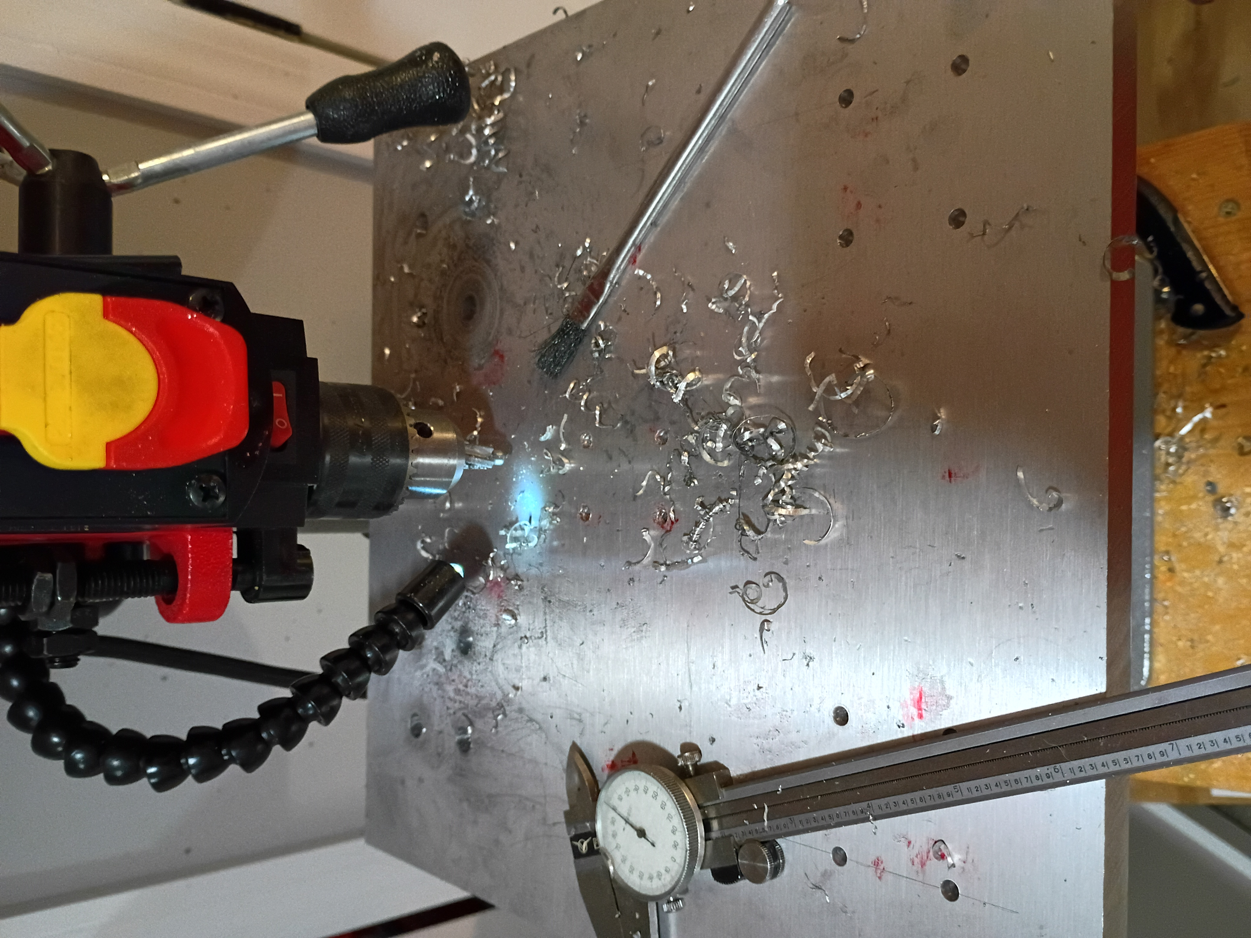
Took inventory of CNC mill project after long hiatus. Updated CAD model to reflect length of installed collet and bit and migrated to organization repository. Marked out the drill and tap locations for the X-Y gantry plate. 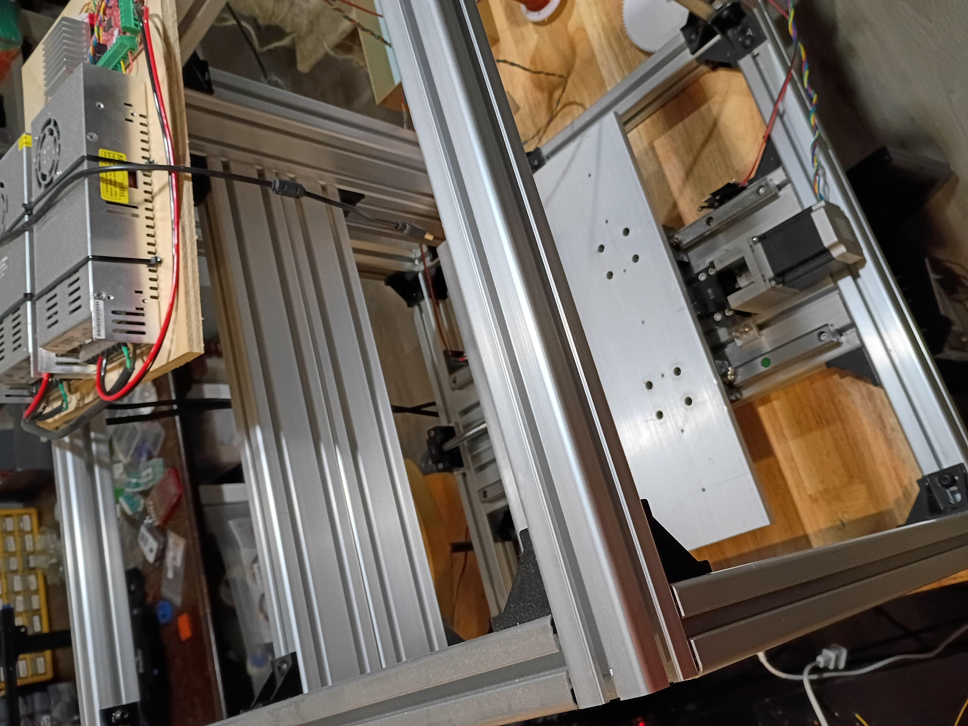
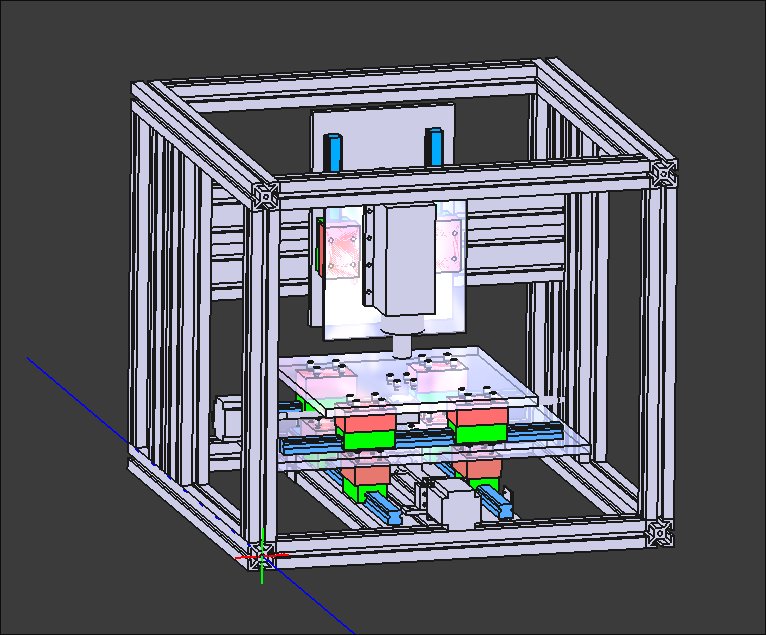
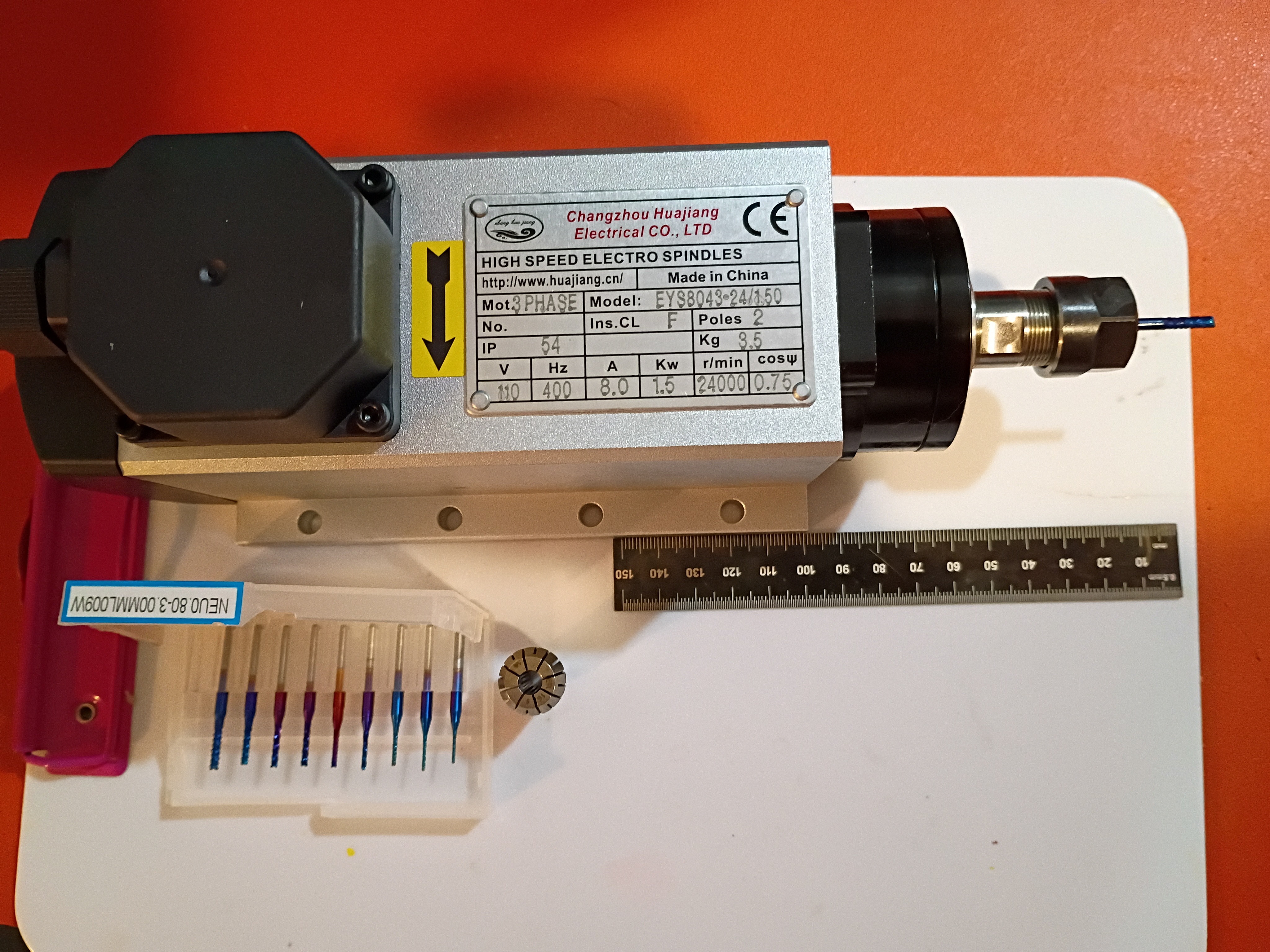
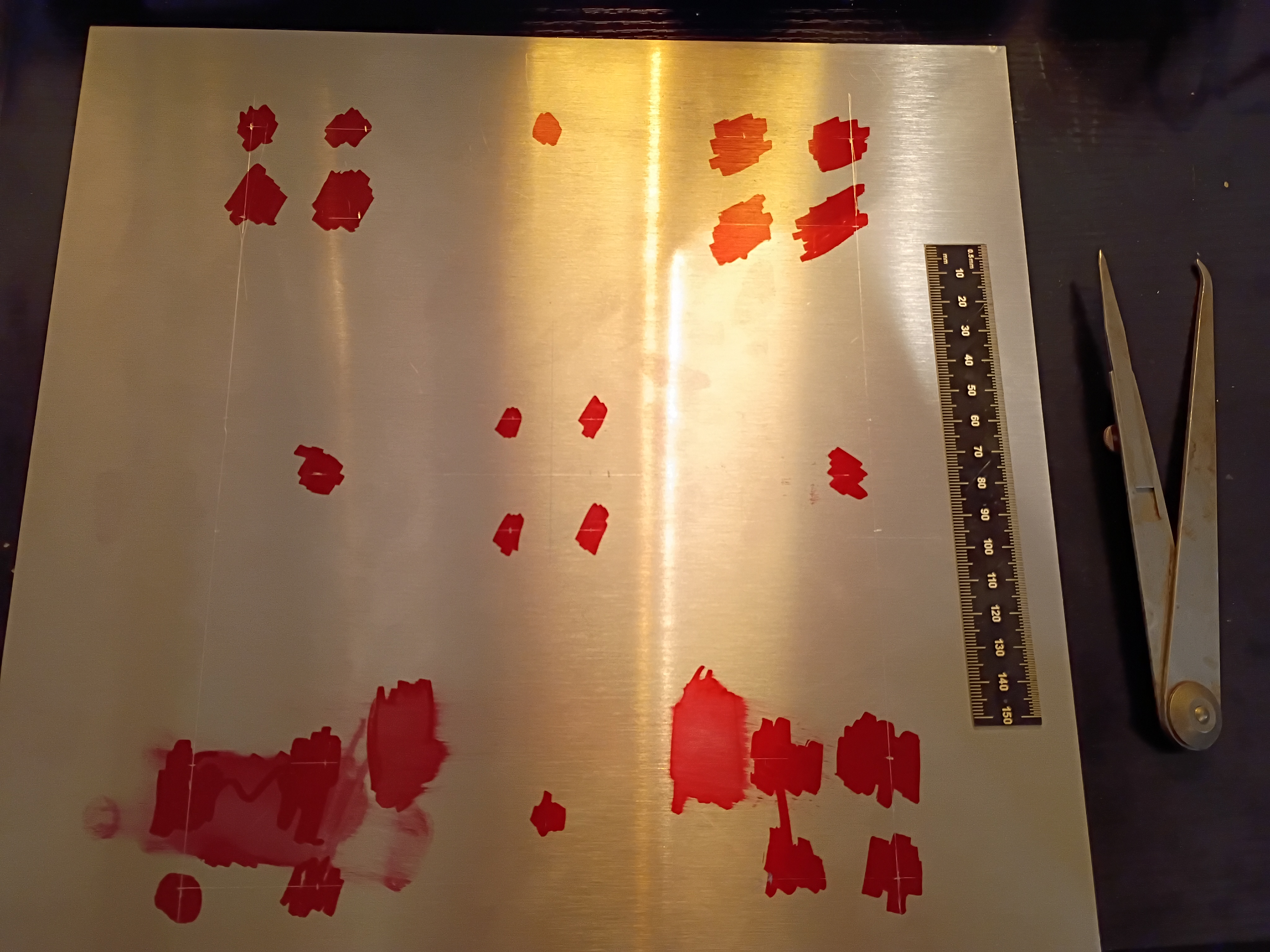
Snipped down main circuitboard to fit snuggly inside the box. Debugged minor soldering issue with one of the RGB LEDs. Wrote this code to control the lights in unison with the buzzer depending on the reed switch status. See video example. 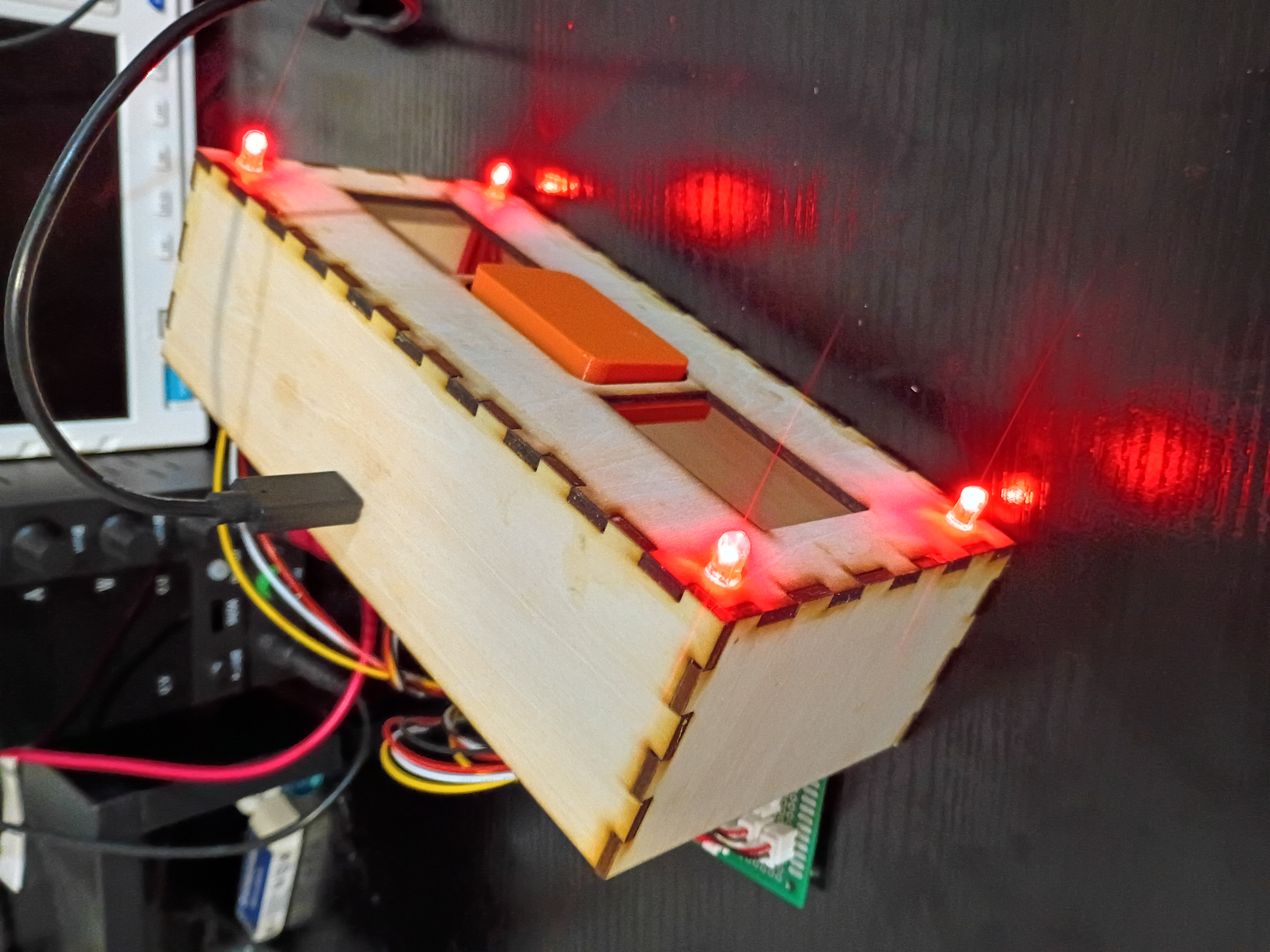
Designed and ordered 6x stepper motor driver PCBs from OSHPark to compare against DKRed. See CAD files. Submission was seamless, and they give better visibility into the order timeline. Pricing is comparable to DKRed. I decided not to expedite. 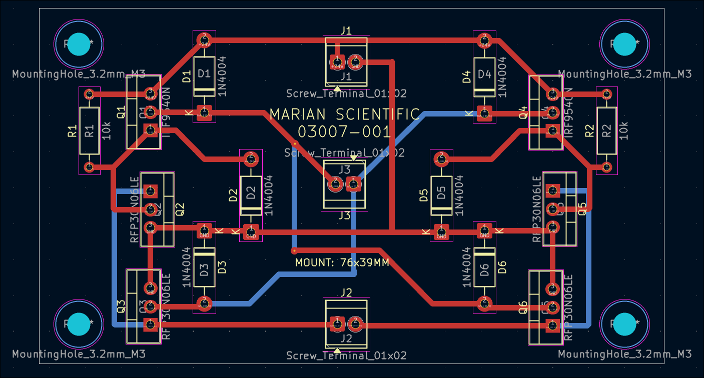
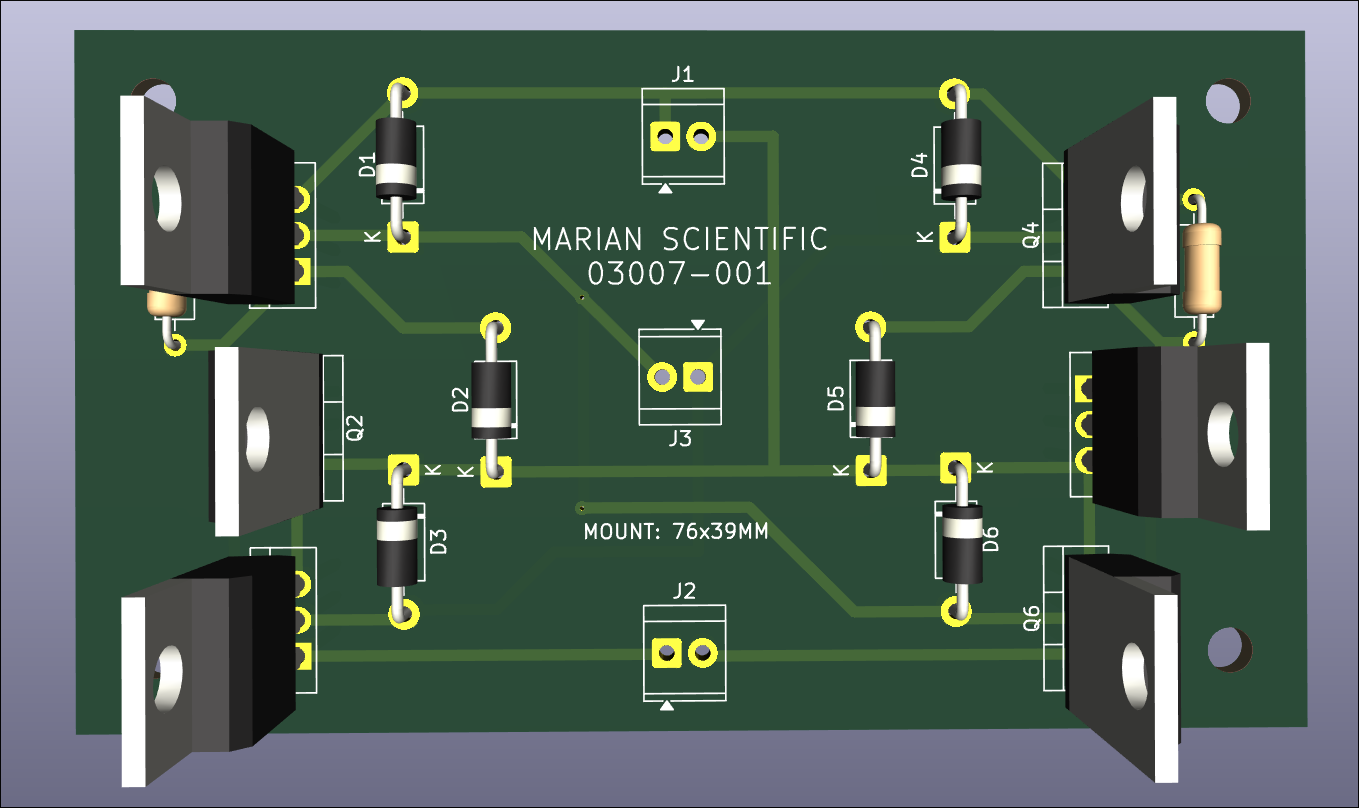
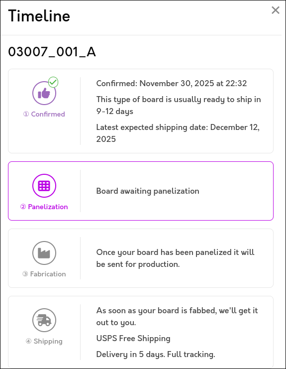
I updated the web journal-generating script to categorize entries by submission month and reorganize the main page by project/author and the most-recent 10 entries. This is to improve page load times. A similar monthwise breakout eventually needs to be done at the author-level as well.
Reprinted magnet block with 2 holes to accept 2 magnets which must be oriented with opposite polarity facing out for best detection by the reed switches. See example. Also glued mounting blocks for the bottom acrylic plate. 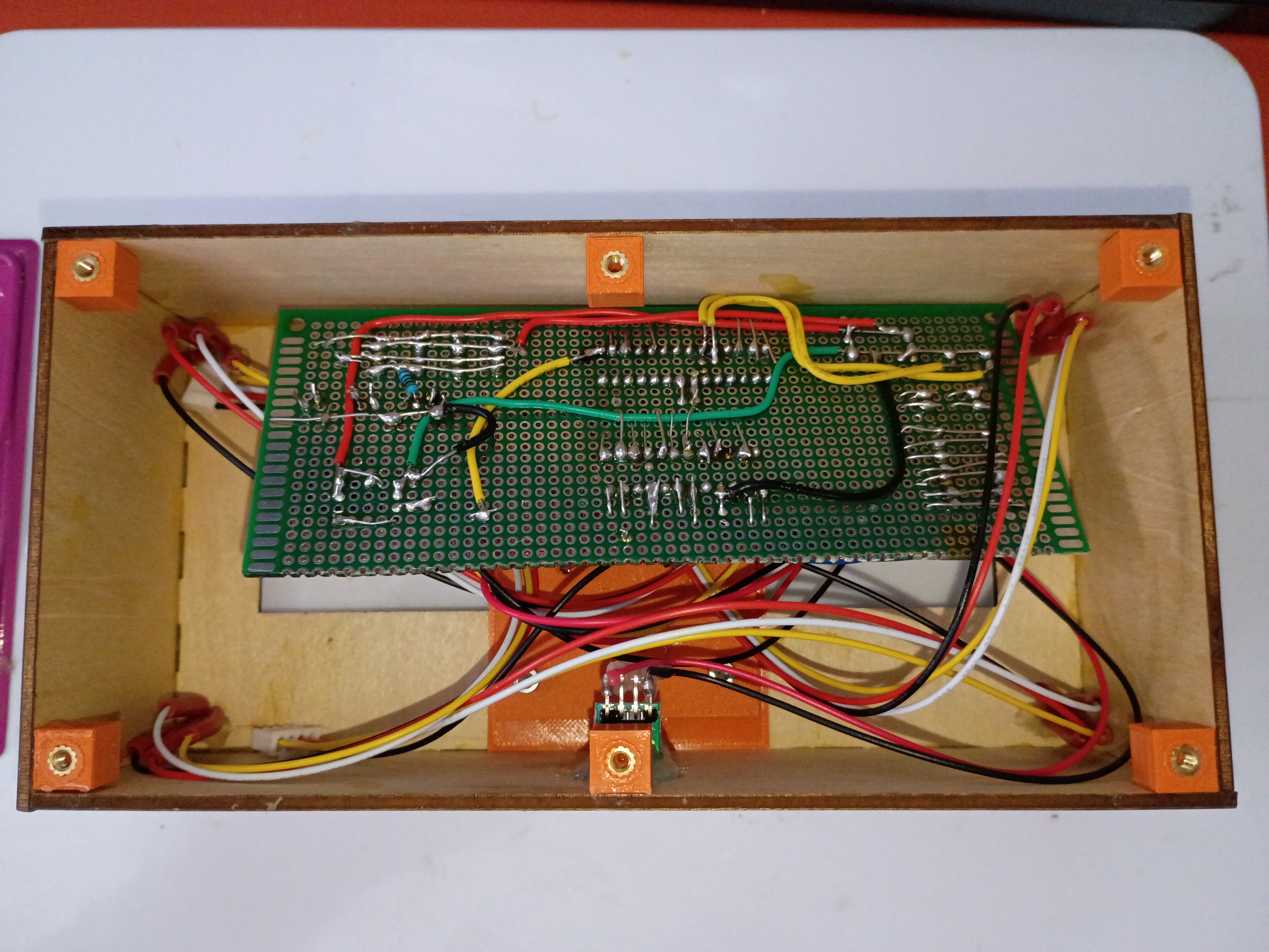
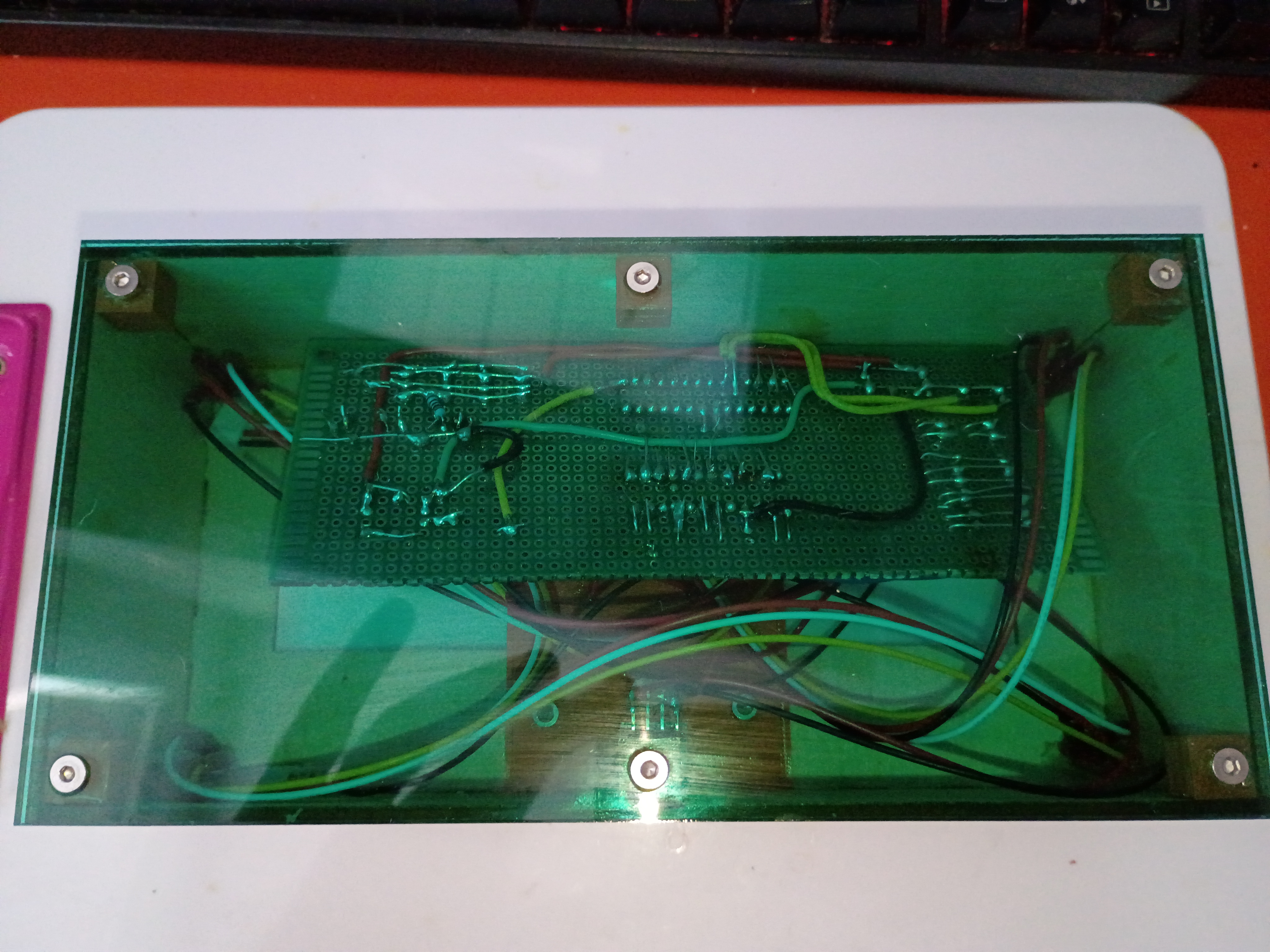
Drilled slot in box and mounted USB-C connector. Mounted, soldered, and heat-shrunk leads to all indicator LEDs and reed switches. Soldered additional JST sockets for the reed switches onto the main circuitboard. Glued box together. Tested magnetic field detection with this C code. 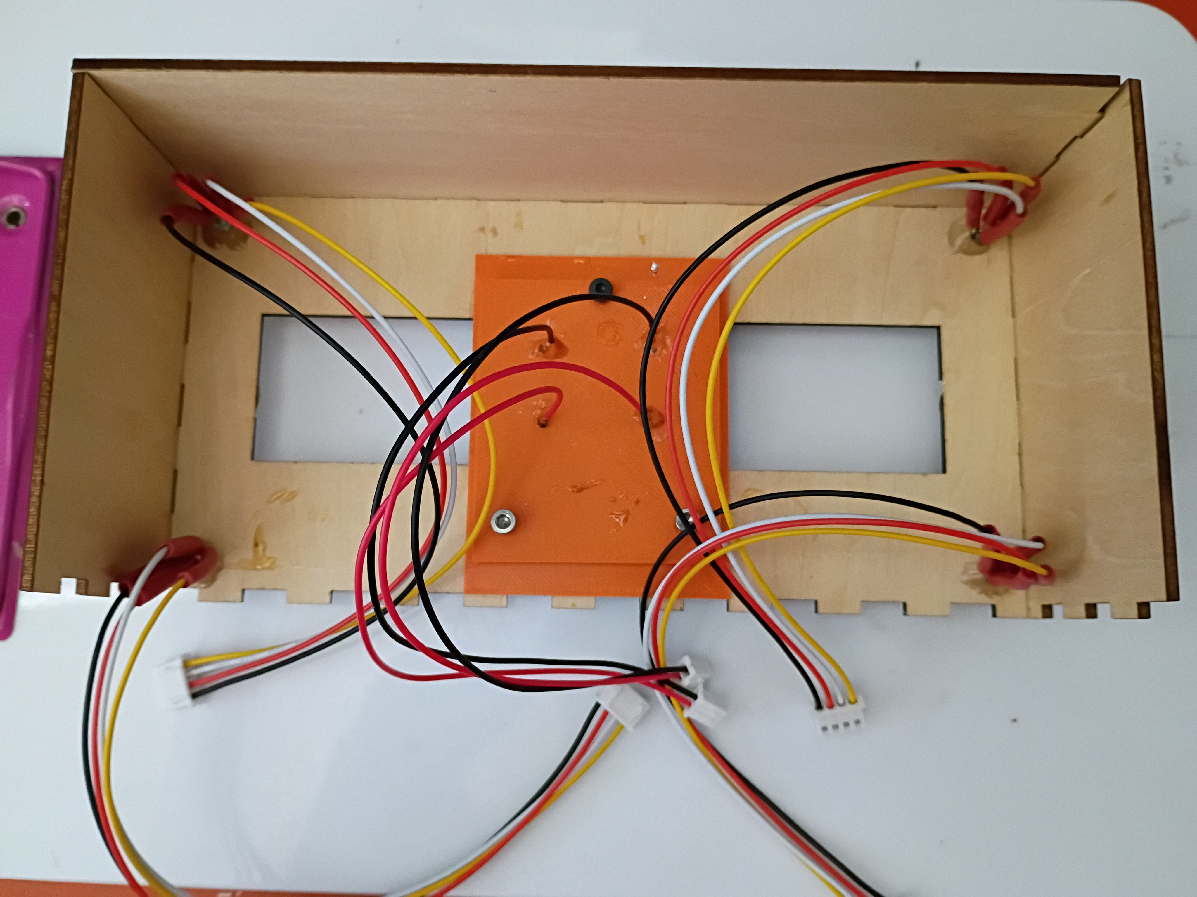
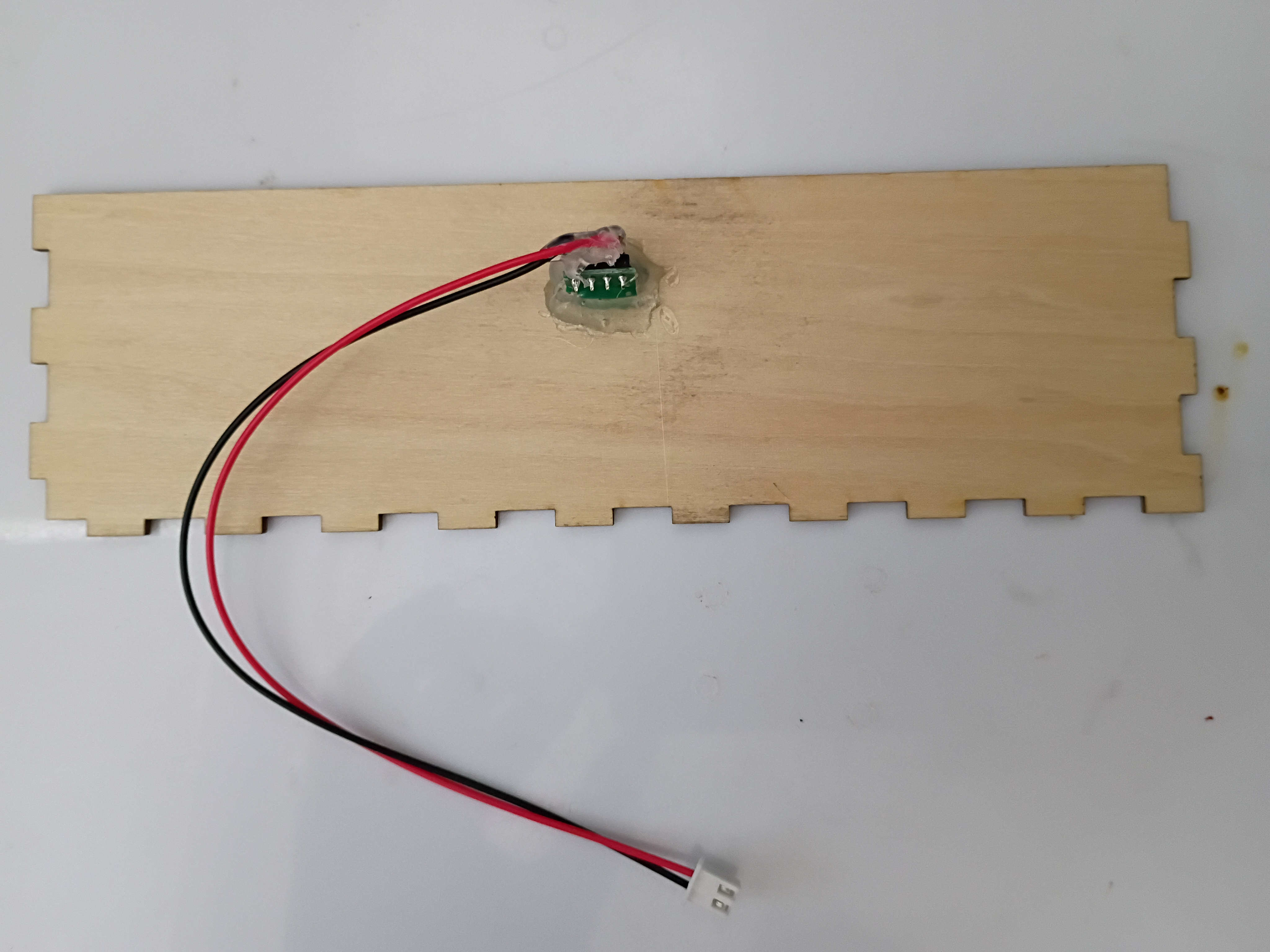
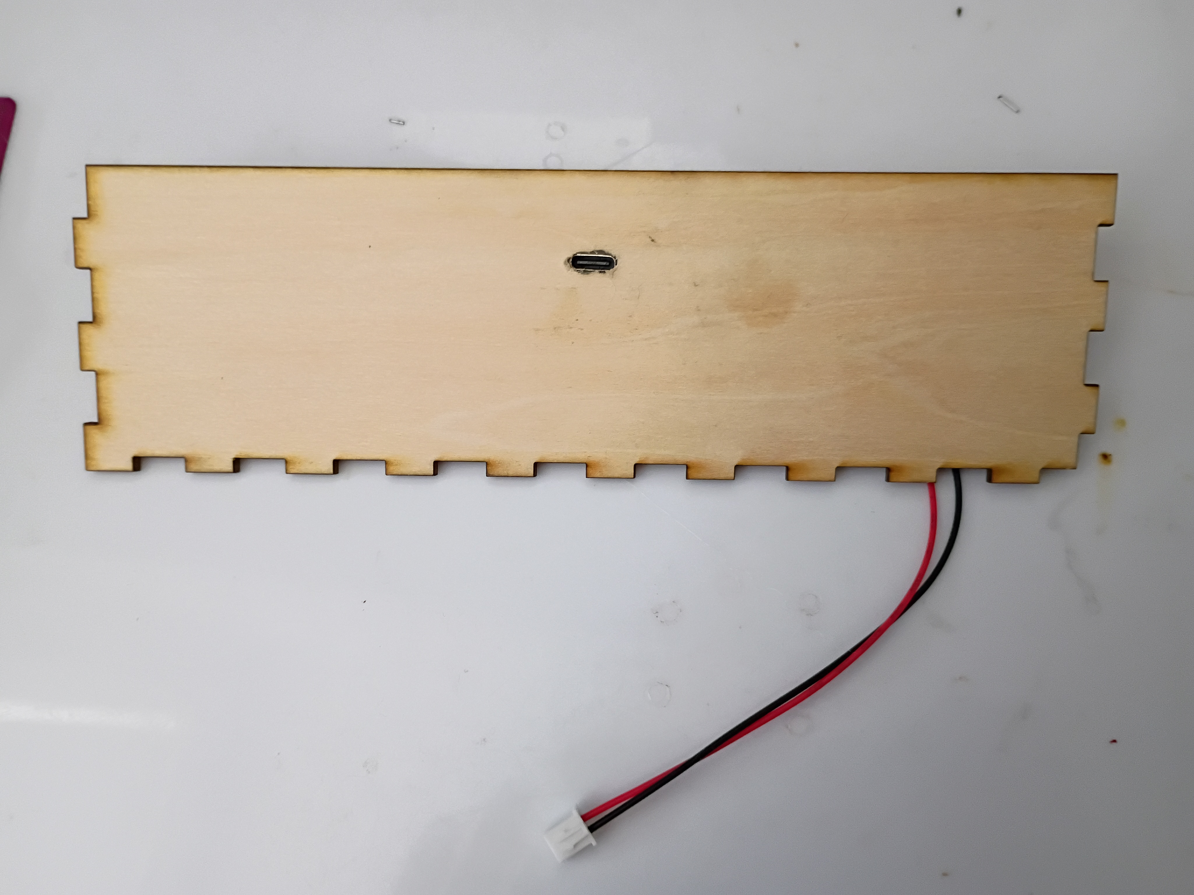
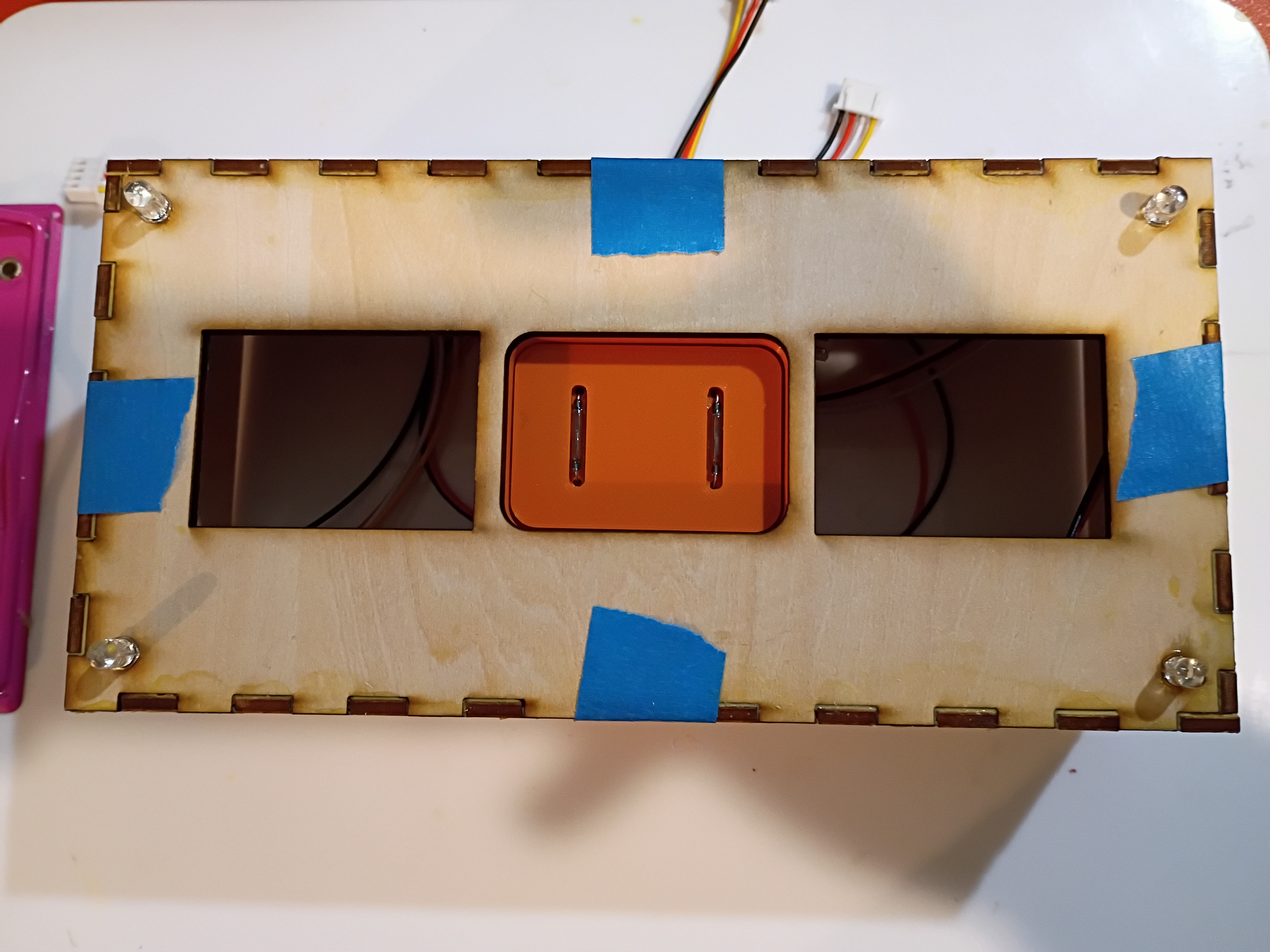
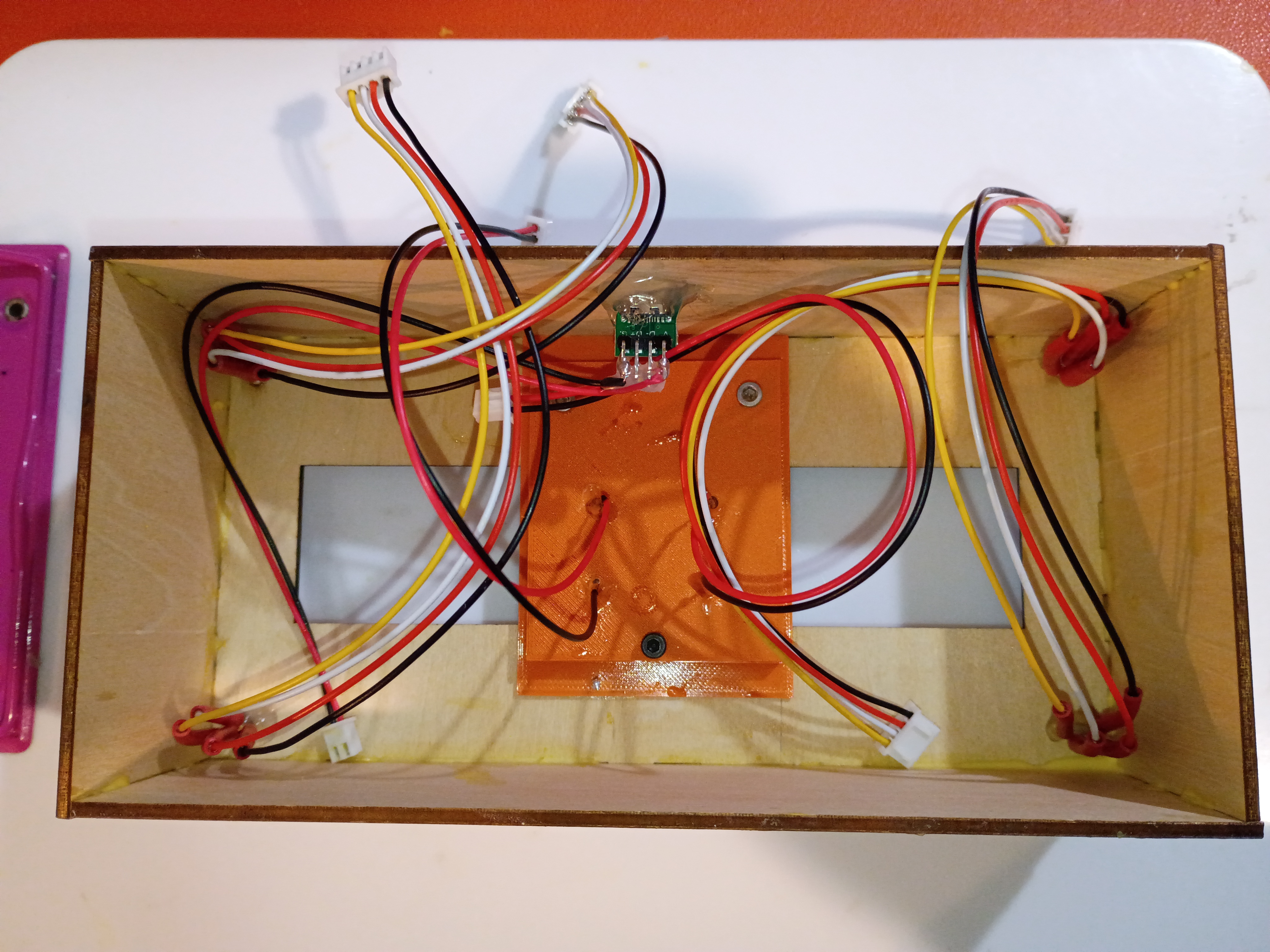
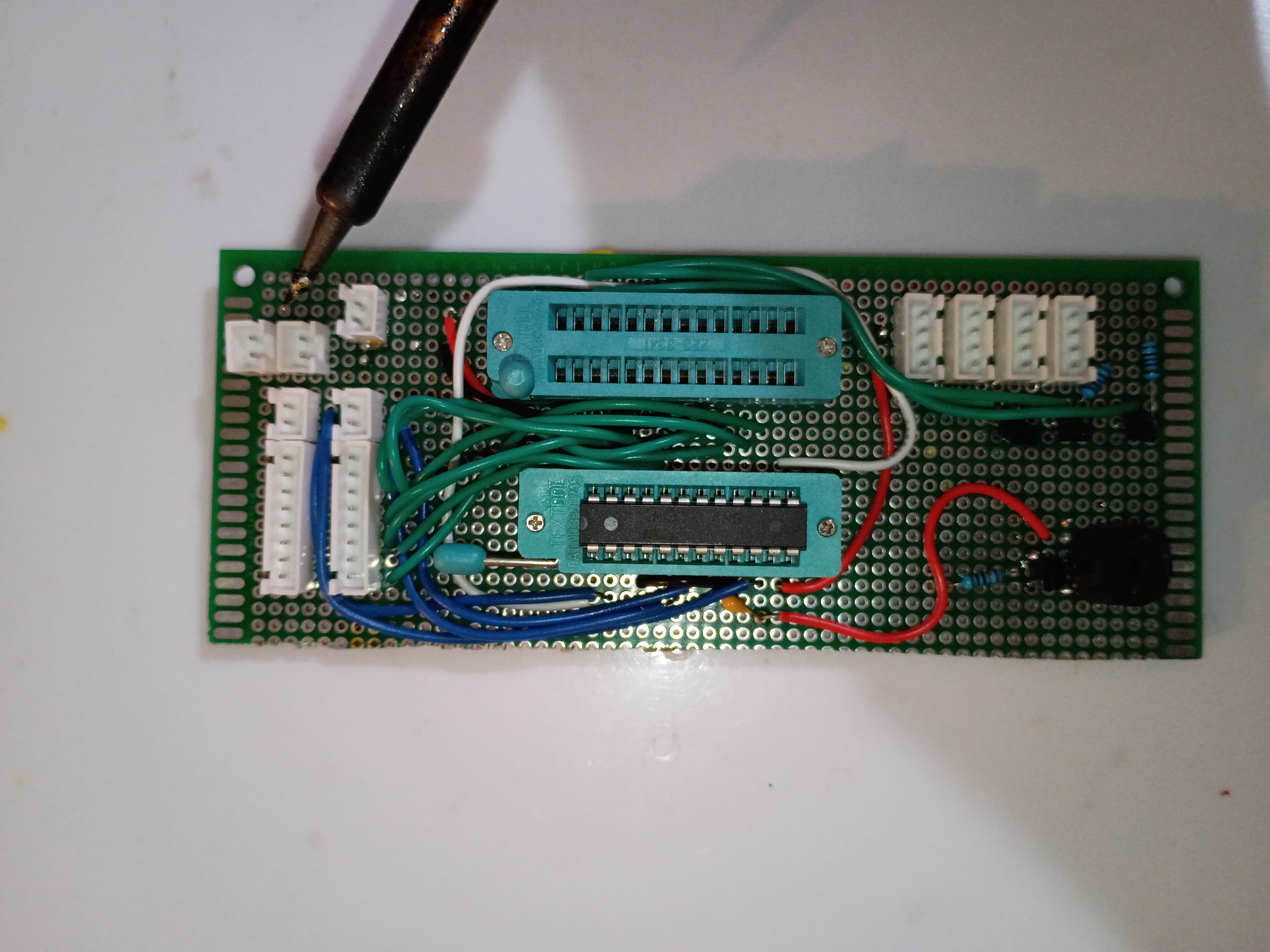
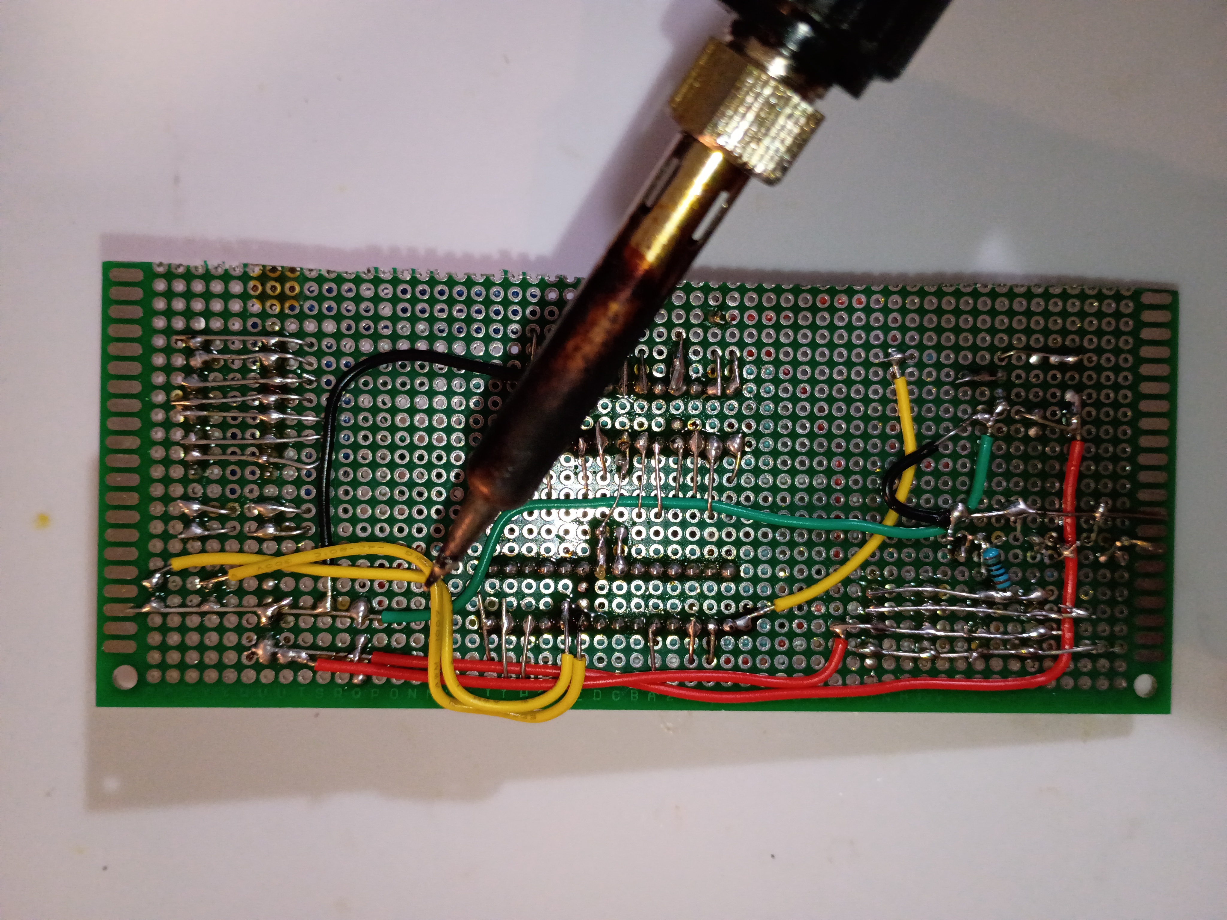
Finished soldering components onto main perfboard. 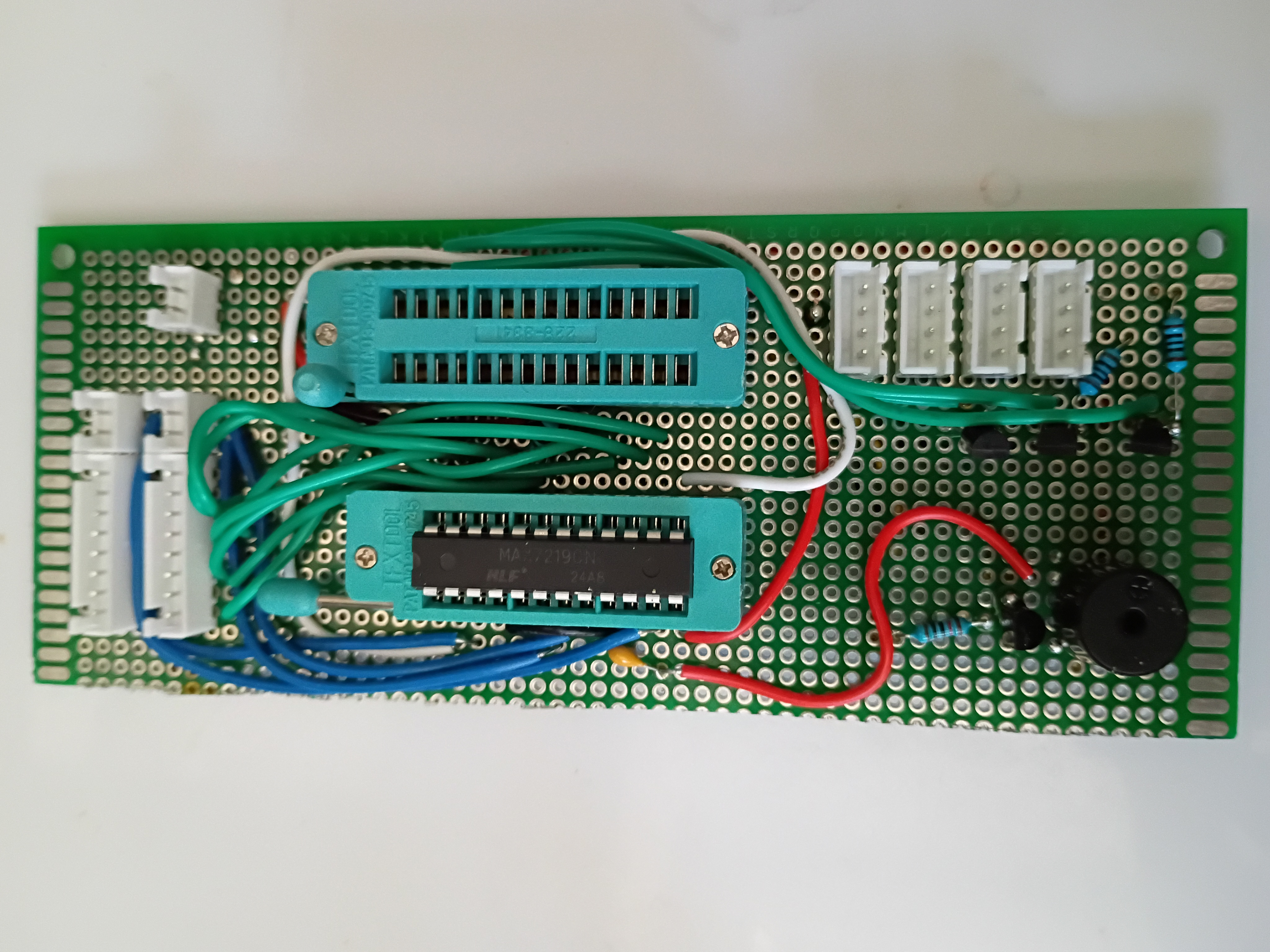
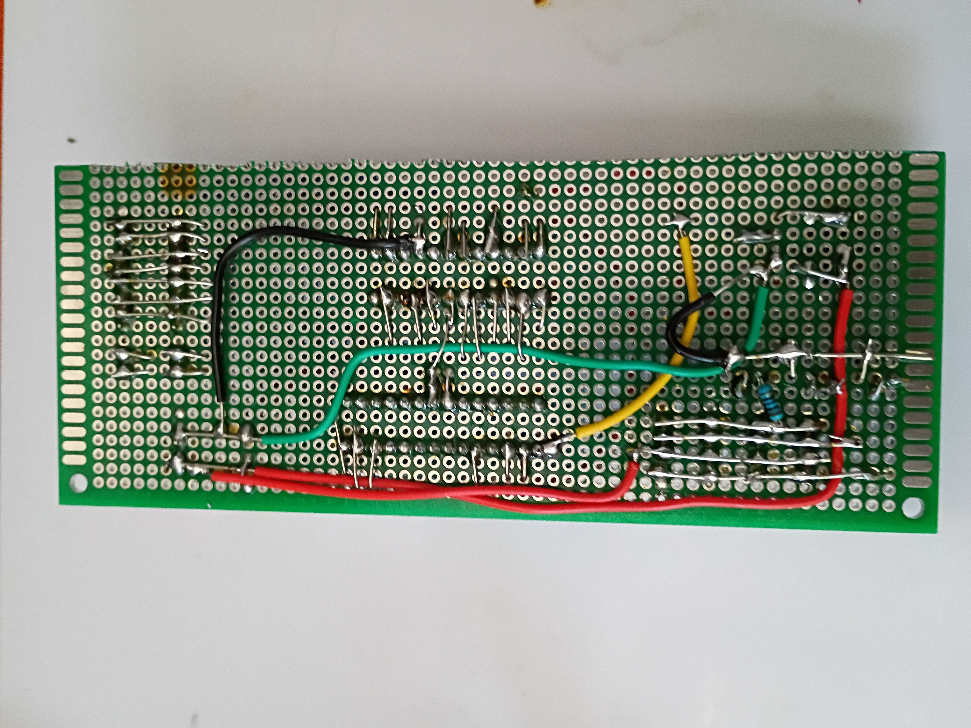
Circuit and code to blink multiple RGB LEDs in unison using 2N7000 mosfets since they draw slightly too much current to be driven by GPIO directly. 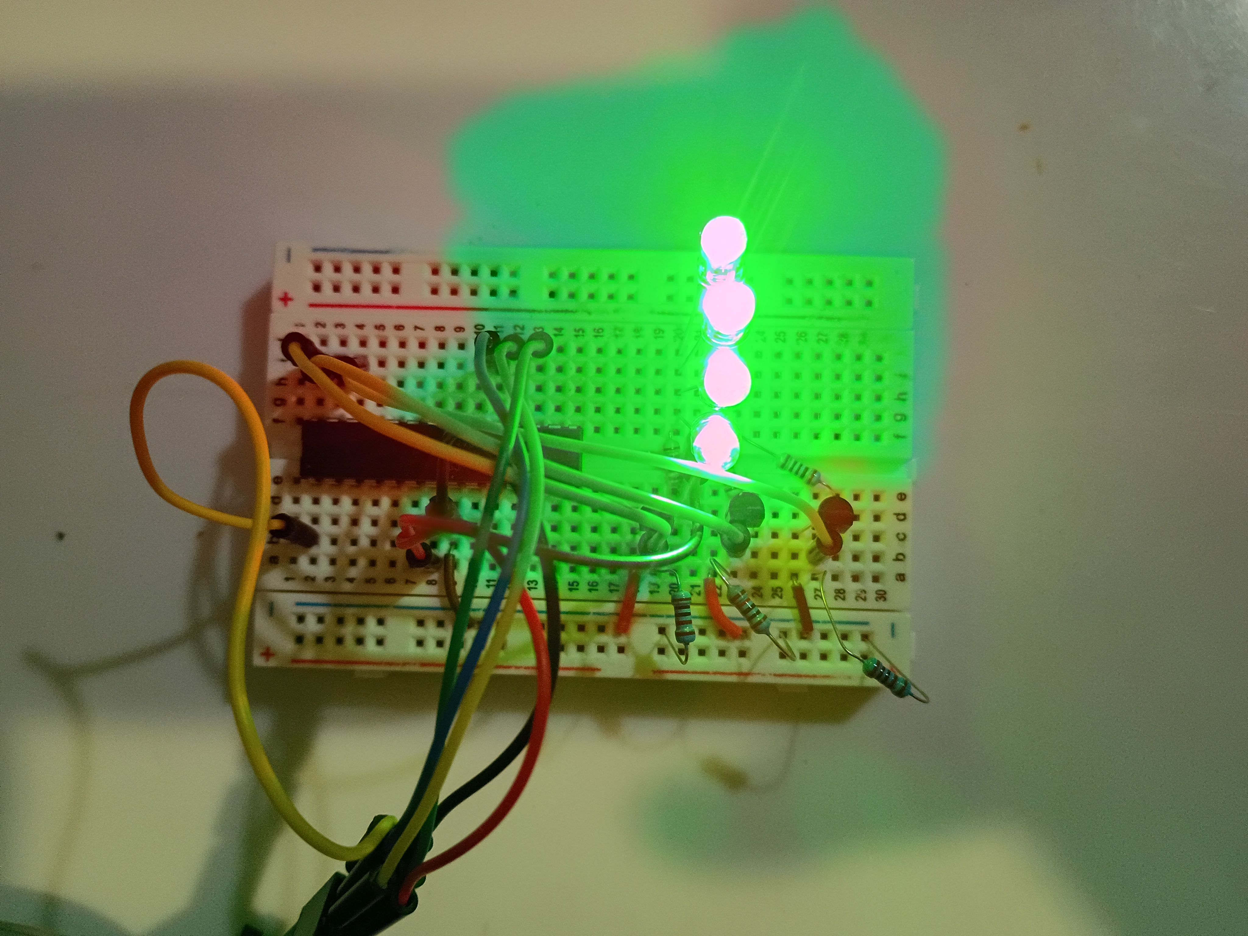
Printed several gear components. Manufacturing recommendation is to make the hole in the hour drive gear all the way thru the part and increase the inner diameter slightly (0.1mm) for better clearance with the minute shaft. Components were assembled and functionality was tested successfully. 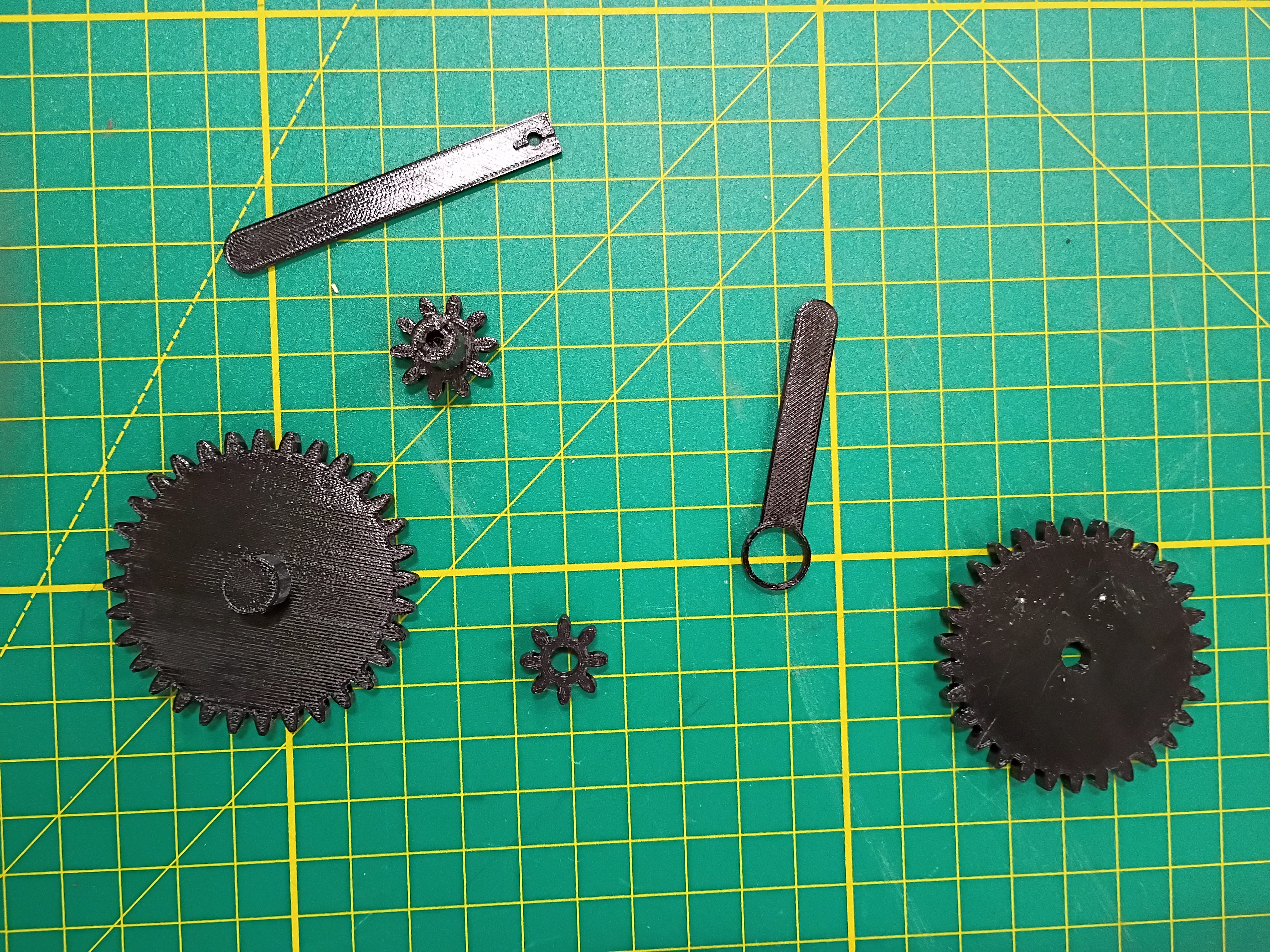
Laser cut 3mm acrylic bottom panel (30% speed, 100% power/current, 45W, only slightly caught fire). Countersunk holes for M3 screws (tendency to shatter, will not do again). Did a dry fit with the rest of the box. Continued to solder more components. 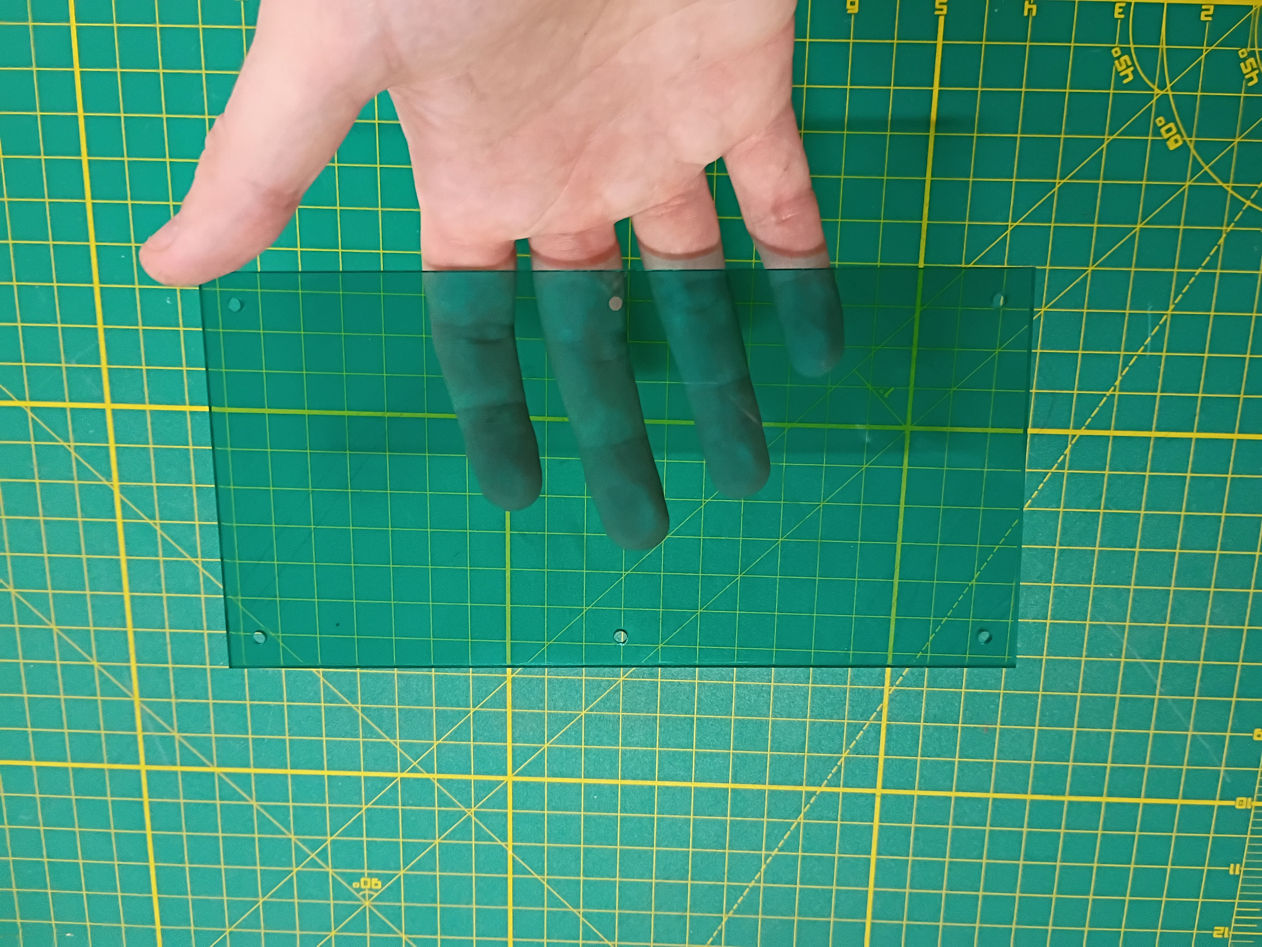
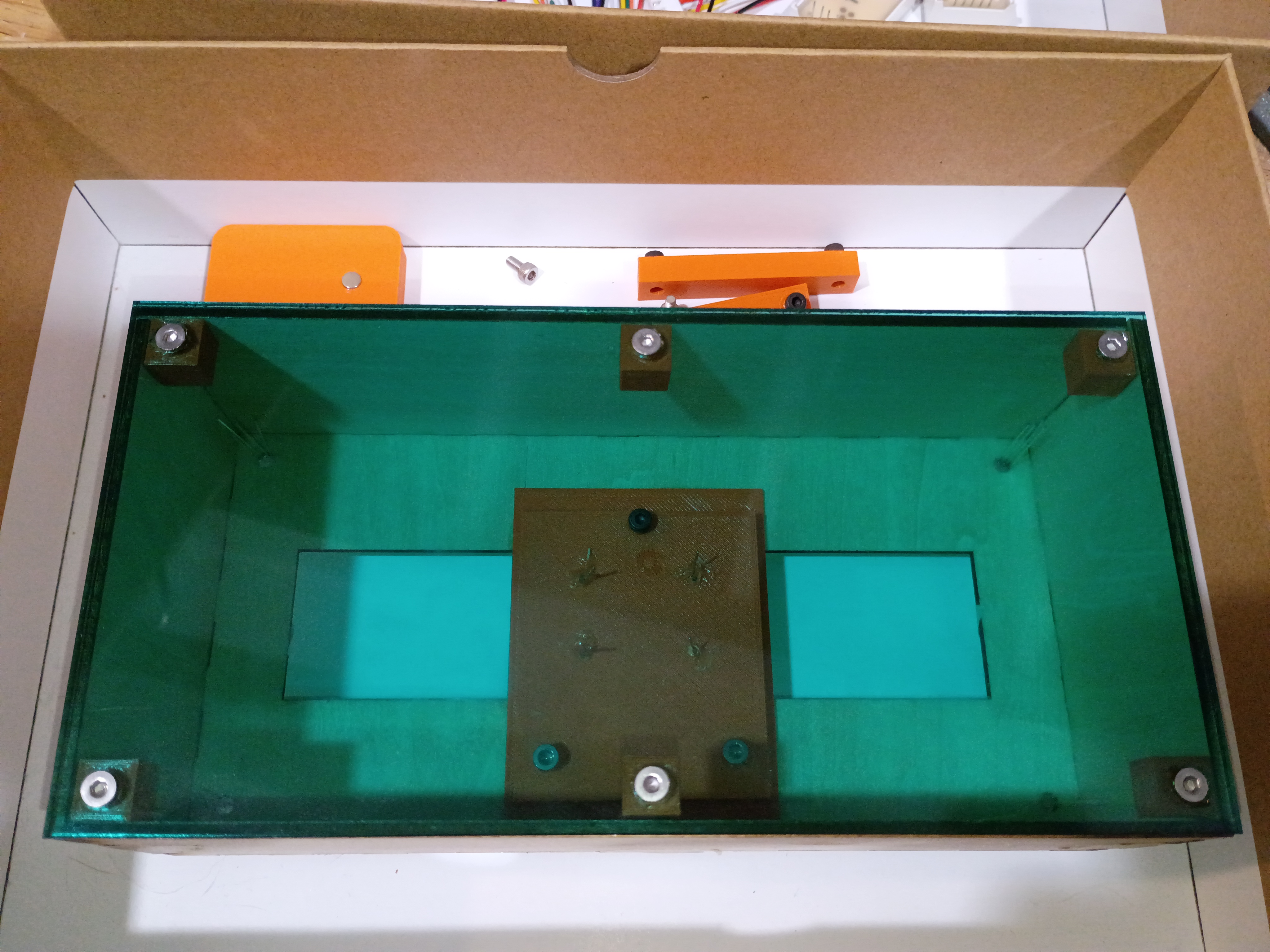
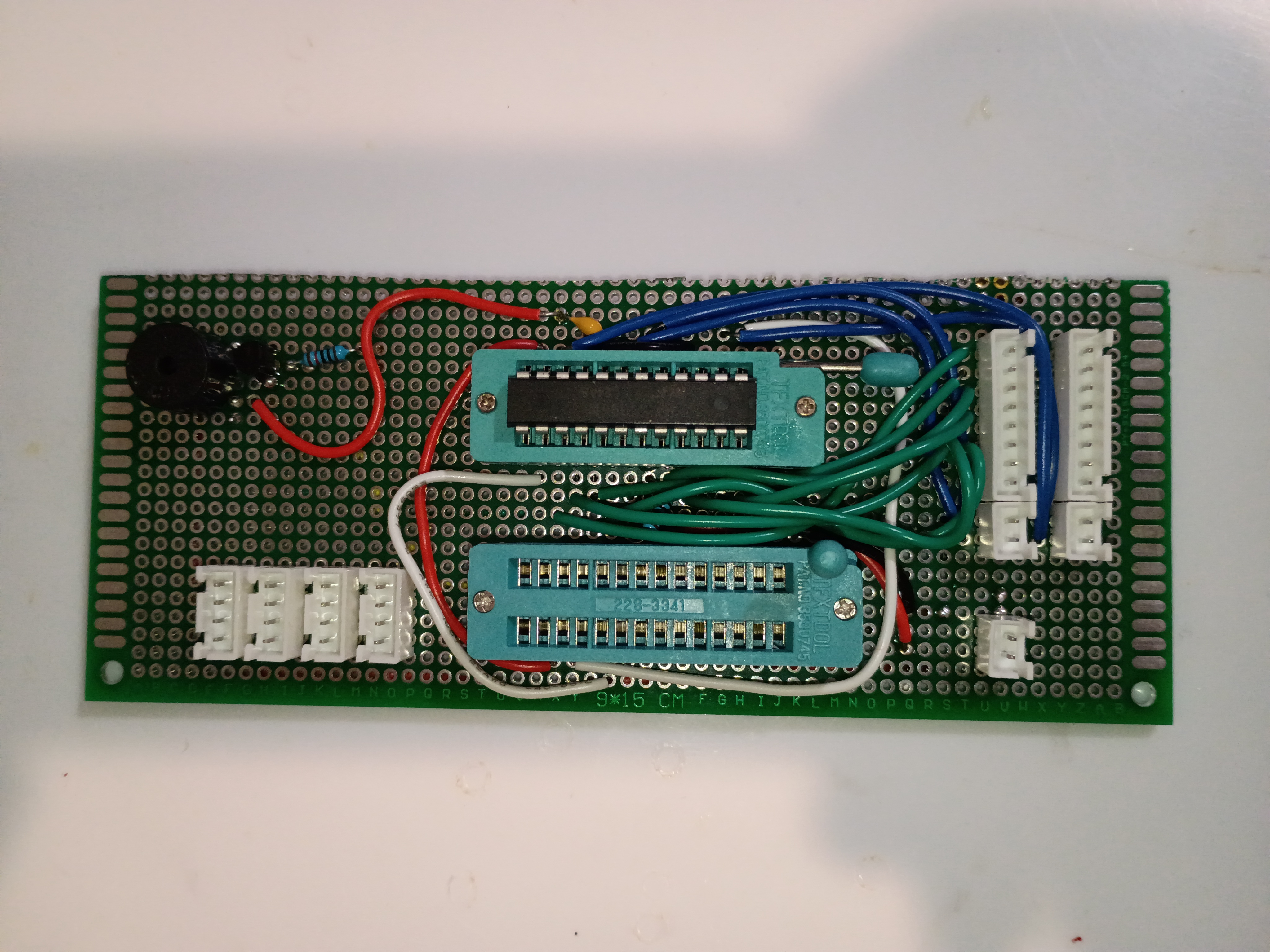
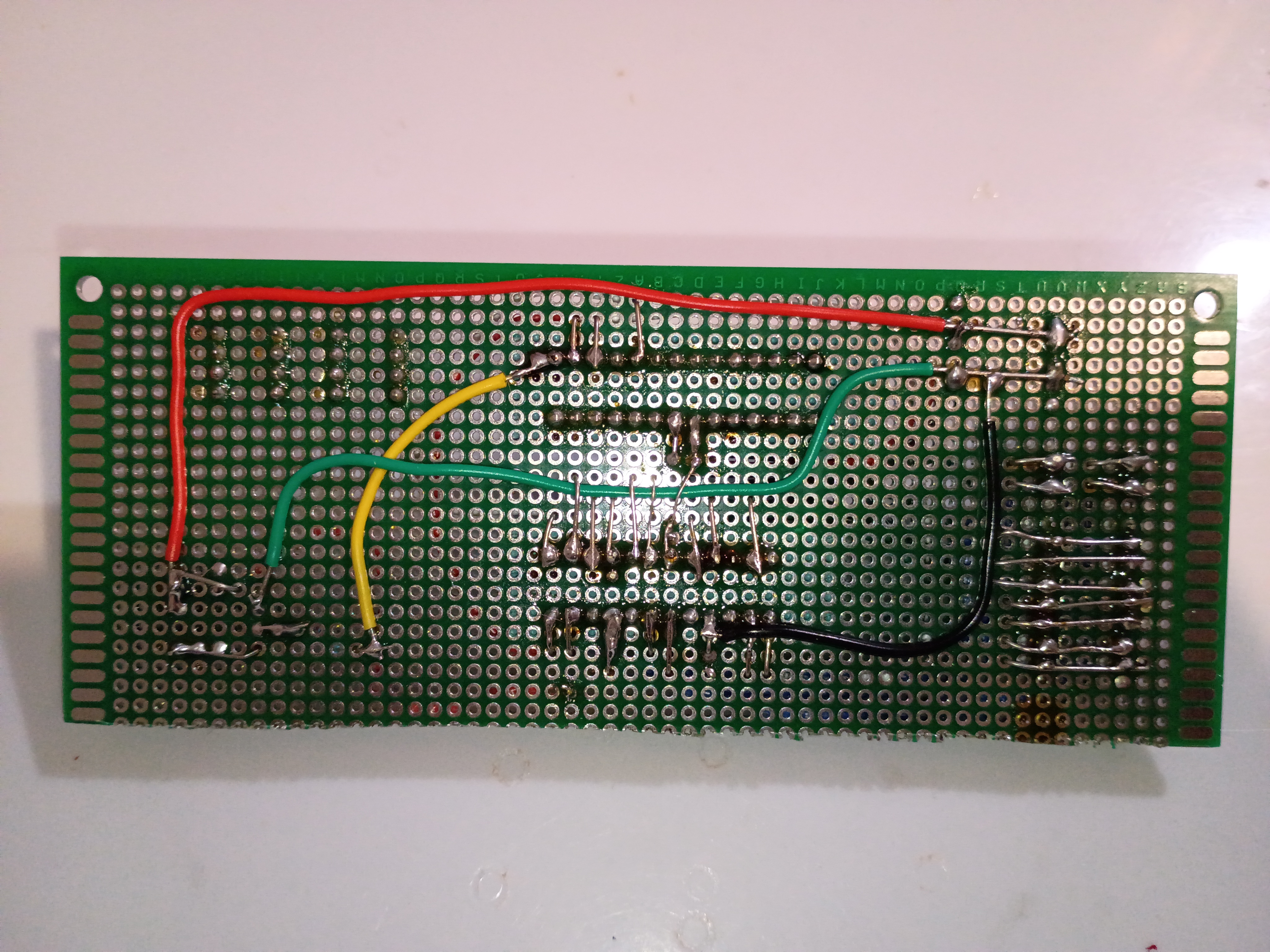
Cut perfboard with hacksaw and soldered several components. 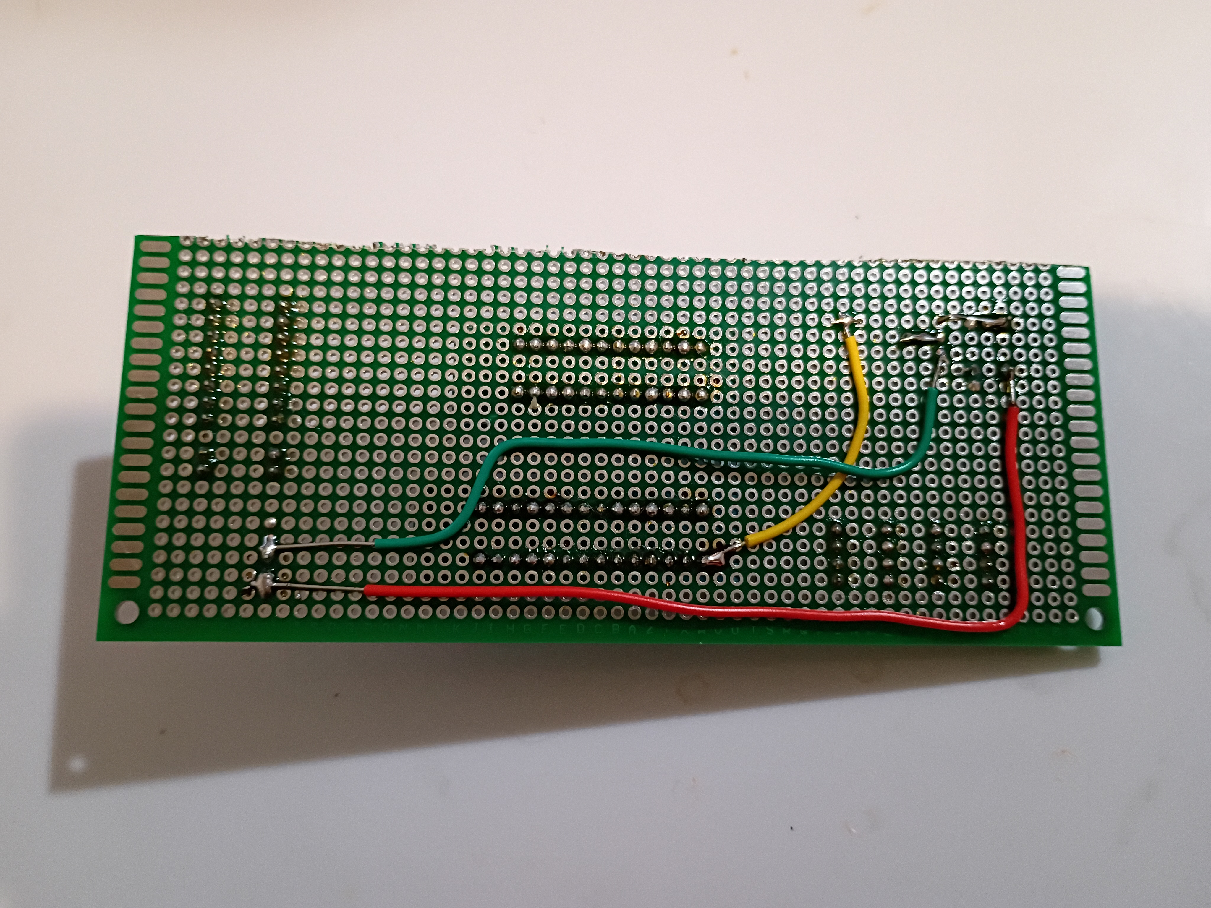
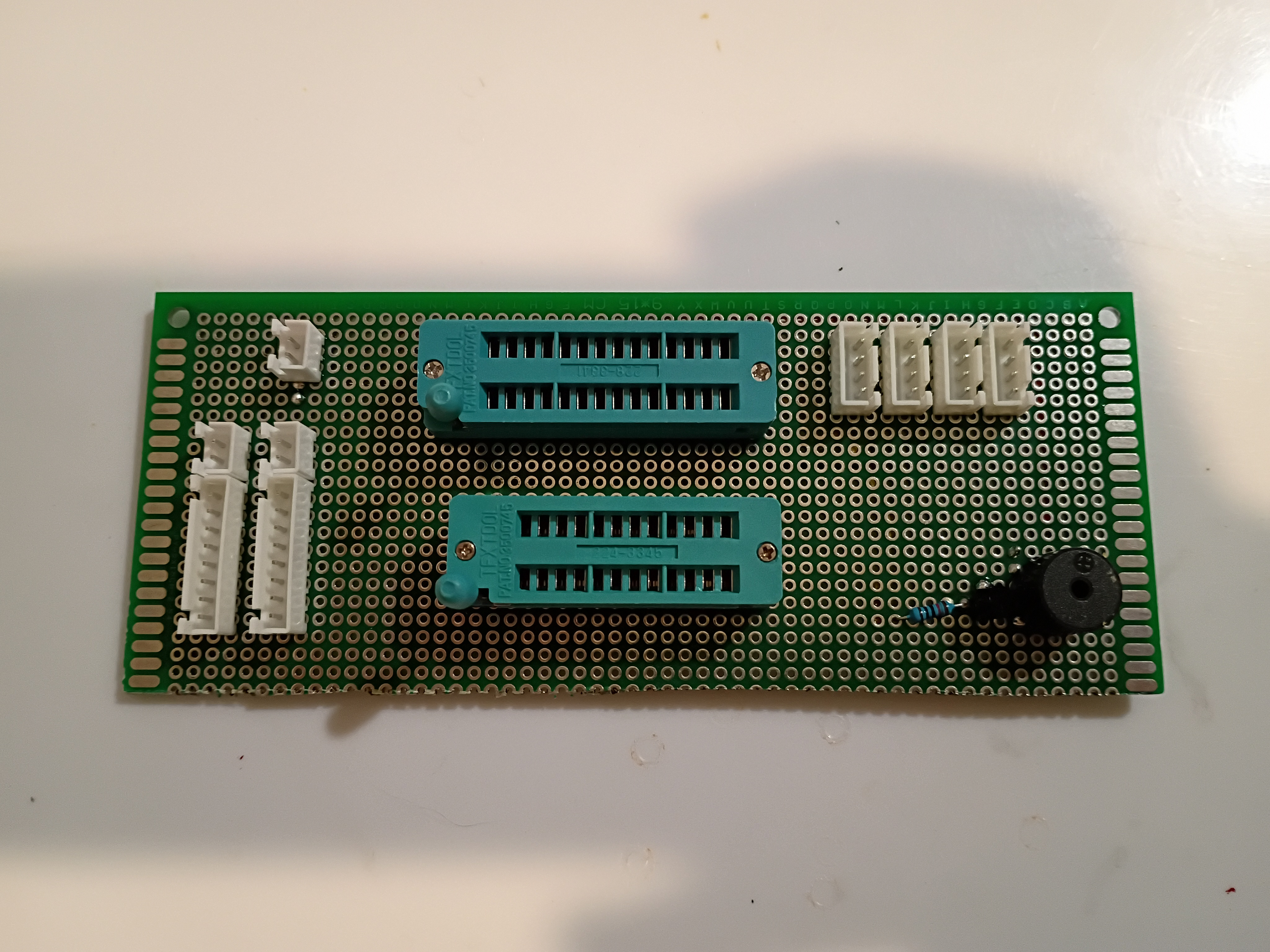
Got buzzer jingles and random integers working on Atmega328P using this C code to scare my cat.
Printed additional mounting components and installed M3x4x5 heat-set inserts. One trick is to set them 75% in and then flip the part over and press it into the table; that gives the best surface finish. Installed reed switches and central chassis onto underside of box surface. Installed small magnet into plastic block for testing purposes only. 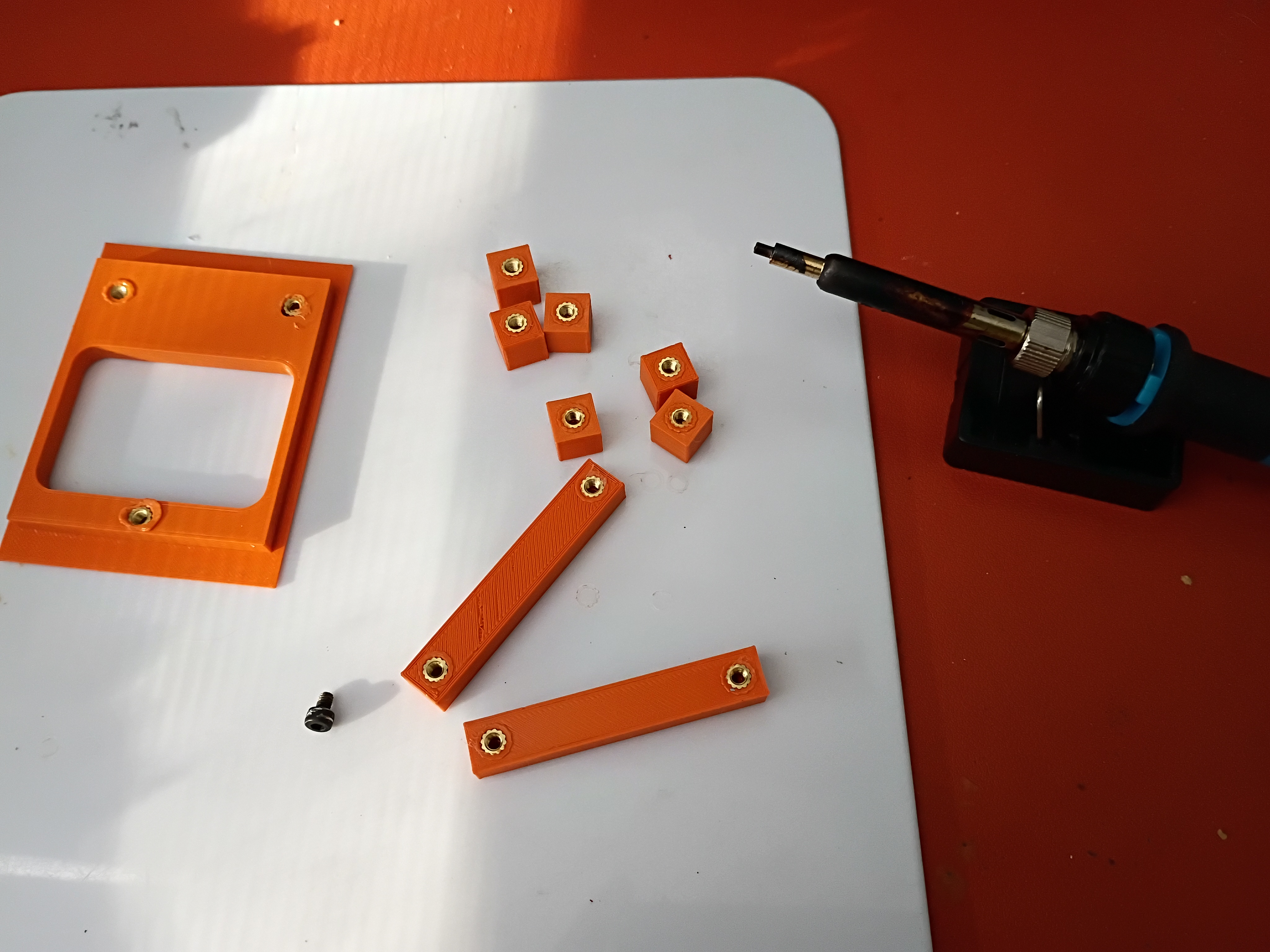
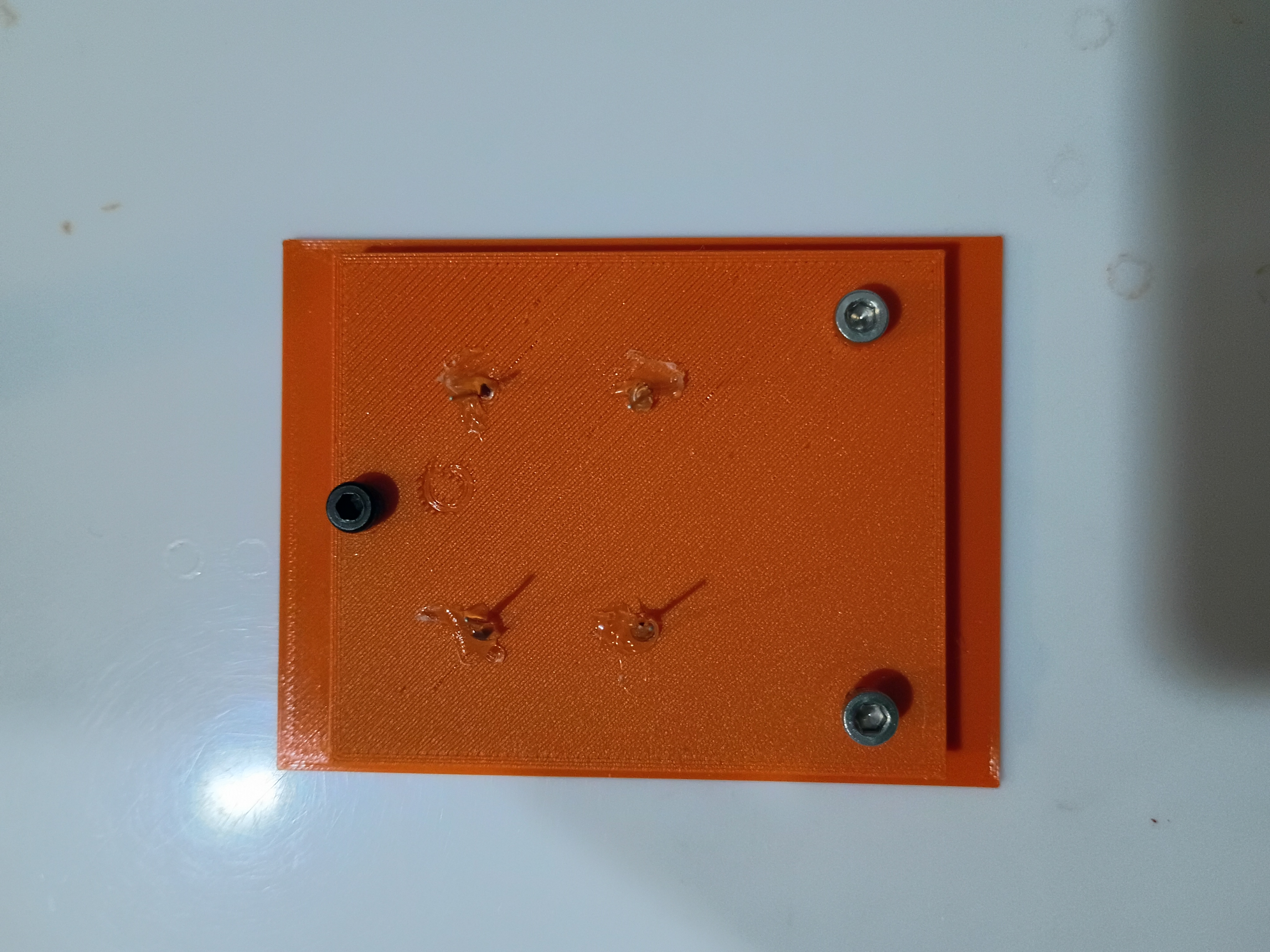
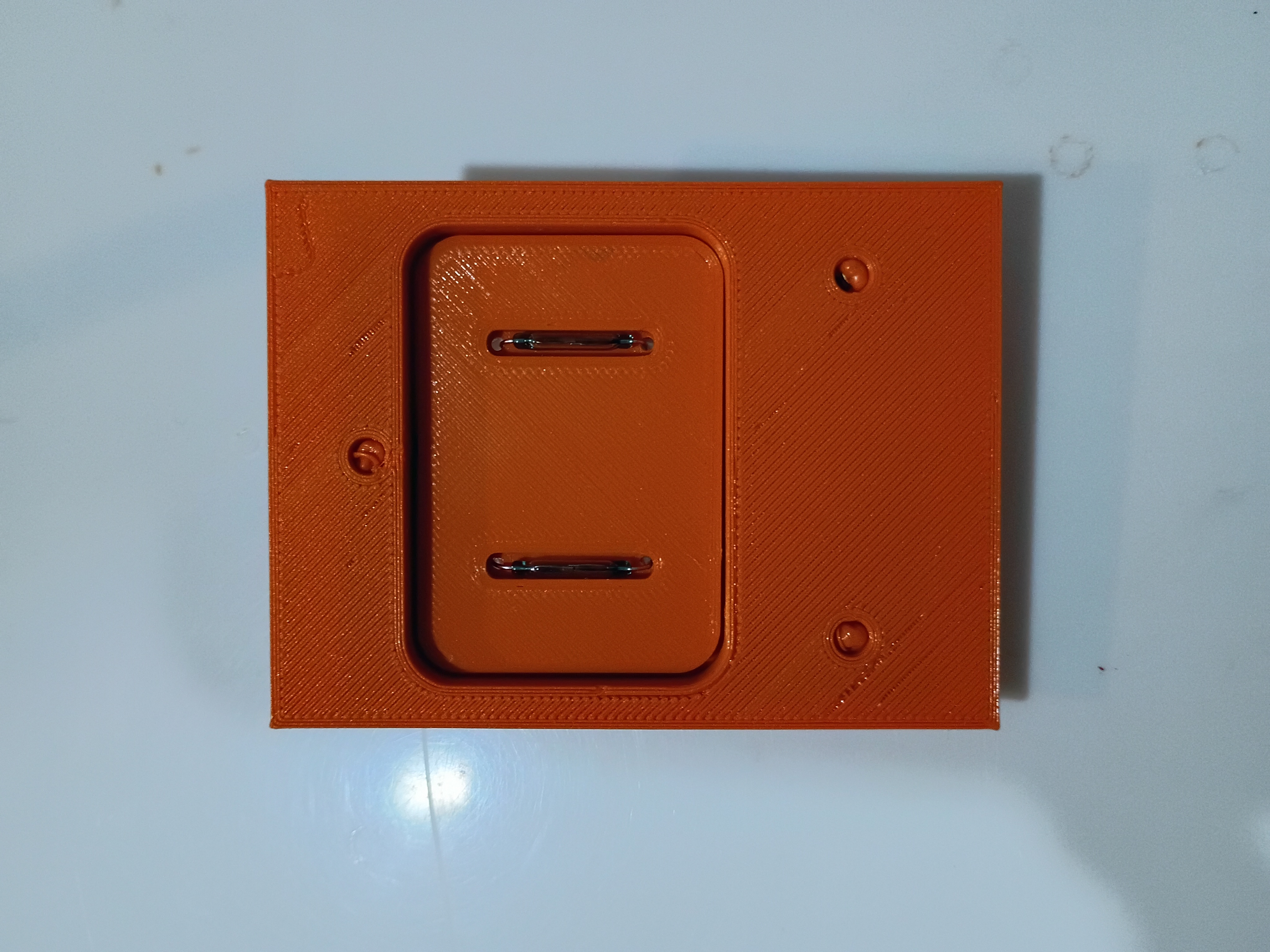
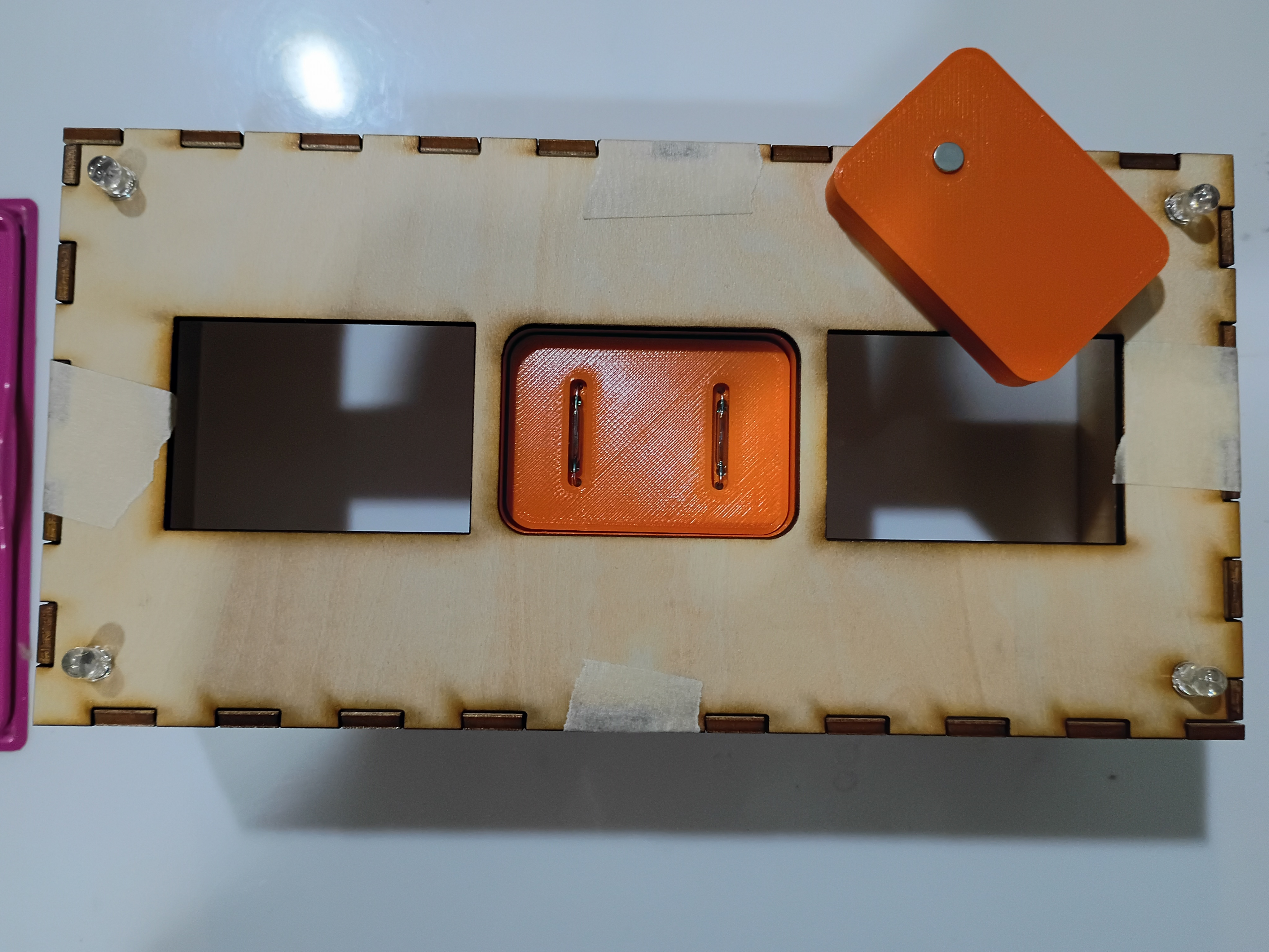
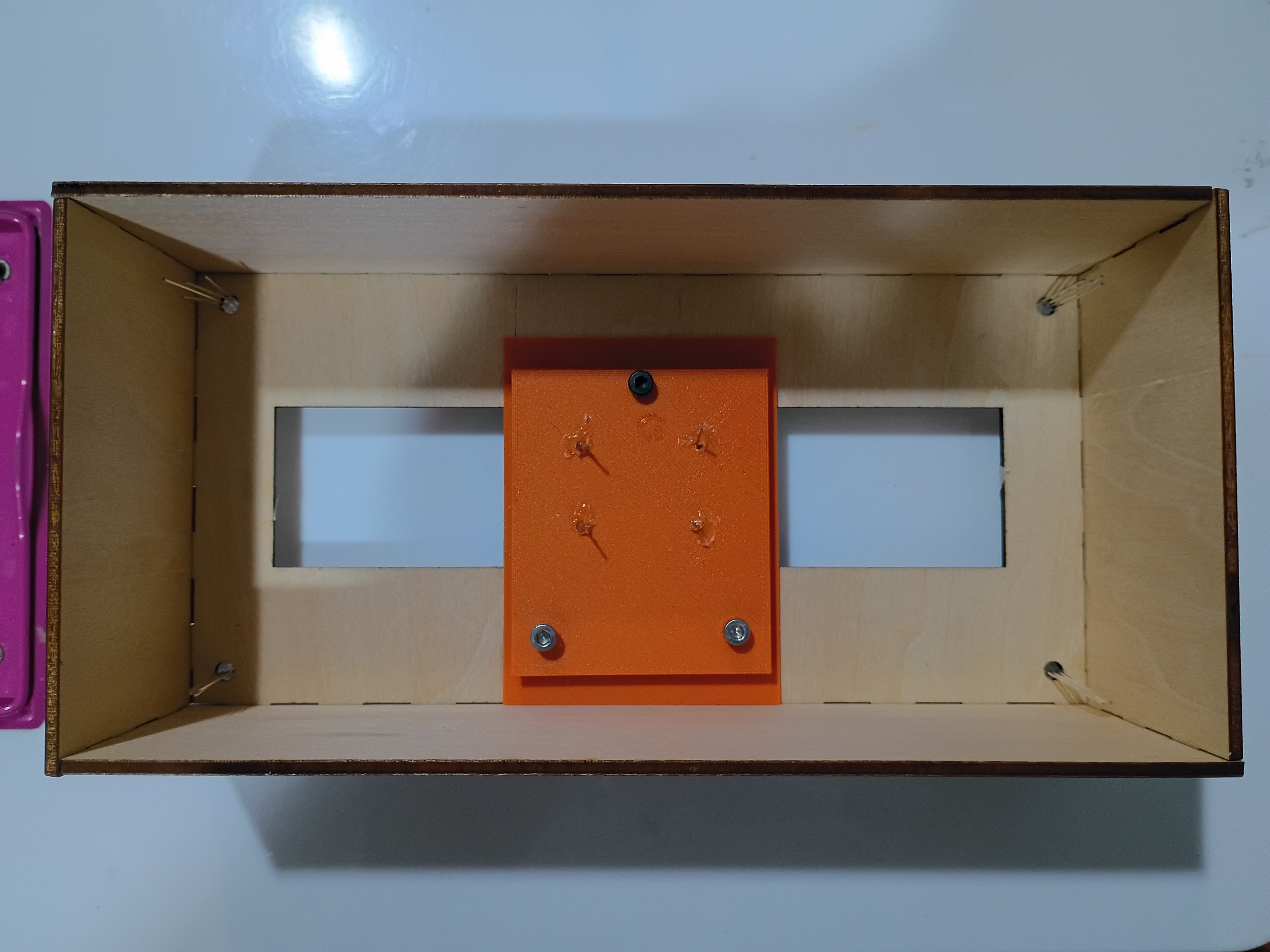
Continued to model assembly and began printing mounting components. 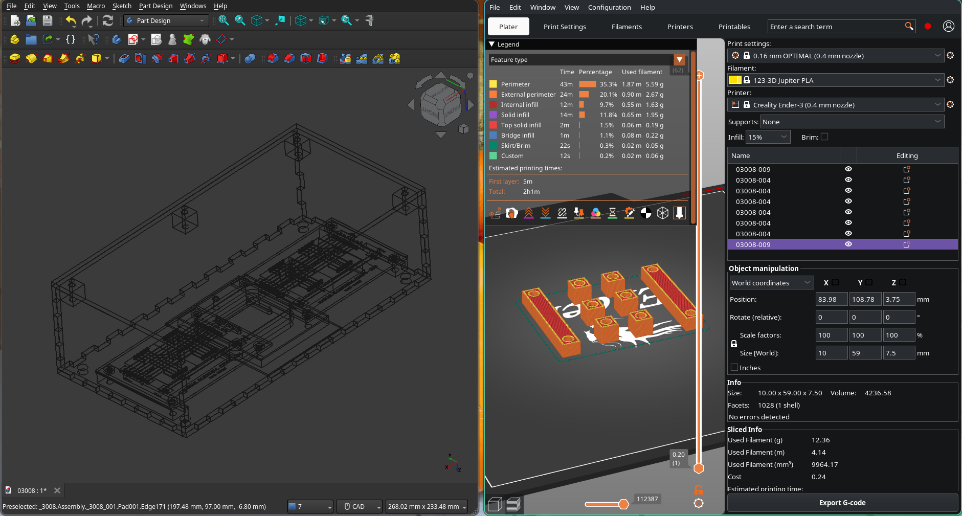
Mocked up removable reed switch holder and partial PCB support assembly. 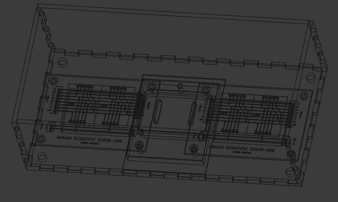
Several plywood panels were laser cut. 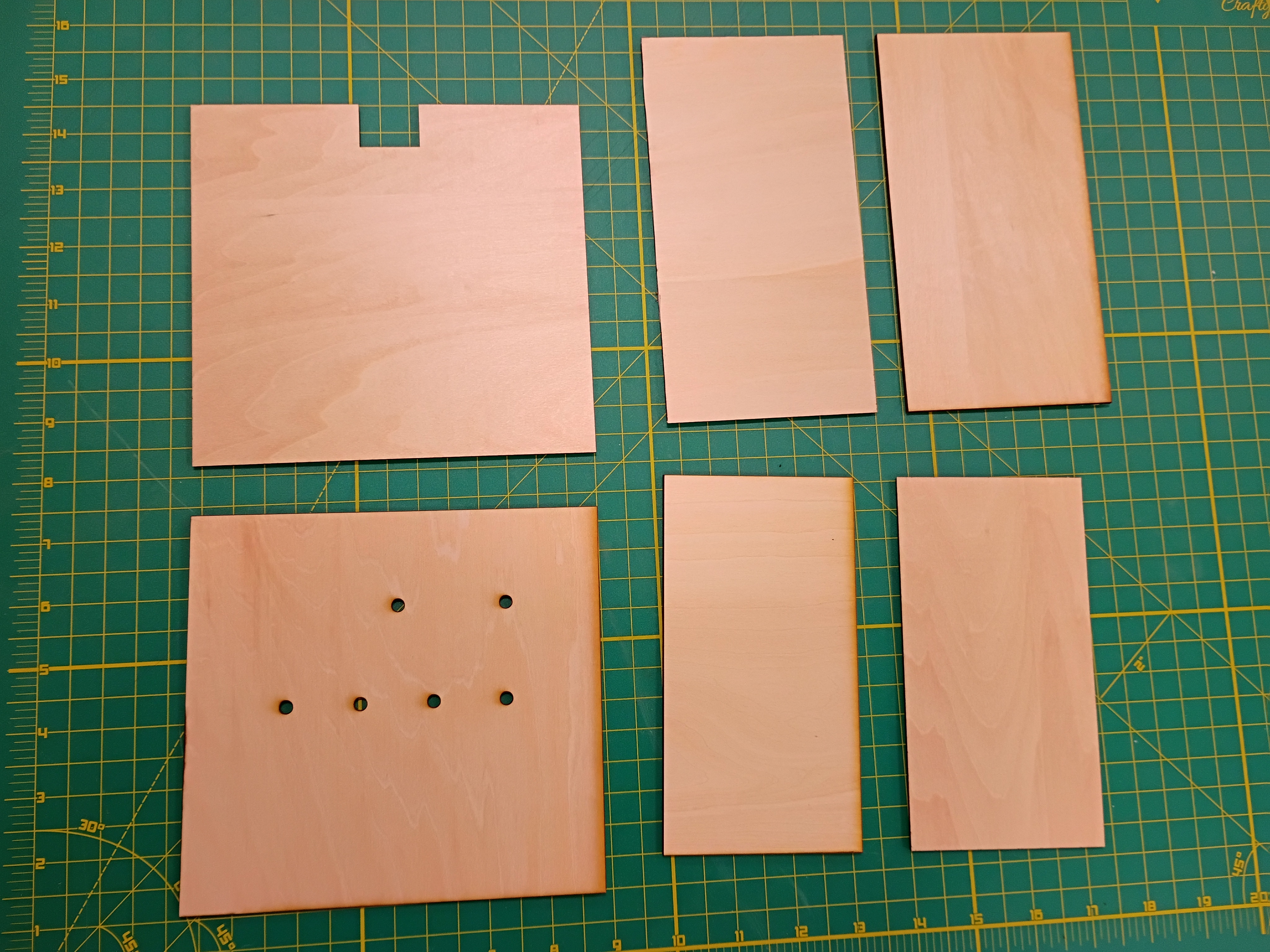
Designed (KiCad) and ordered PCBs (DKRed) to break out sets of 2x 7-segment displays to JST connectors. Cost per board was 11 dollars shipped, made in USA, to arrive in 10 days. Price seems mostly to do with board size. Decided not to expedite the shipping. 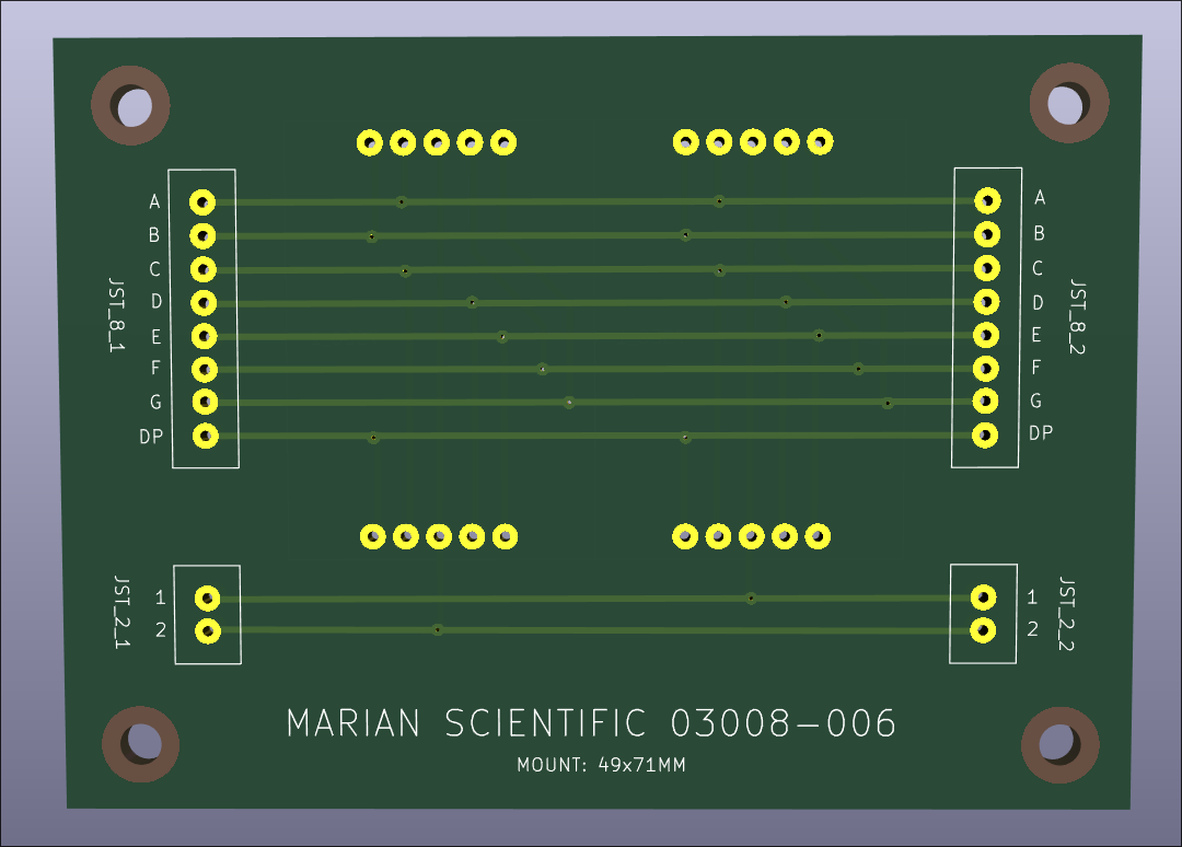
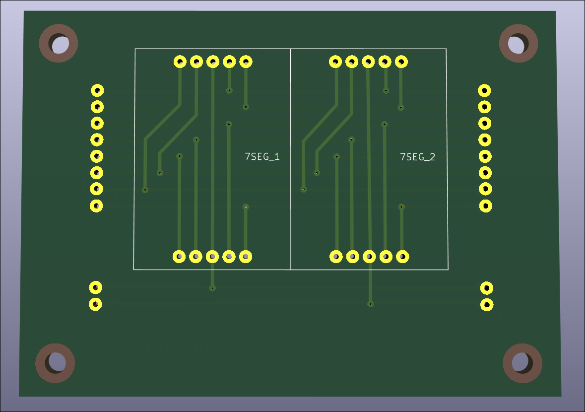
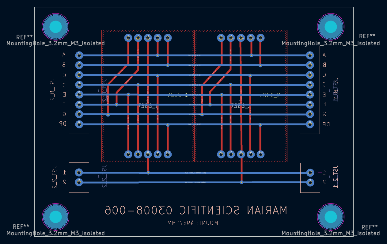
I conducted a preliminary fitment test of most of the electronic components in the box. I determined that getting small custom PCBs produced will drastically simplify the wiring and keep the box contents neat and robust. 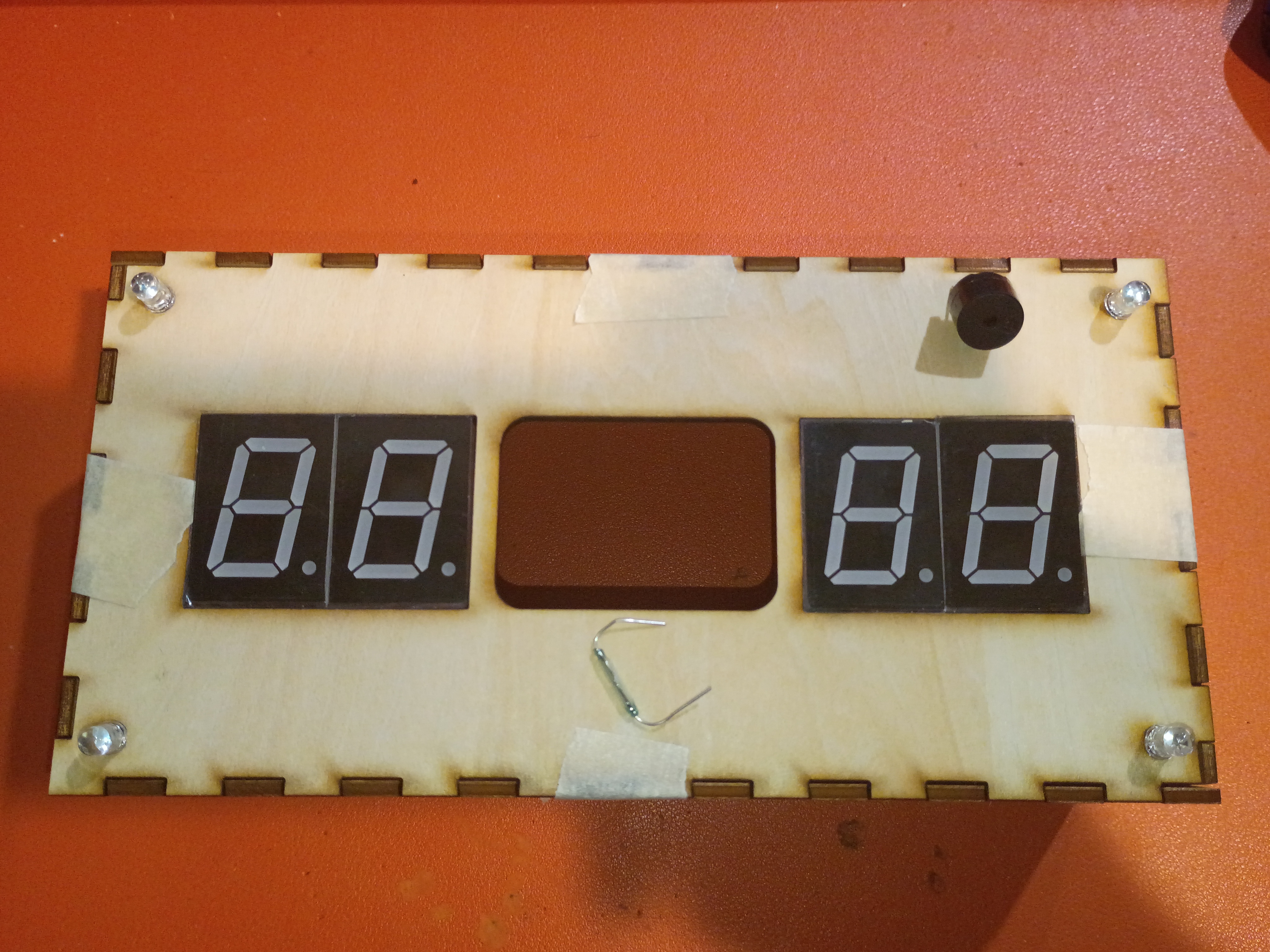
Laser cut around 30 finger-spacers. 20% power 20% current are decent settings for engraving the surface of plywood. Customer was satisfied. 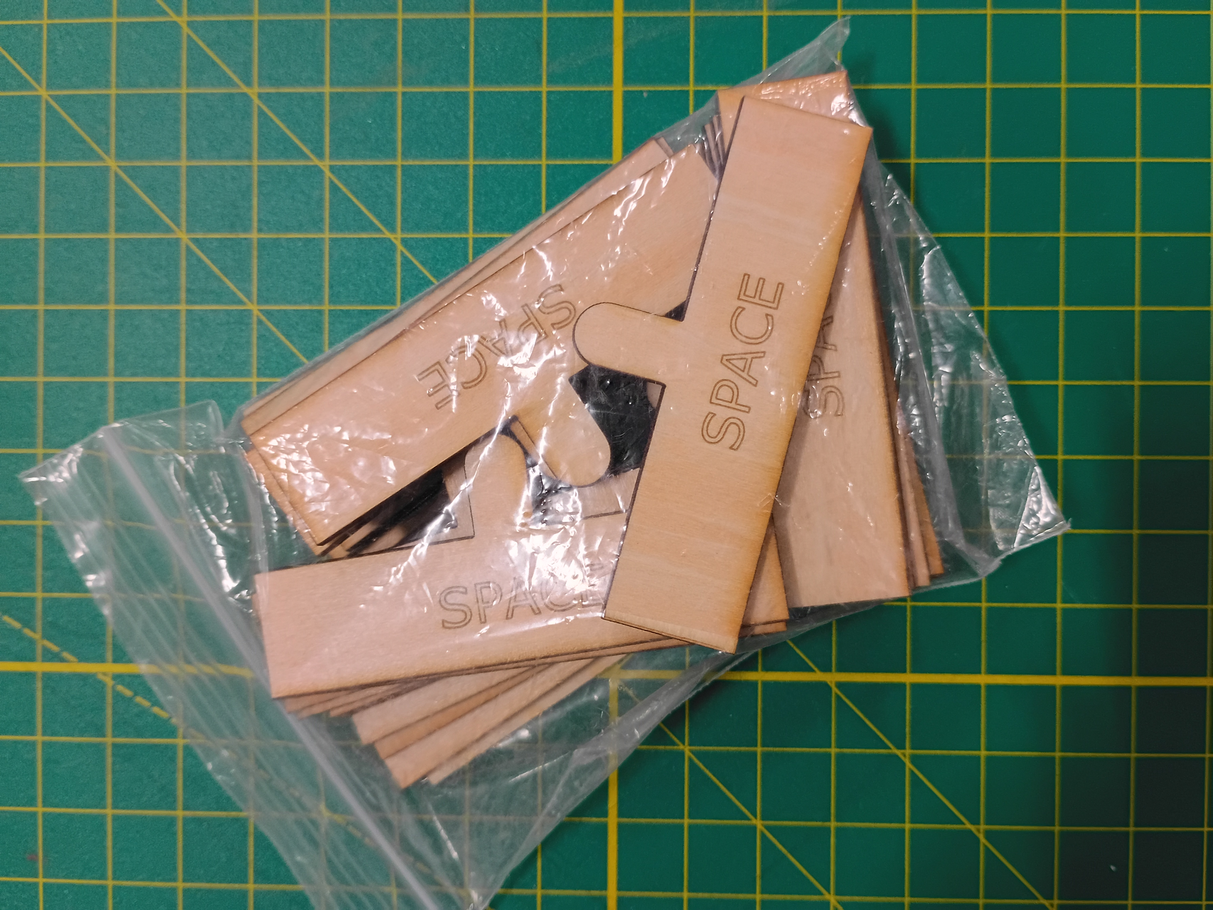
Most of draft box laser cut from 1/8-inch plywood with 3x10mm rectangular jagged edges. 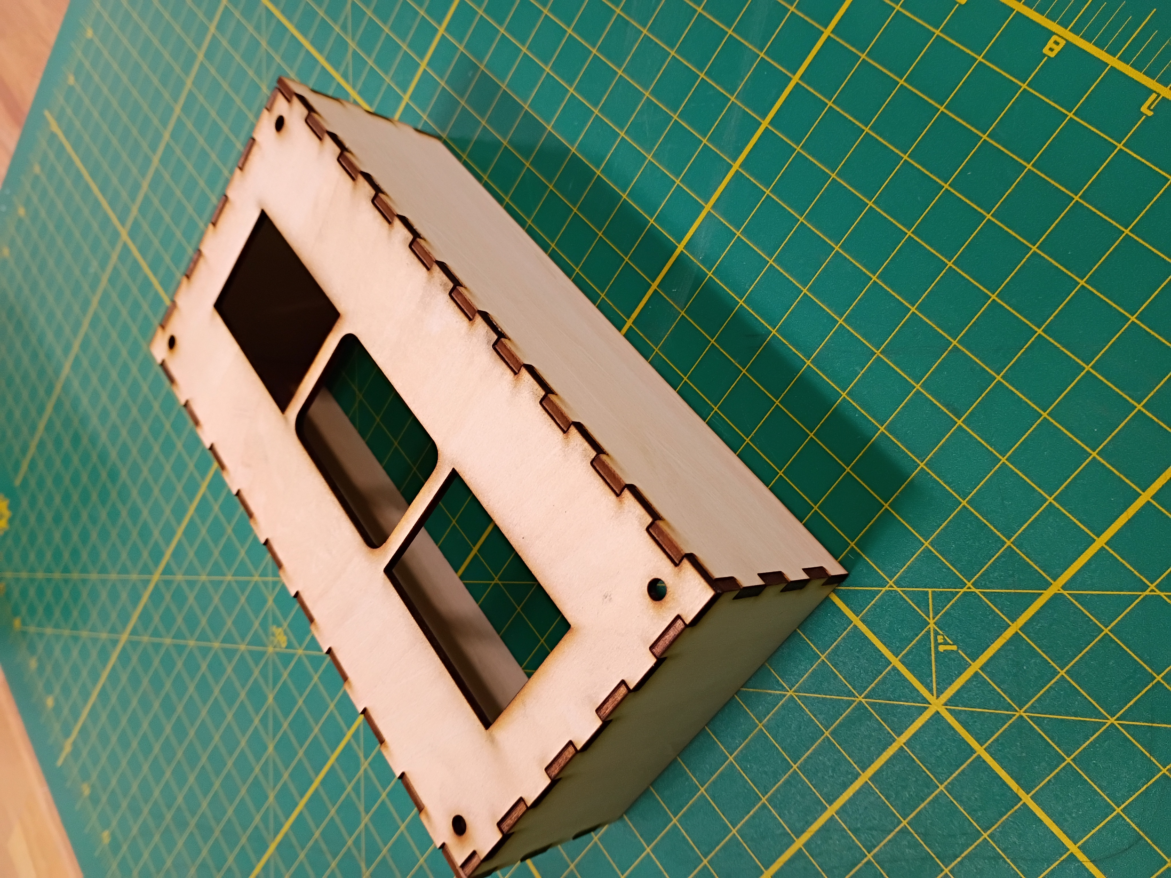
I wrapped up the 3D and laser cut definition for the box sides. 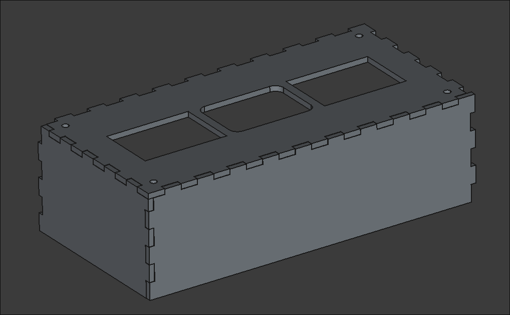
Created an SVG path for a finger-spacer tool to be laser cut. It helps children leave a space between words when they write. 
I mocked up a preliminary faceplate SVG to be laser cut. It has holes for the 7-segments, RGB LEDs & central block. 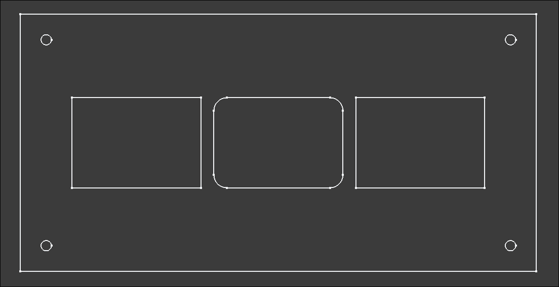
I also tested a USB-C power supply and a Reed switch as an alternative to the Hall effect sensor. It is extremely sensitive.
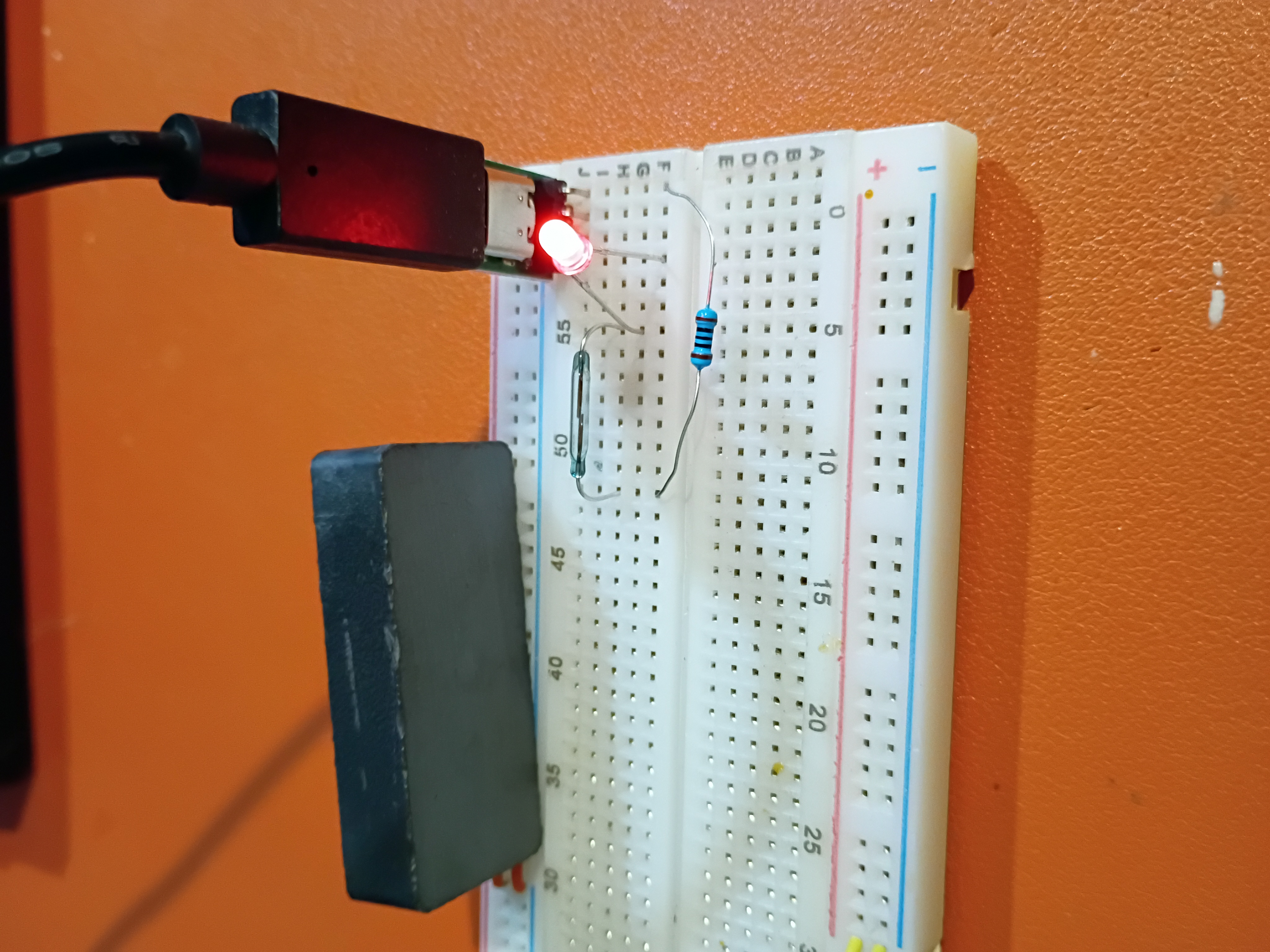
I updated the GitHub workflow and script to automatically create thumbnail images and added a shorthand for embedding & linking them, among other website formatting improvements.
I adapted the Atmega328P C code to control the 4x separate 7-segment displays.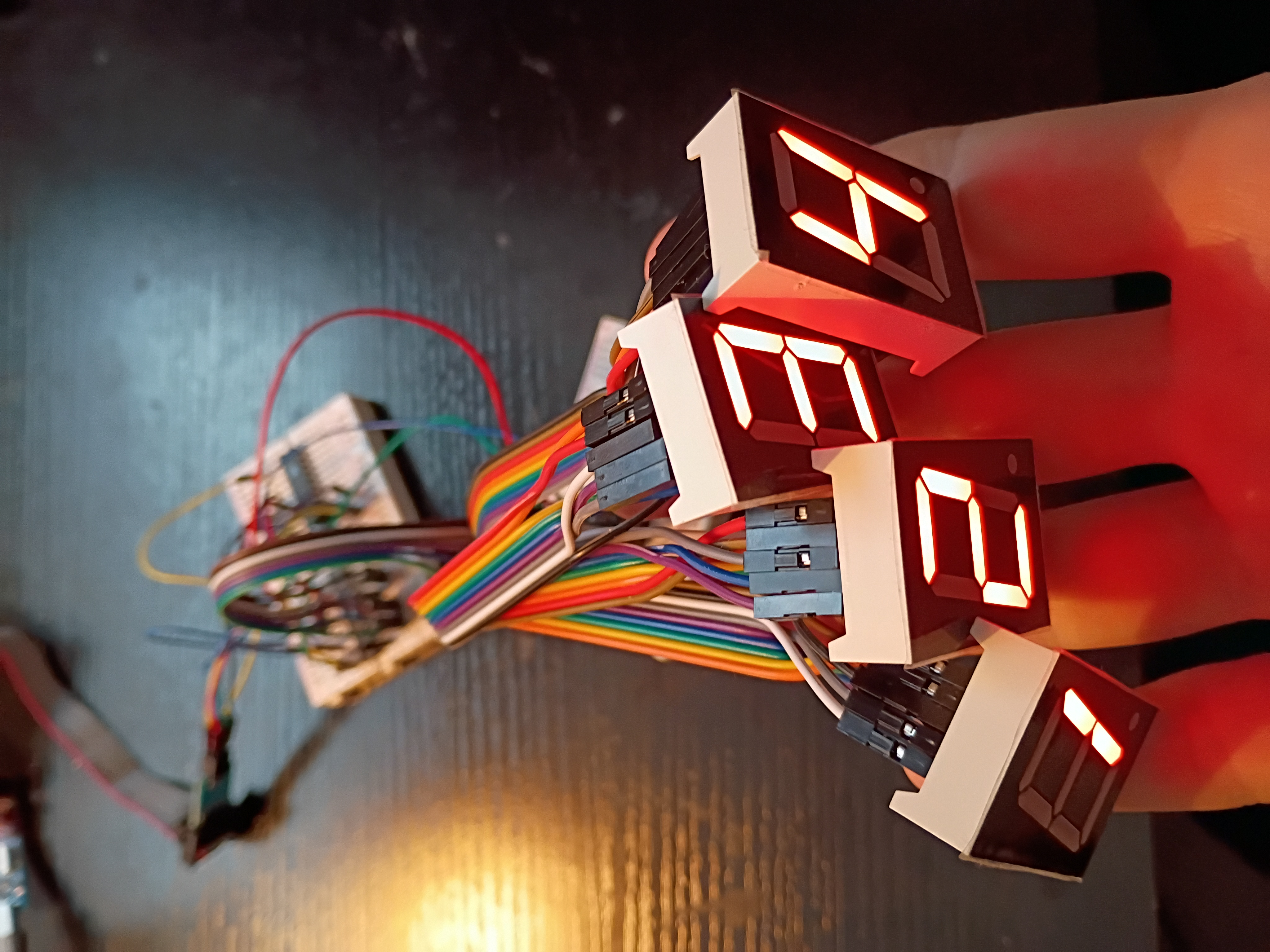
I hooked up 4x 7-segment displays to the MAX7219 IC for testing tomorrow.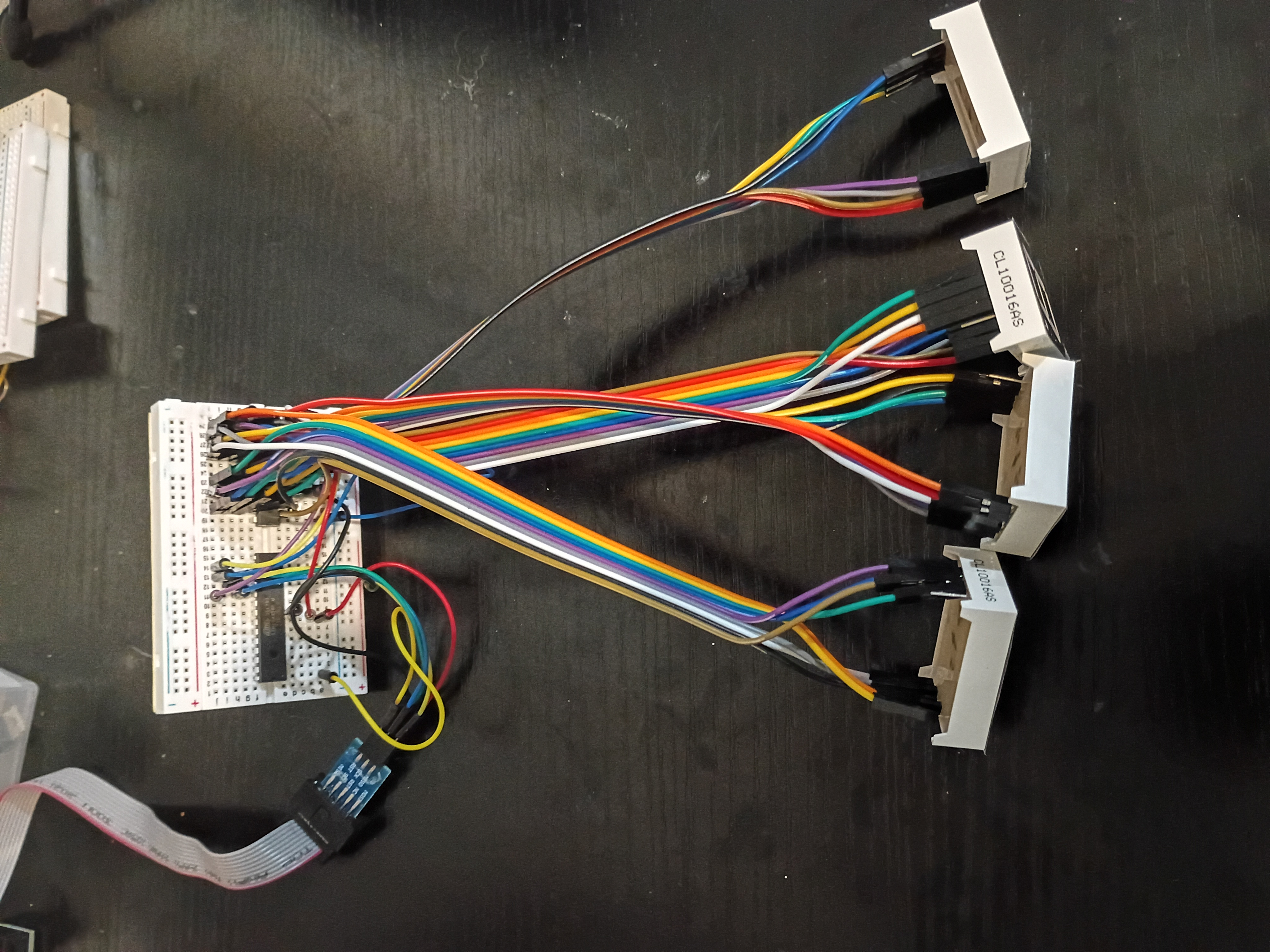
After much debugging (2 days), I realized I had the Rset resistor on the MAX7219 jumping to GND instead of 5V. I thought for sure it was supposed to go to GND. Either way, we have this Atmega328P C code to control a 7-segment display over what is essentially SPI.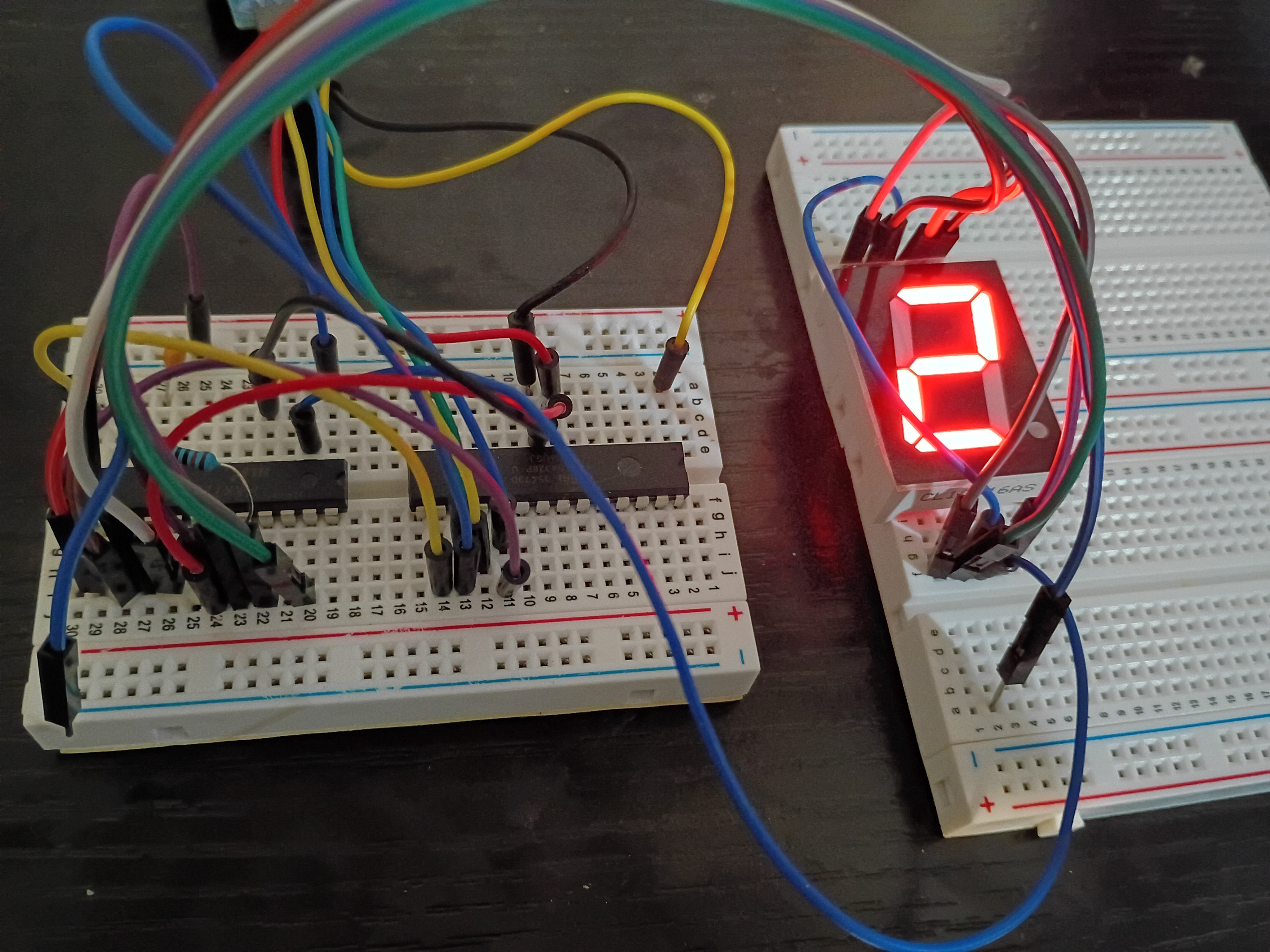
Got some exposure to laser cutting on the Muse3D at work. Made some personal engravings and tested various power setting and cut speeds. At 100% power even 100% speed is enough to cut thru 1/8-inch plywood.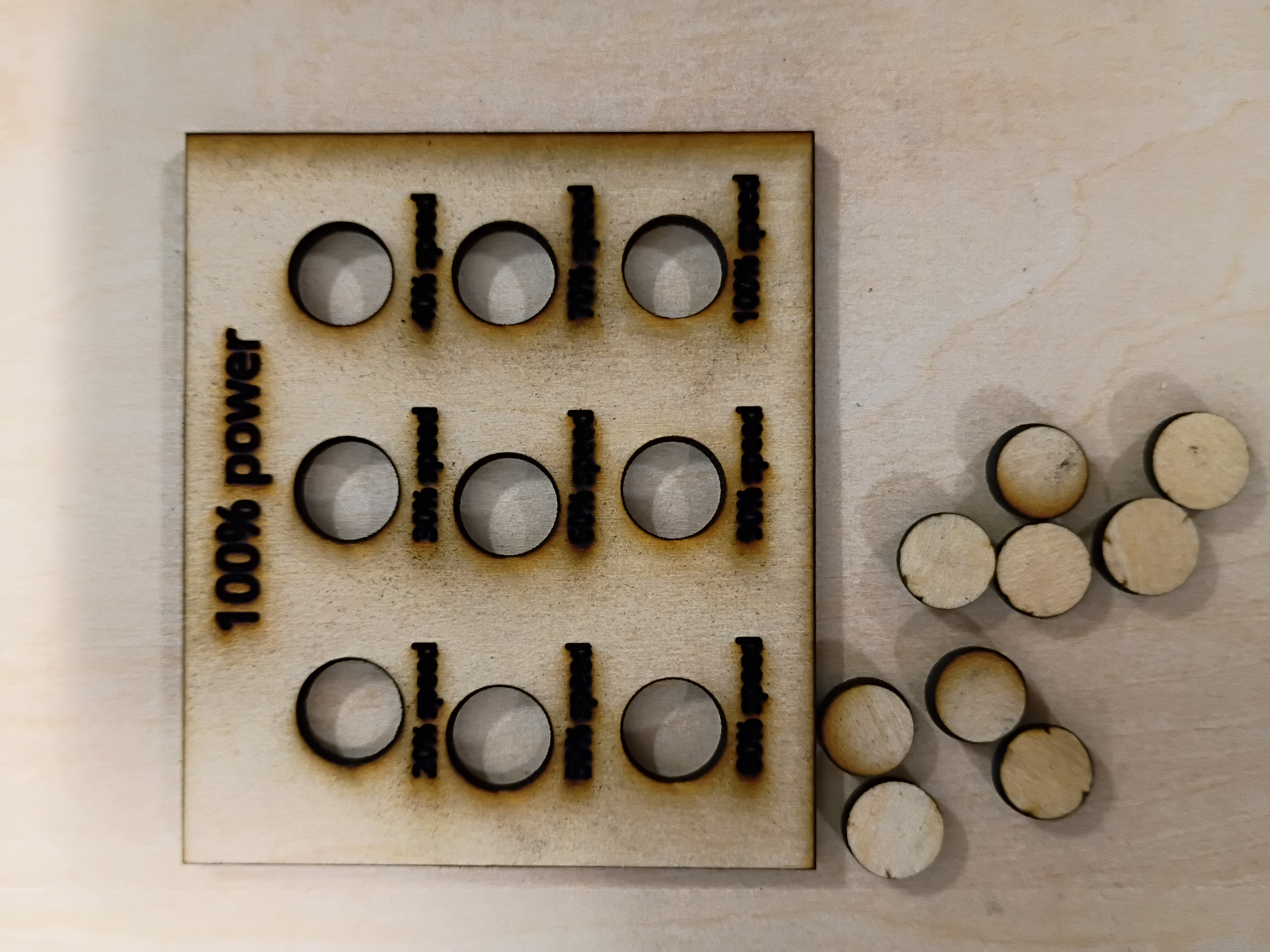
I set up an automated GitHub workflow to generate these journal entry pages automatically and updated the construction script to handle an index page. More to come.
I attempted to implement a circuit to control a 7-segment display using the MAX7219 driver IC, but unfortunately my 7-segment displays are all common-anode, so they are not trivially compatible. While I source common-cathode ones, I tested a basic digit Hall-effect circuit using an LED.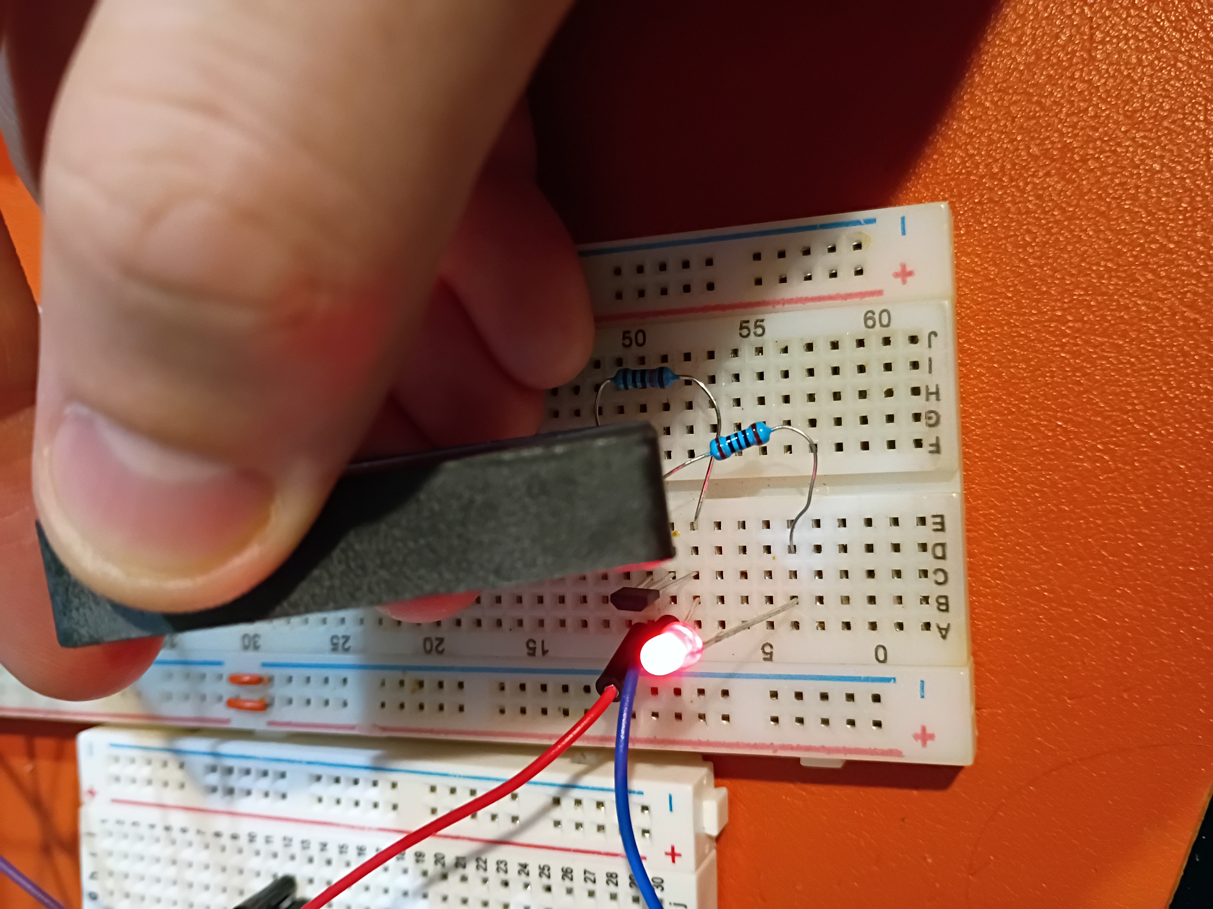
I tested control of an RGB LED with an Atmega328P here.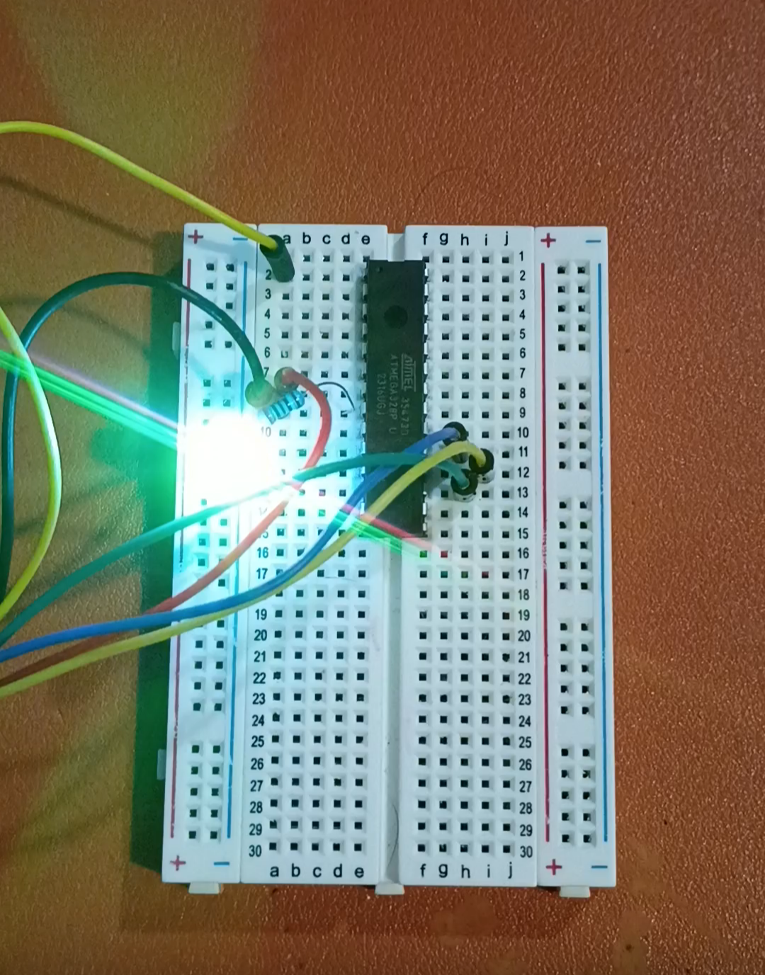
In response to RFP004 - MM1, two candidate 'microcontroller experiences' were proposed in submission xMM1.