Wrote the Readme page on the MS project repository. This contains a short description of MM1 Minute Hand and the challenges faced when developing the project. The description of the MCU program is attached to the Readme as well.
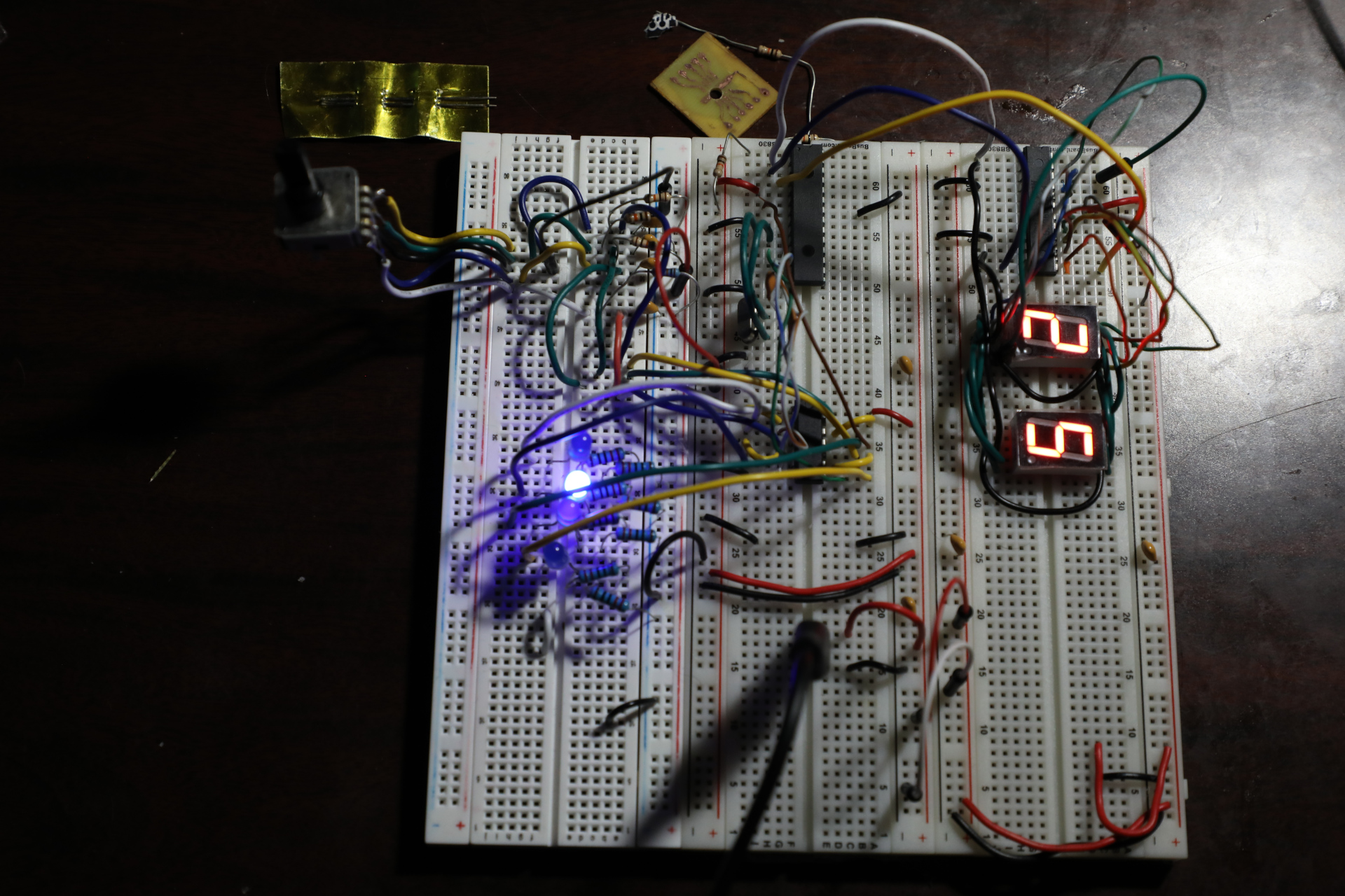
The rightmost breadboard was replaced and all of the components were replaced into another breadboard. The encoder section of the circuit (leftmost breadboard) had 10k resistors removed and the signals from the encoder had more fidelity. The encoder signals were routed to the 74LS00 (which acts as an isolation to the MCU and an inversion) and the output of those are connected to the Atmega328P. The Code was then updated and we have a visible reading from the seven segment displays. But not everything is working. The Segment displays do not output a live reading from the enocder very well.
Took a AI generated Company quiz on the Max7219 Datasheet found here: https://www.analog.com/media/en/technical-documentation/data-sheets/max7219-max7221.pd
Yesterday, I burned a bootloader on the atmega328P chip, which is now removed from the board shown below. 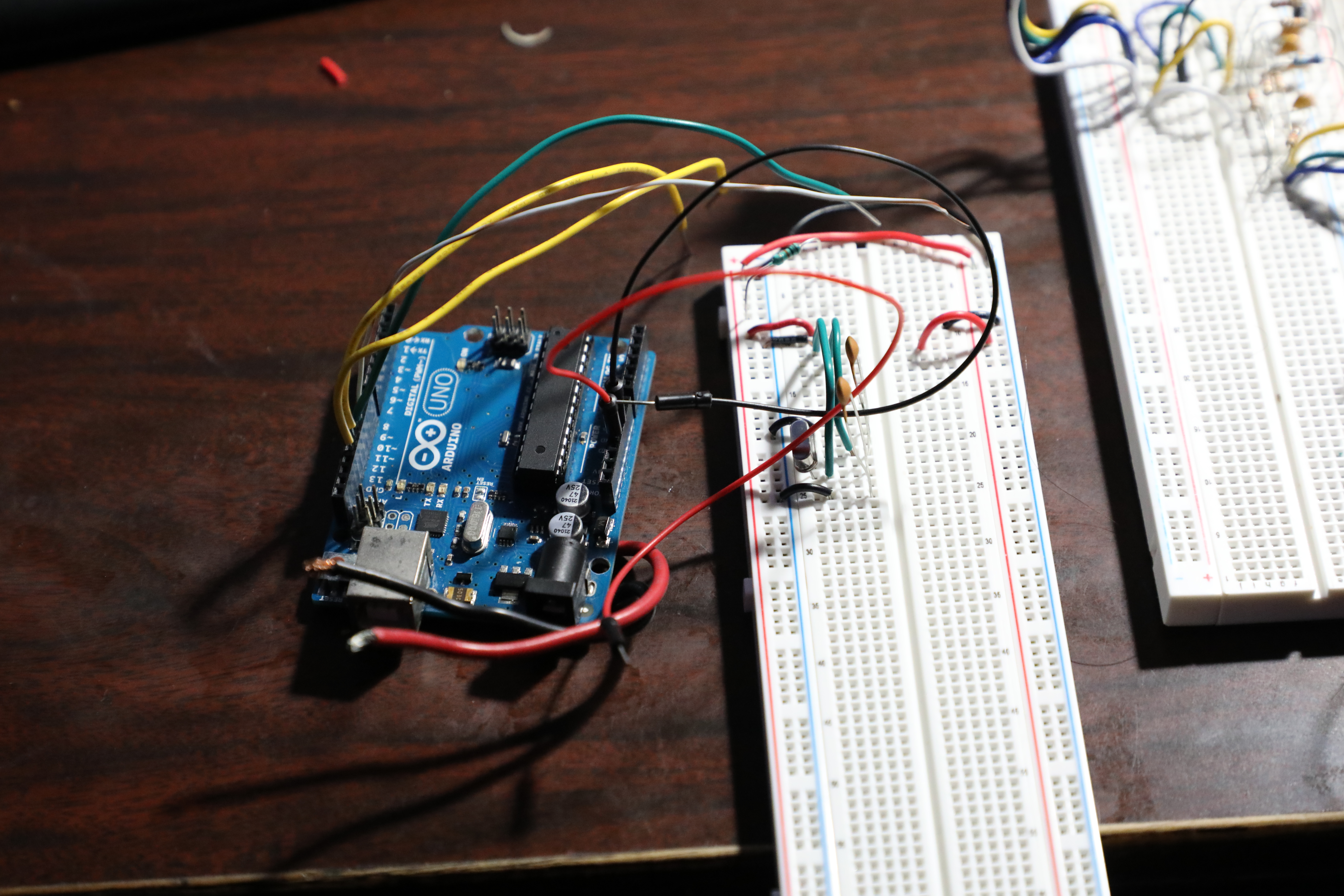
Yesterday, I programmed another stm32 bluepill and I added a Logic Leveler from 3.3V to 5V.
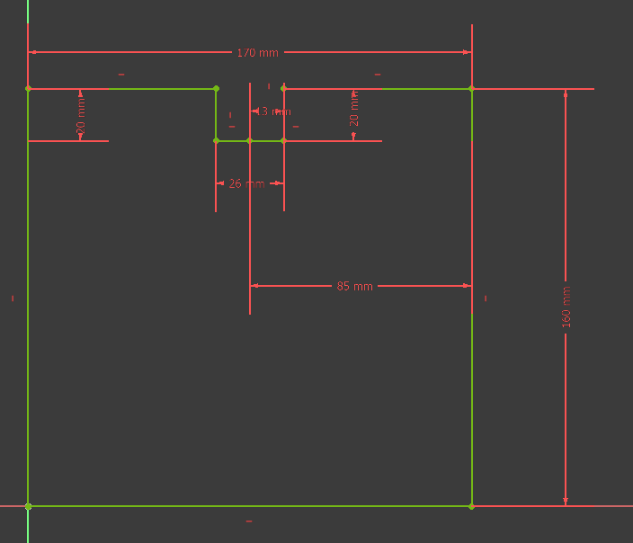
Yesterday, When the Mounted seven segment displays arrived, I realized I has a little problem. This is a front that was designed by myself for MM1 Minute hand.
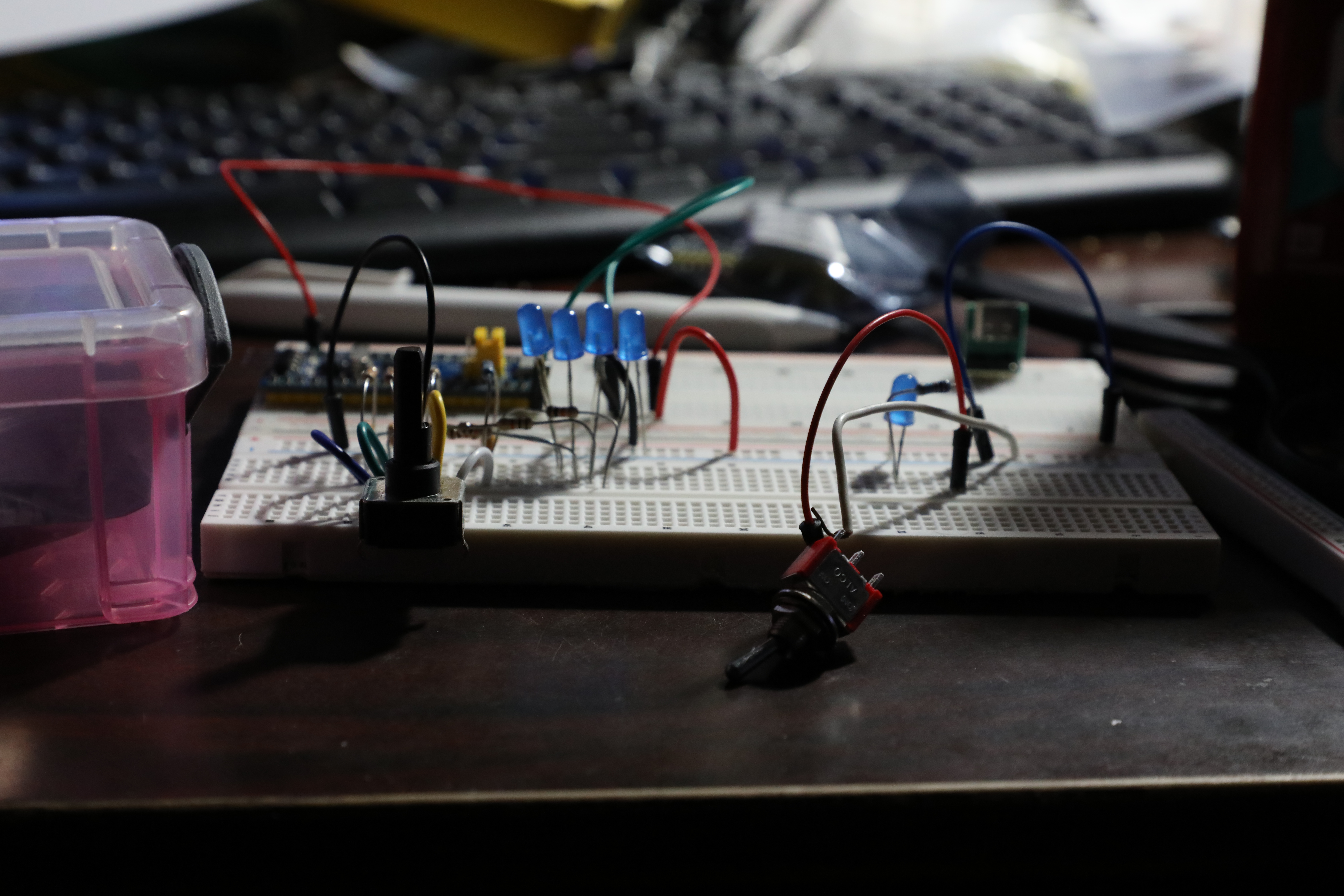
A few days ago, there was a lot of work done. The circuit was constructed on a breadboard. 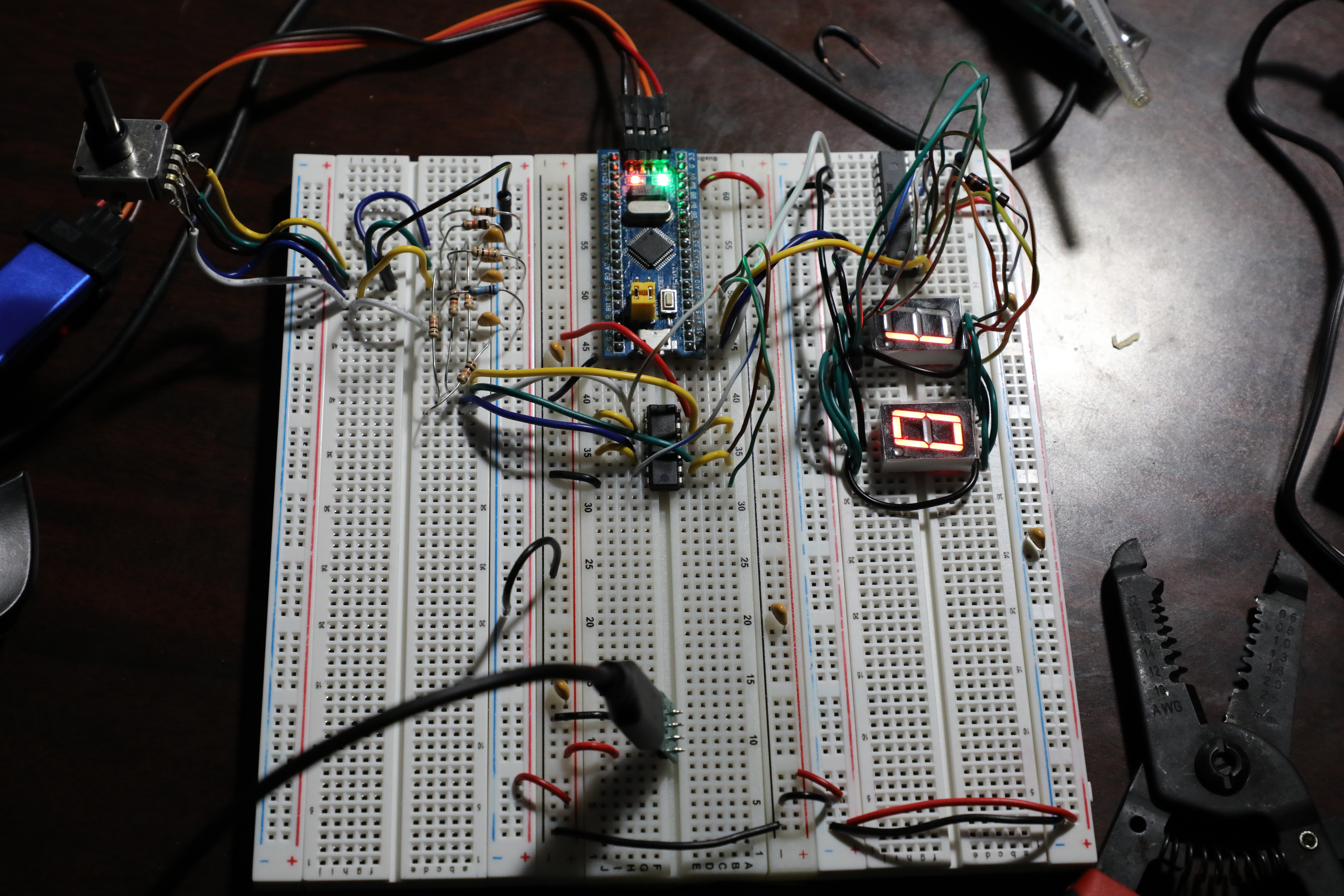
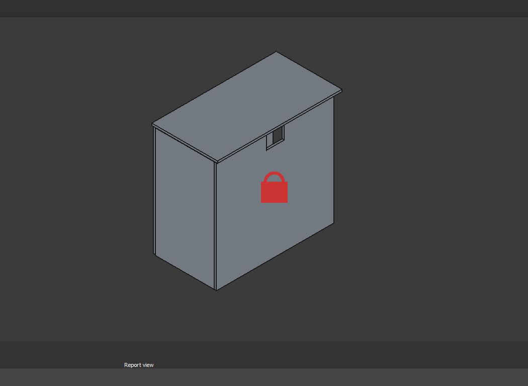
Here is an isometric view of 03009 MM1 Minute Hand with a 'cutoff' from the front panel.
Over the past several days, there was a major effort to complete the CAD for the MM1 Minute hand gears.
Printed several gear components. Manufacturing recommendation is to make the hole in the hour drive gear all the way thru the part and increase the inner diameter slightly (0.1mm) for better clearance with the minute shaft. Components were assembled and functionality was tested successfully. 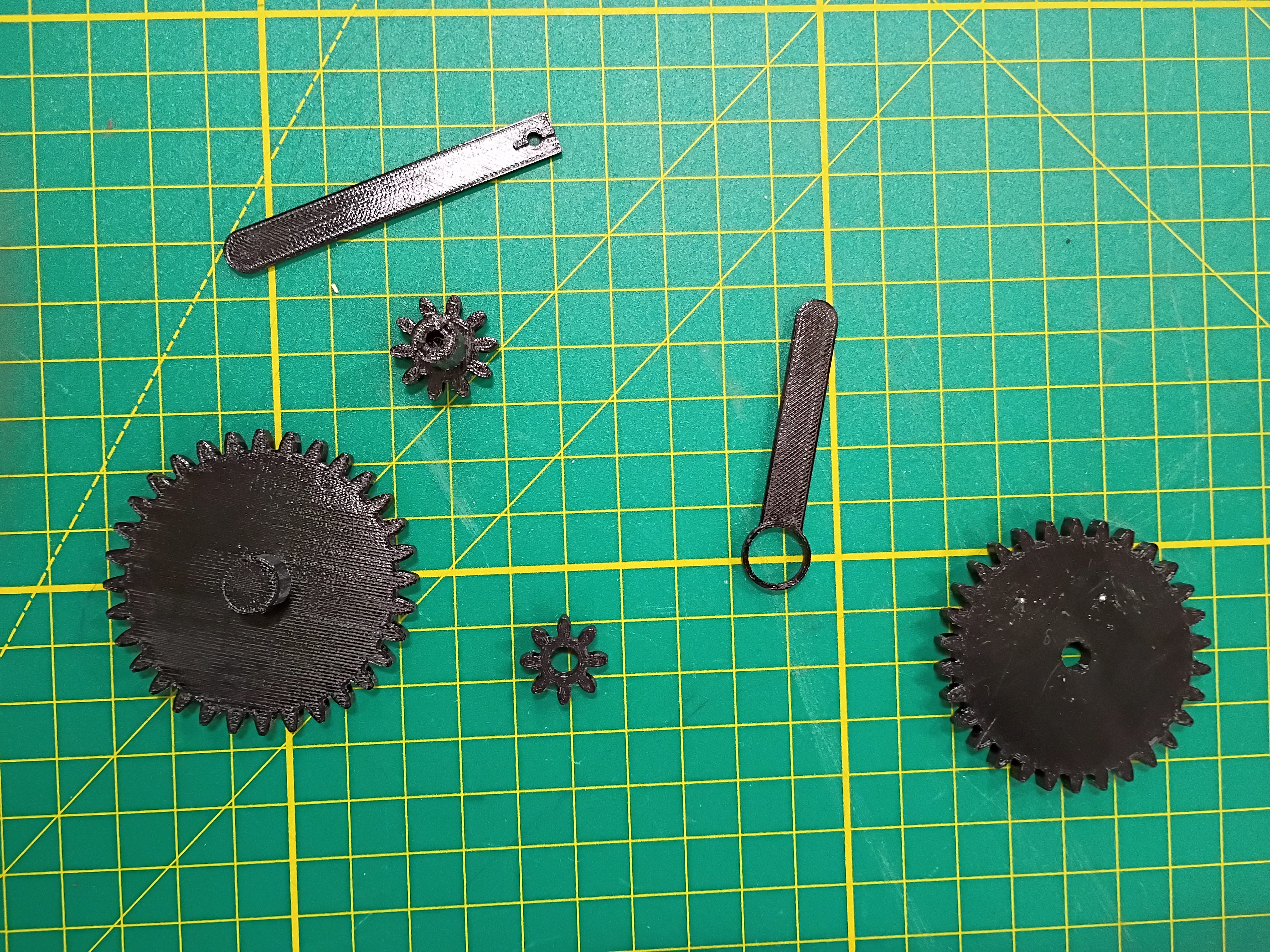
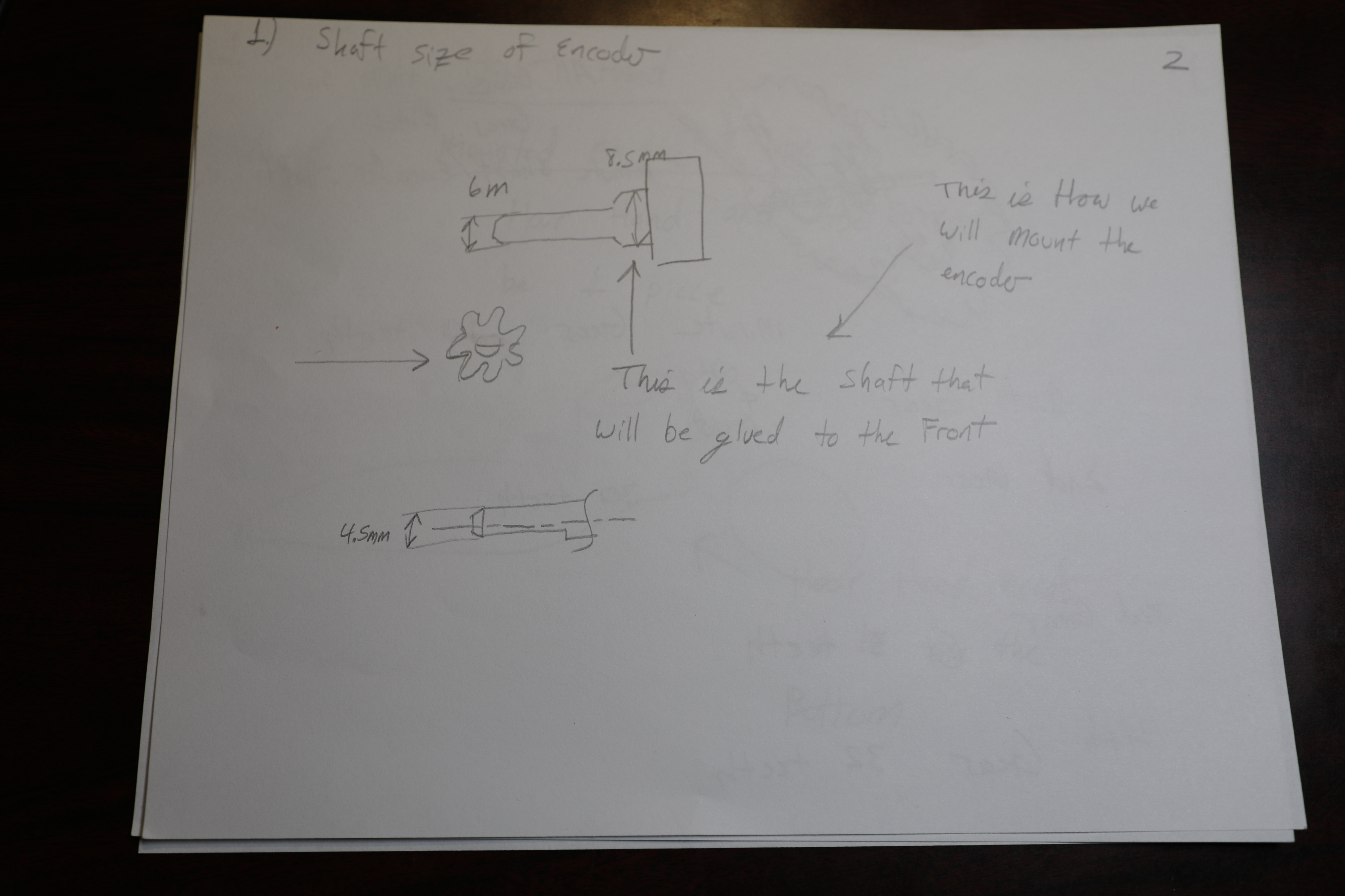
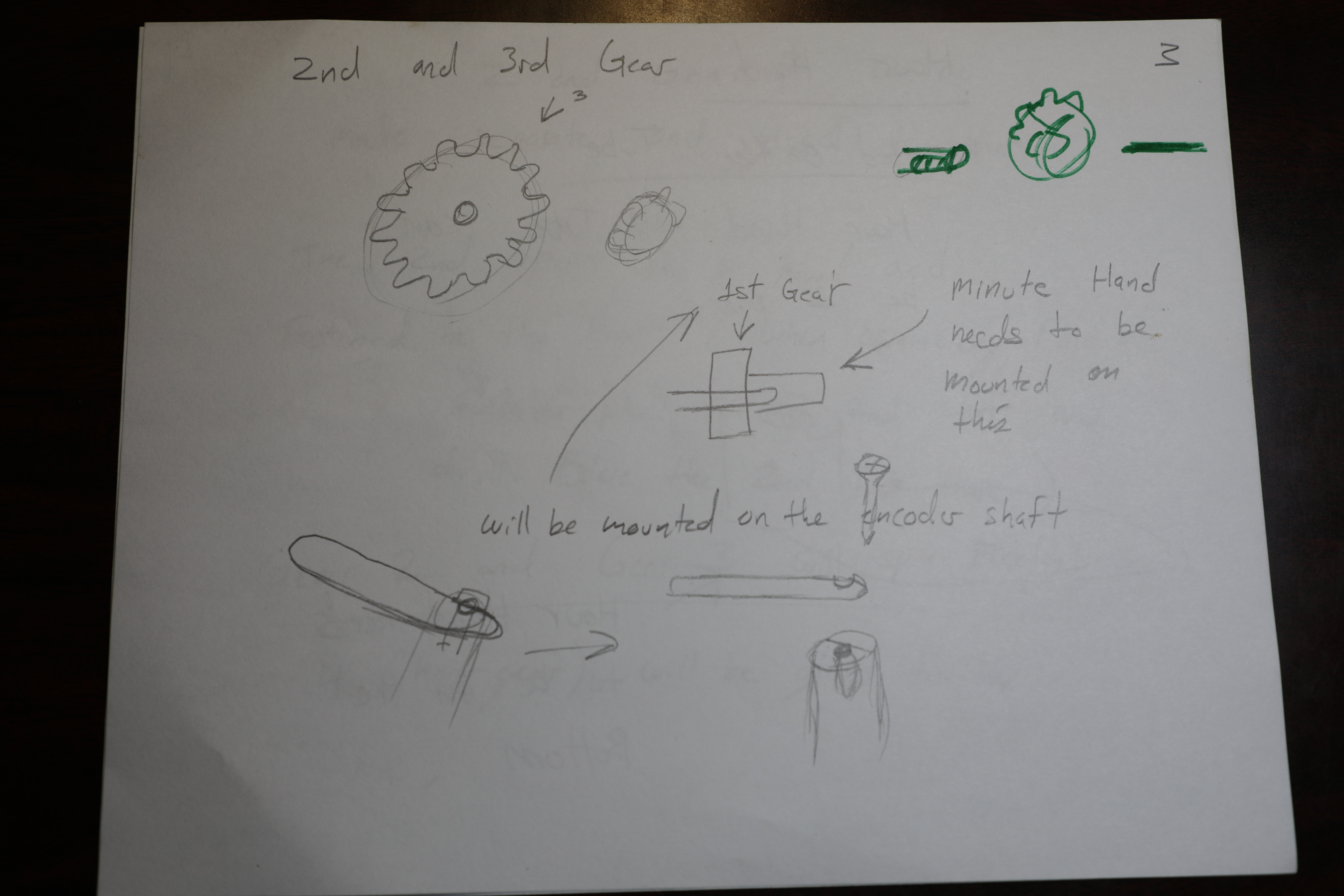
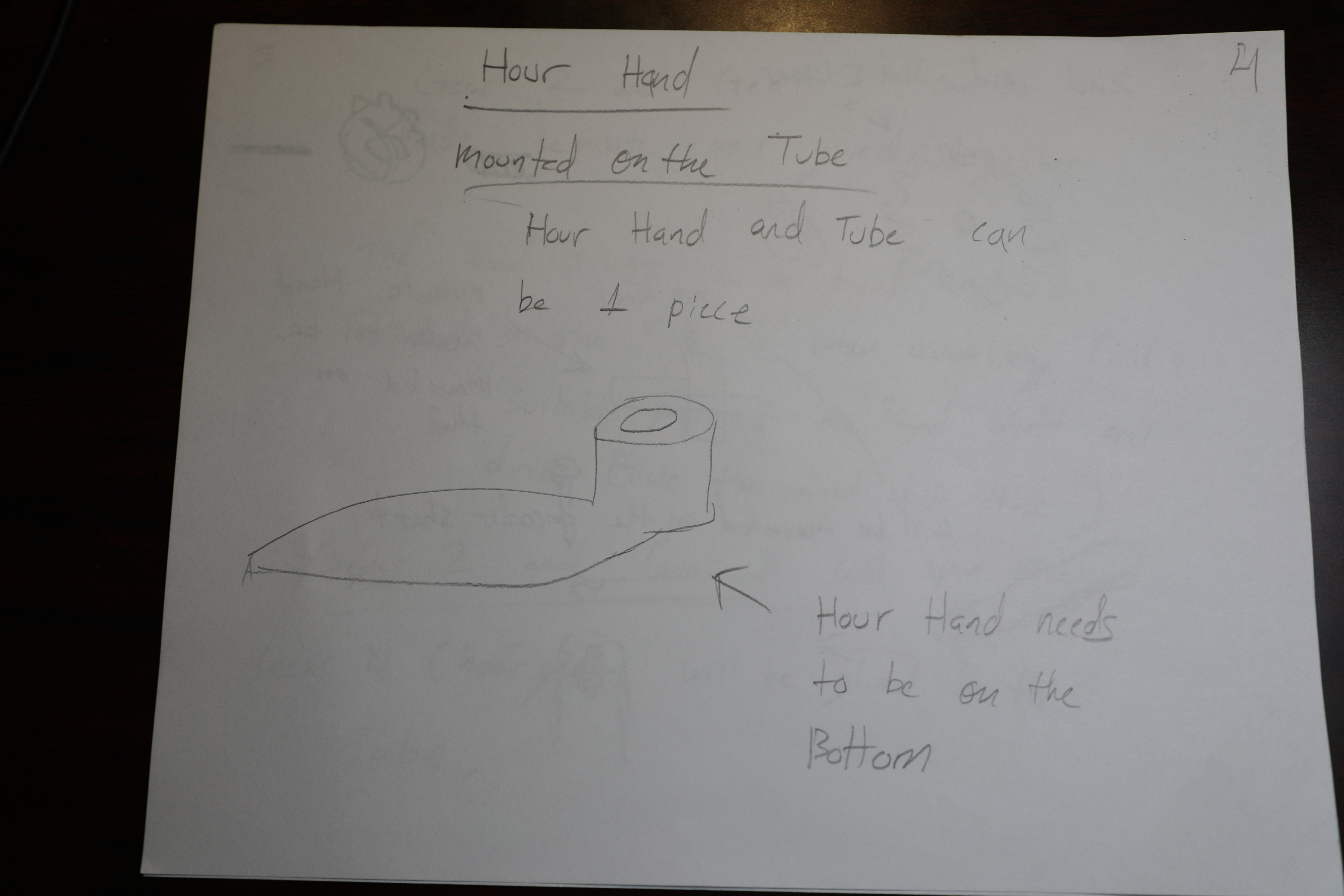
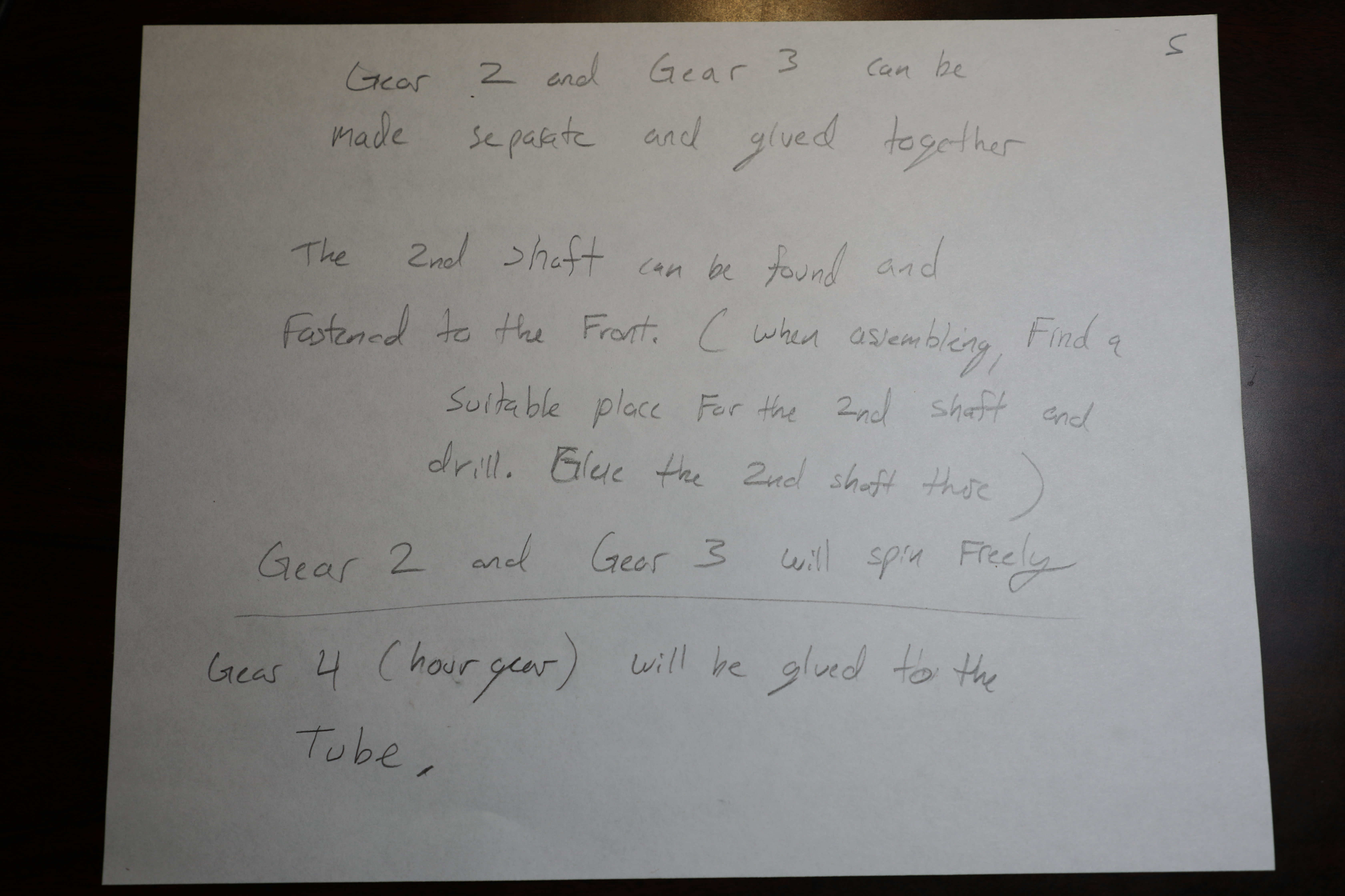
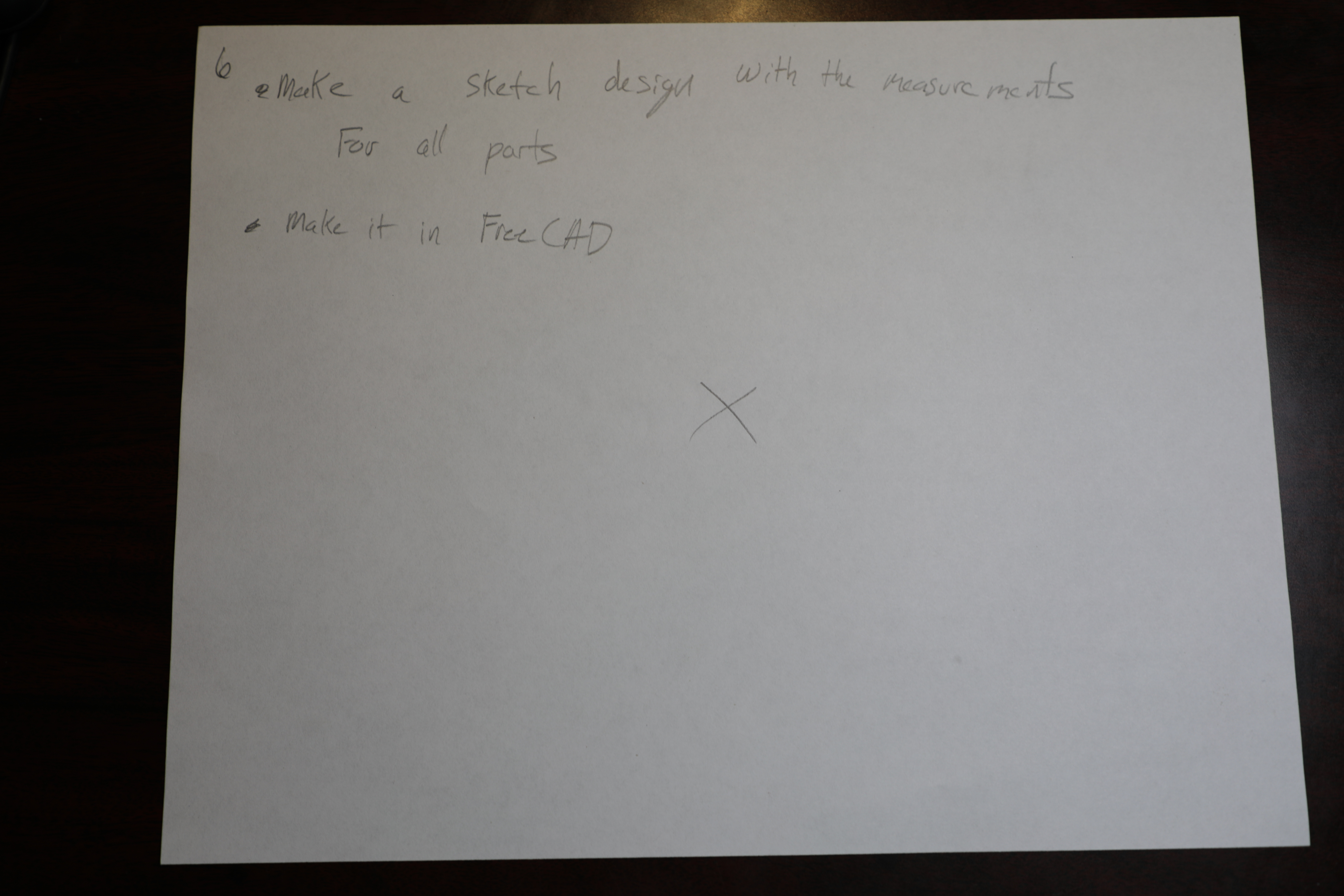
Yesterday, Plans were sketched out for the Design of the Minute hand and the hour hand and the corresponding gears. Such plans are pictured below, 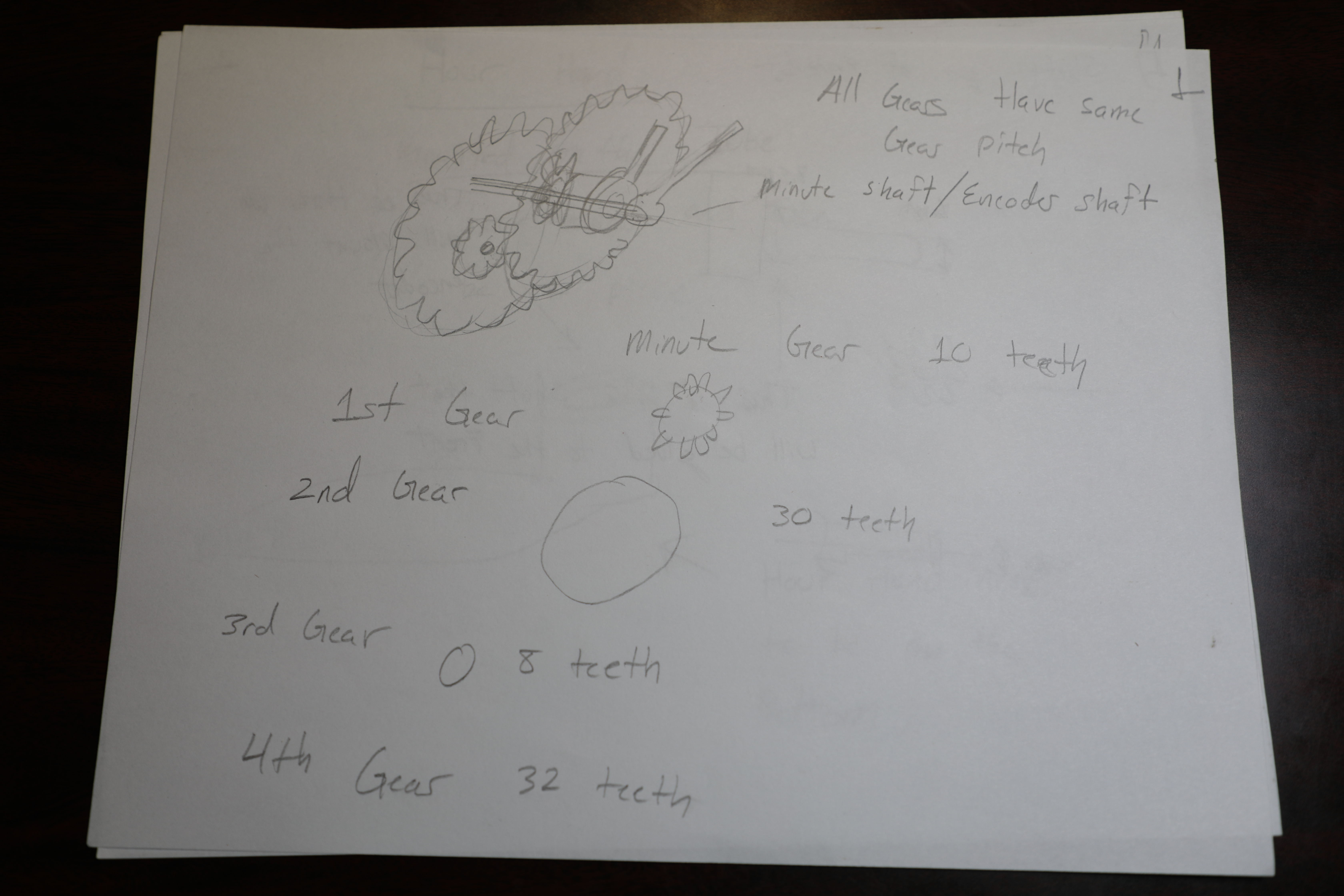
Several plywood panels were laser cut. 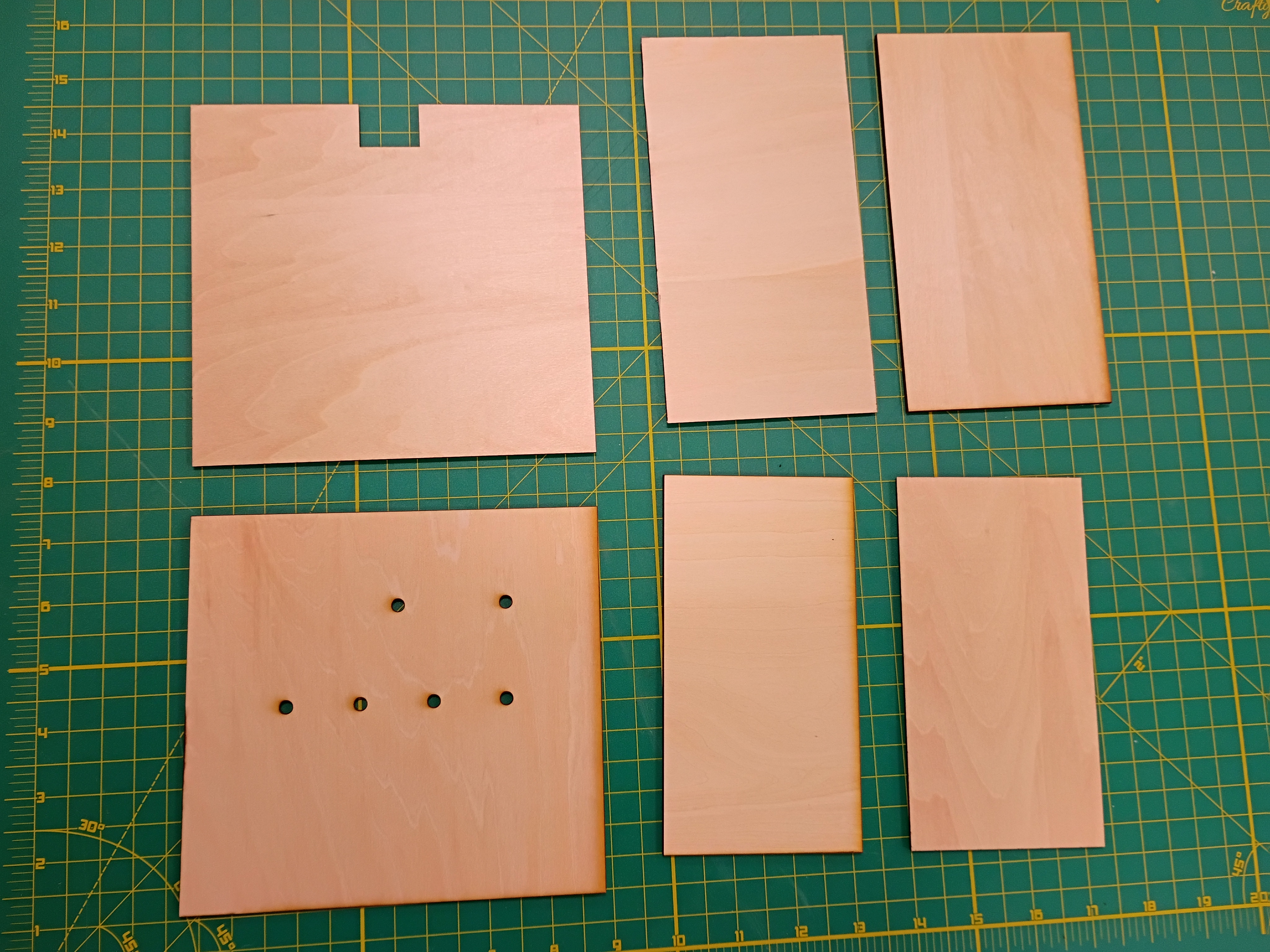
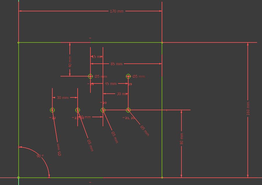
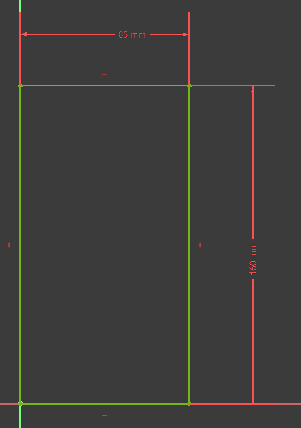
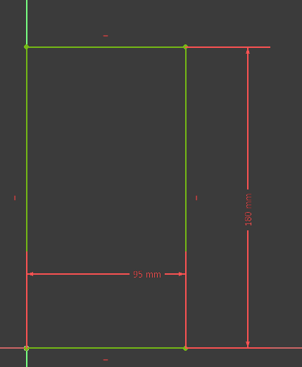
Made a rough sketch of the planning for the electronics encasement of MM1 Minute hand. 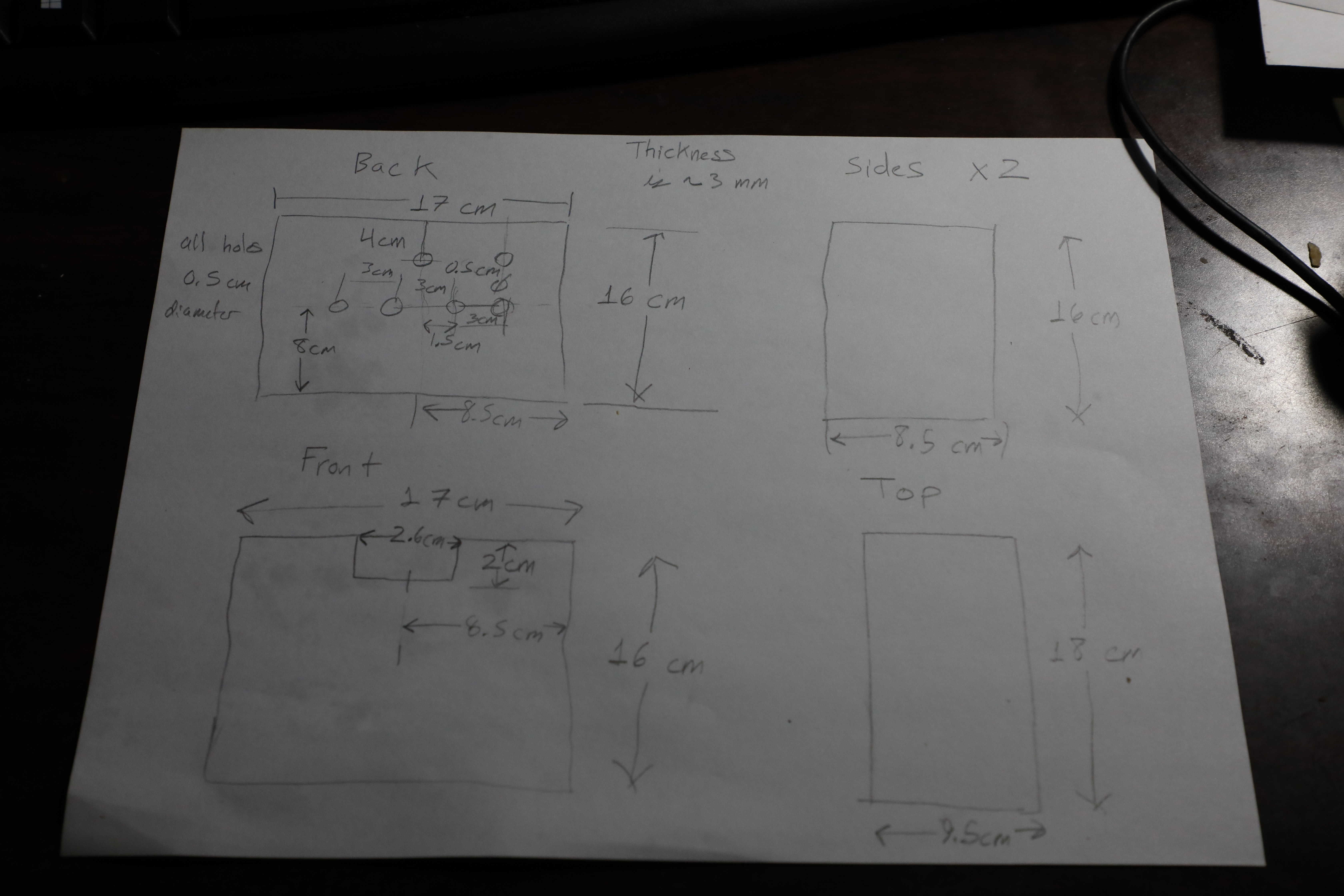
Received Packages yesterday for Testing and construction of the project. 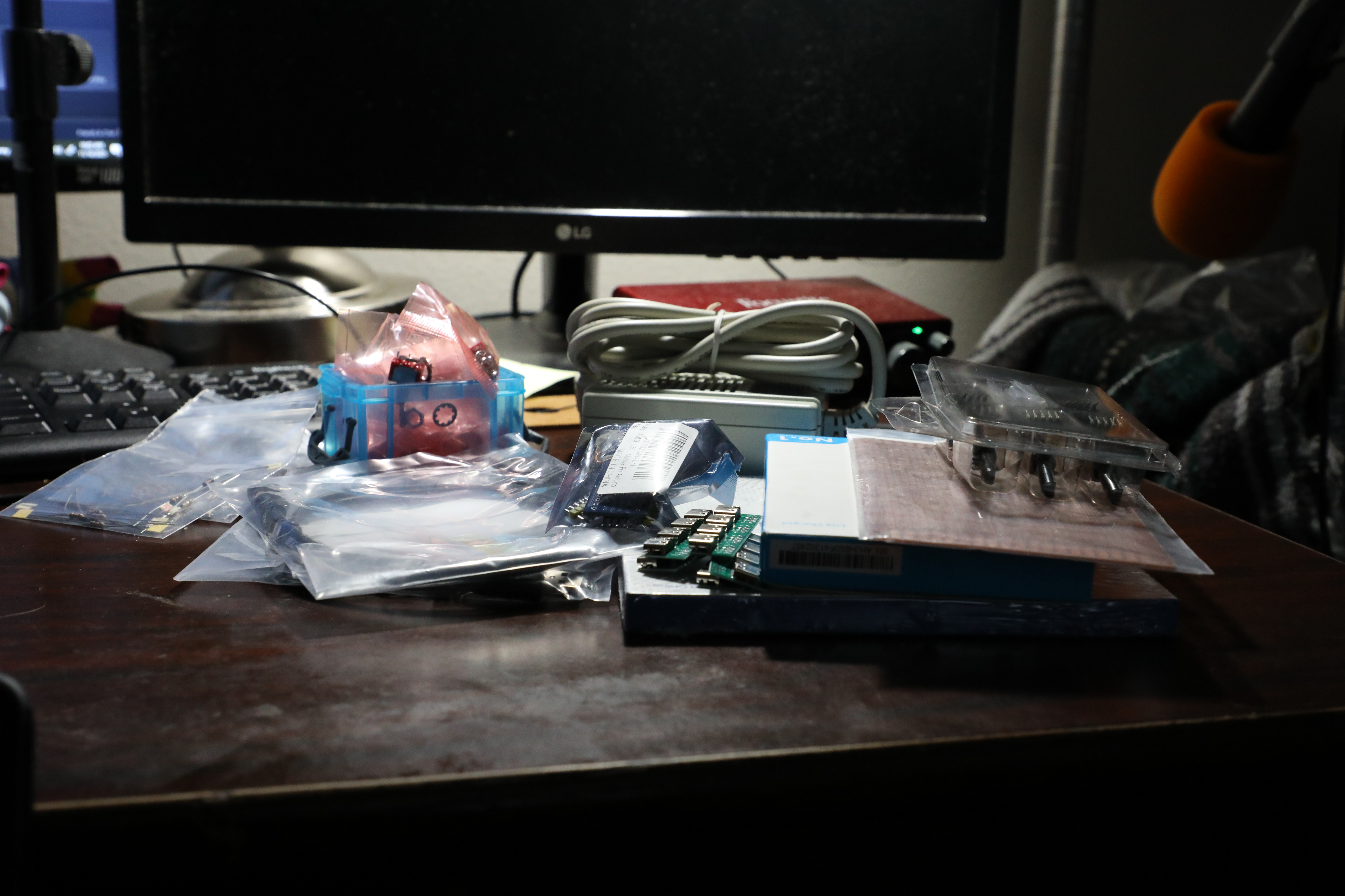
The Electrical Parts were accumulated in a list to order from Amazon and Mouser. The order was placed today November 13.
Researched More items for MM1 Minute Hand which include a portable power bank from Amazon. In addition Orders for a microcontroller and breadboards were also Researched.
researched Parts to order including: USB C cables, female USB C receiver, encoders, SPDT switches, Rechargeable Lead Acid Batteries, LiPo batteries.
Learned the basics of FreeCAD to design parts for Minute Hand.
Bought Perf Board, resistors, and a Power Supply for the Main circuit.