Added usage instructions and photos to the documentation linked by the product URL.
Set up automatic redirect from https://www.marian-scientific.org/22001 to the corresponding folder of the GitHub project repository. Also updated the code and documentation to match.
Completed fabrication of serial number 002 and shipped to our sister facility for future product development. See video of it working during QC testing. it does look pretty snazzy.
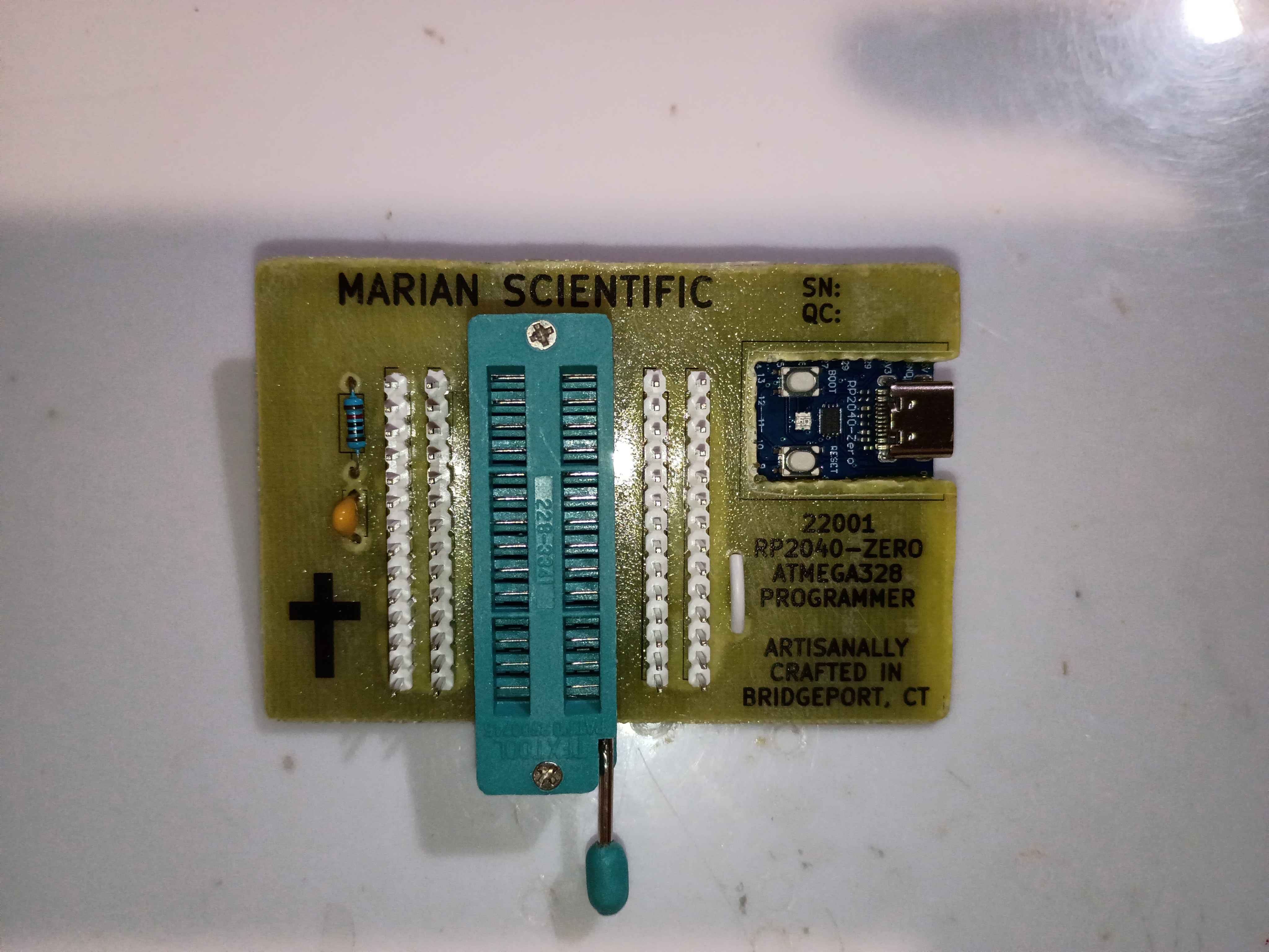
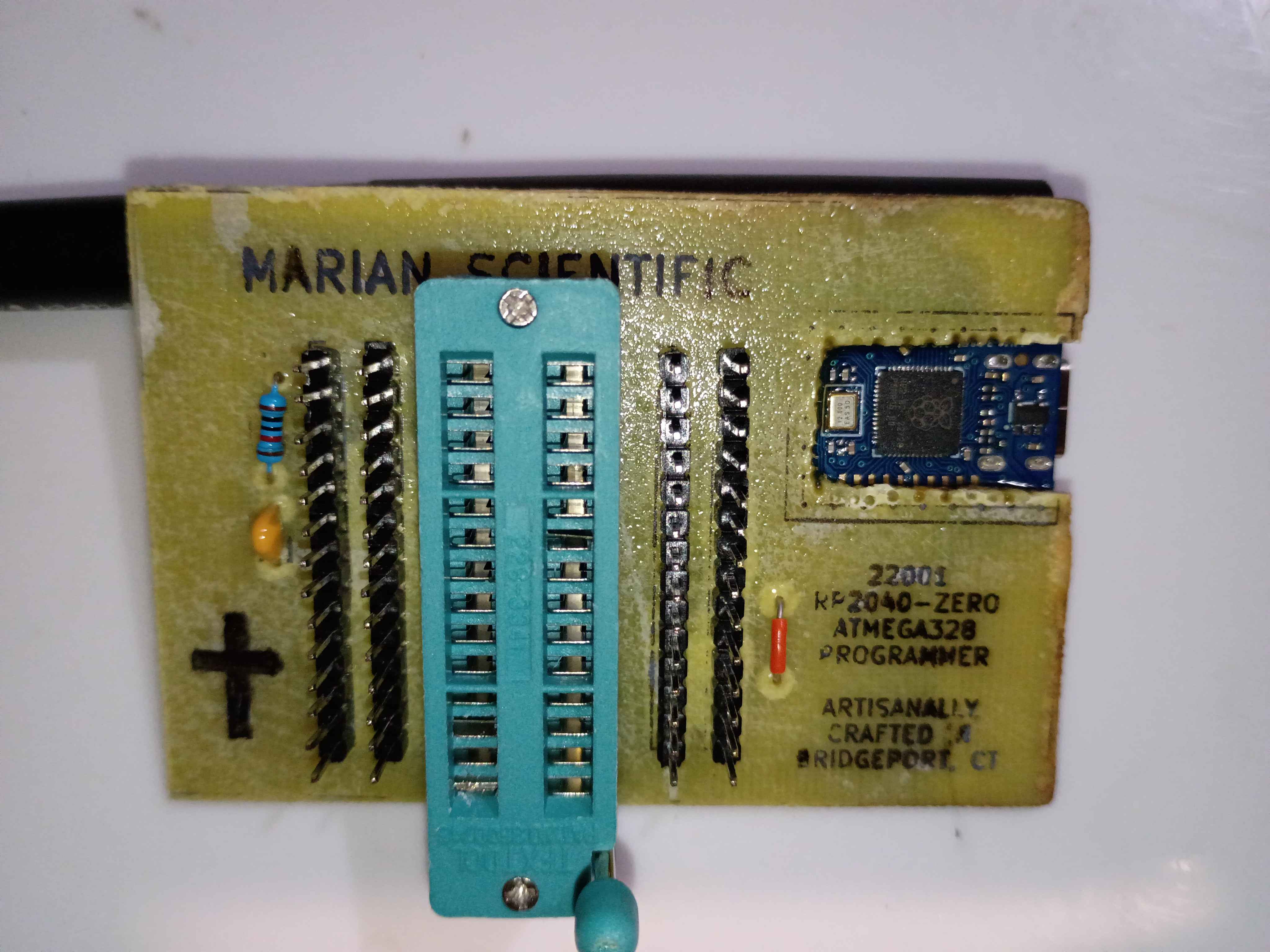
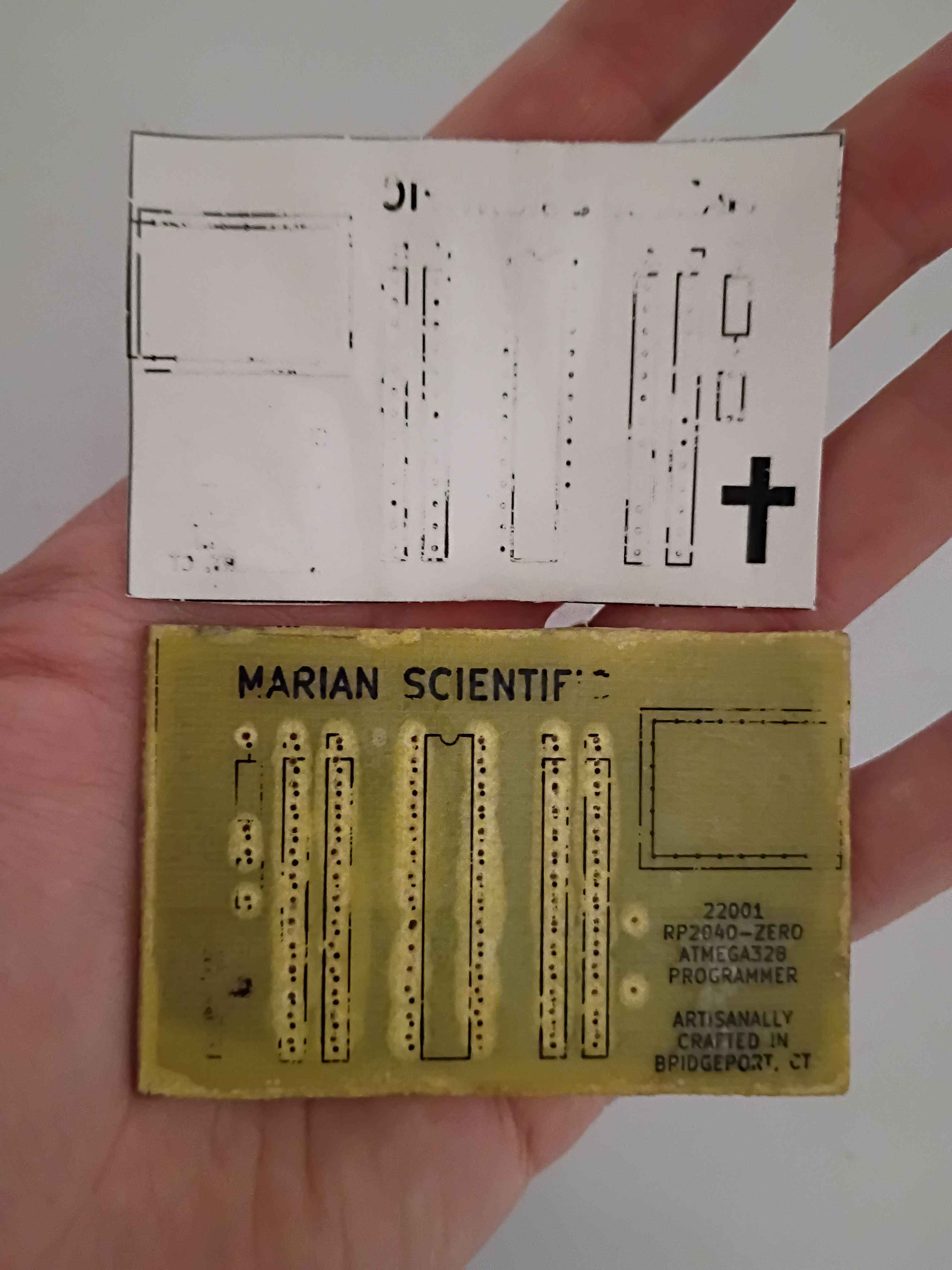
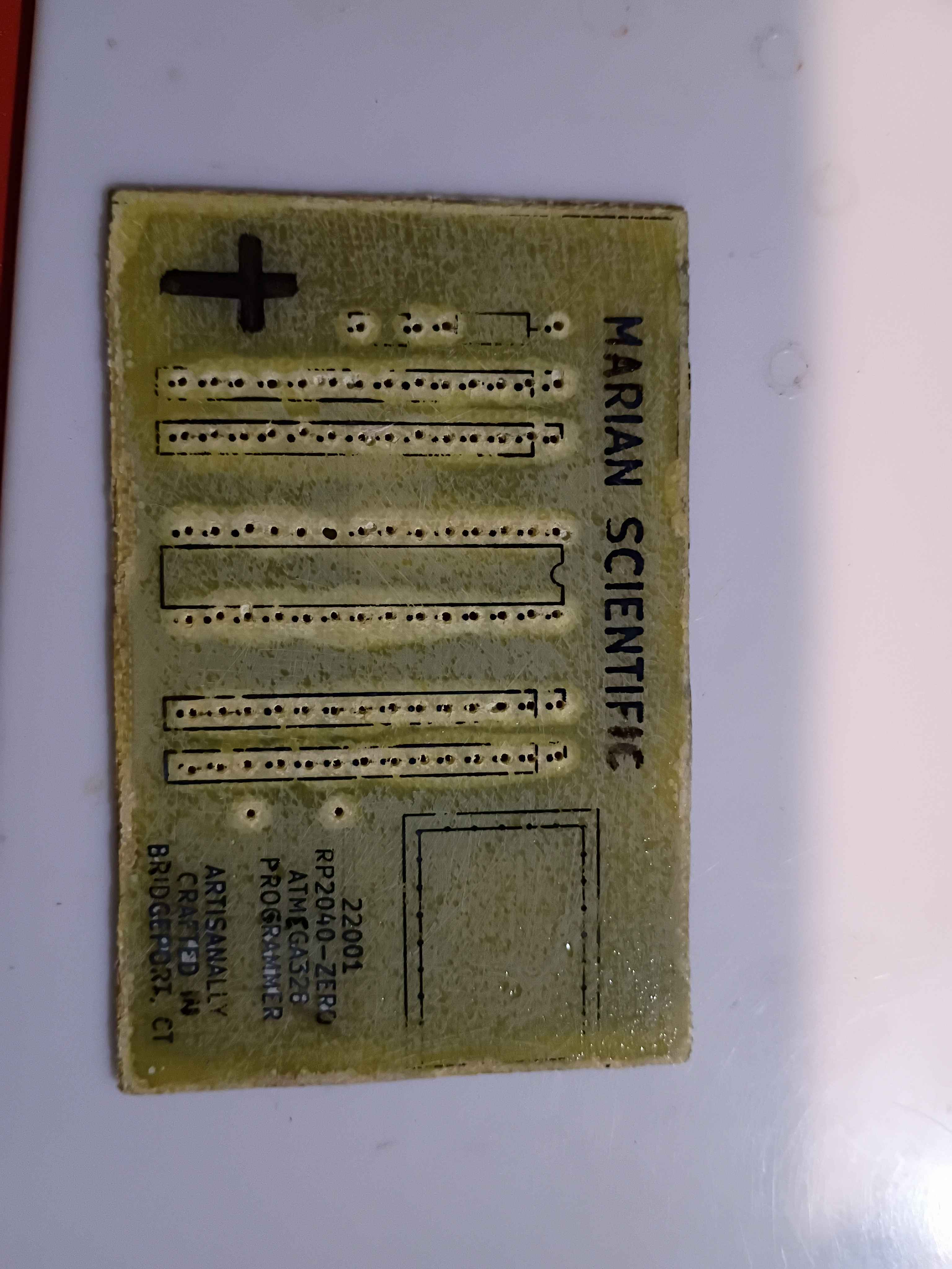
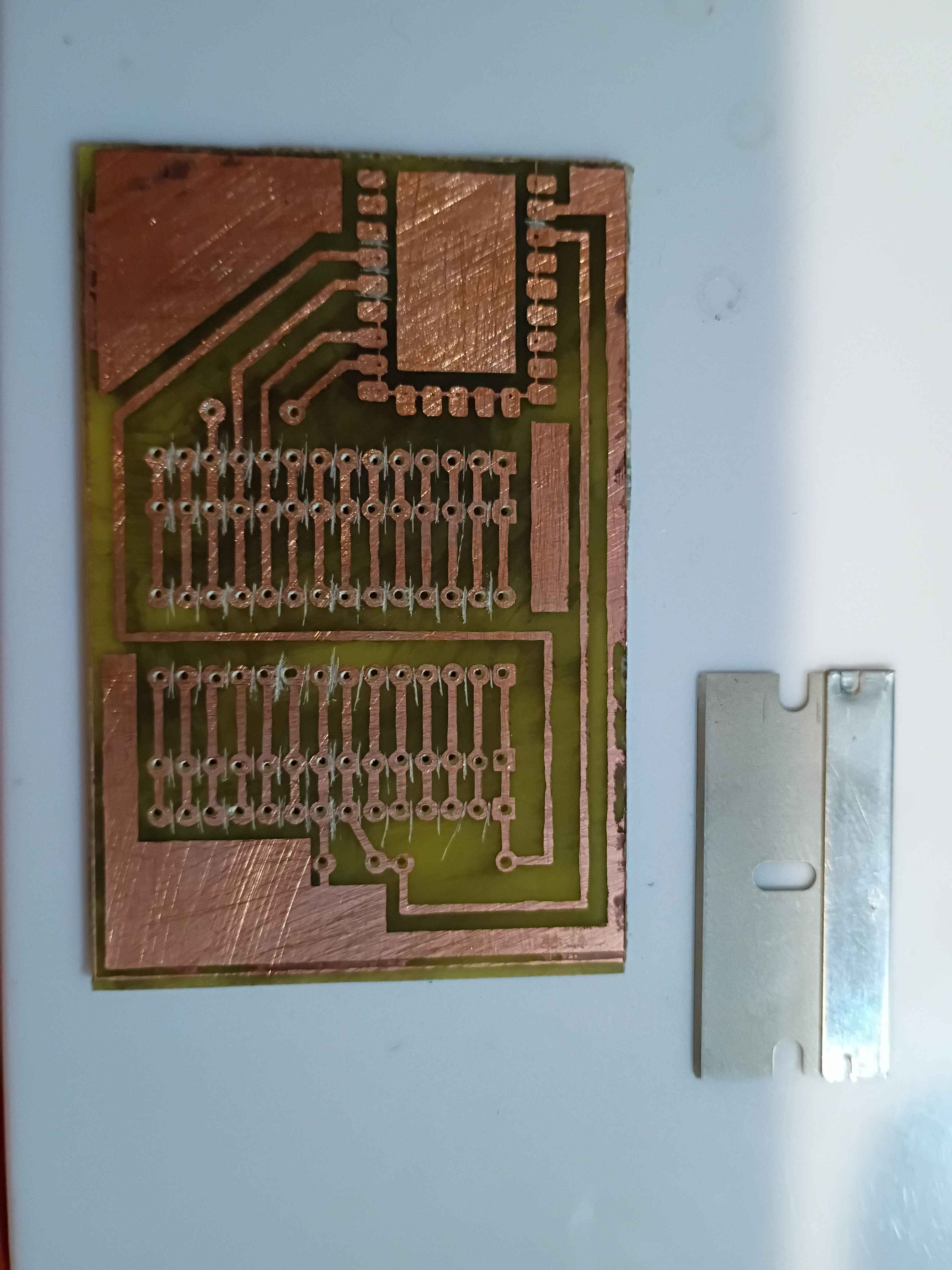
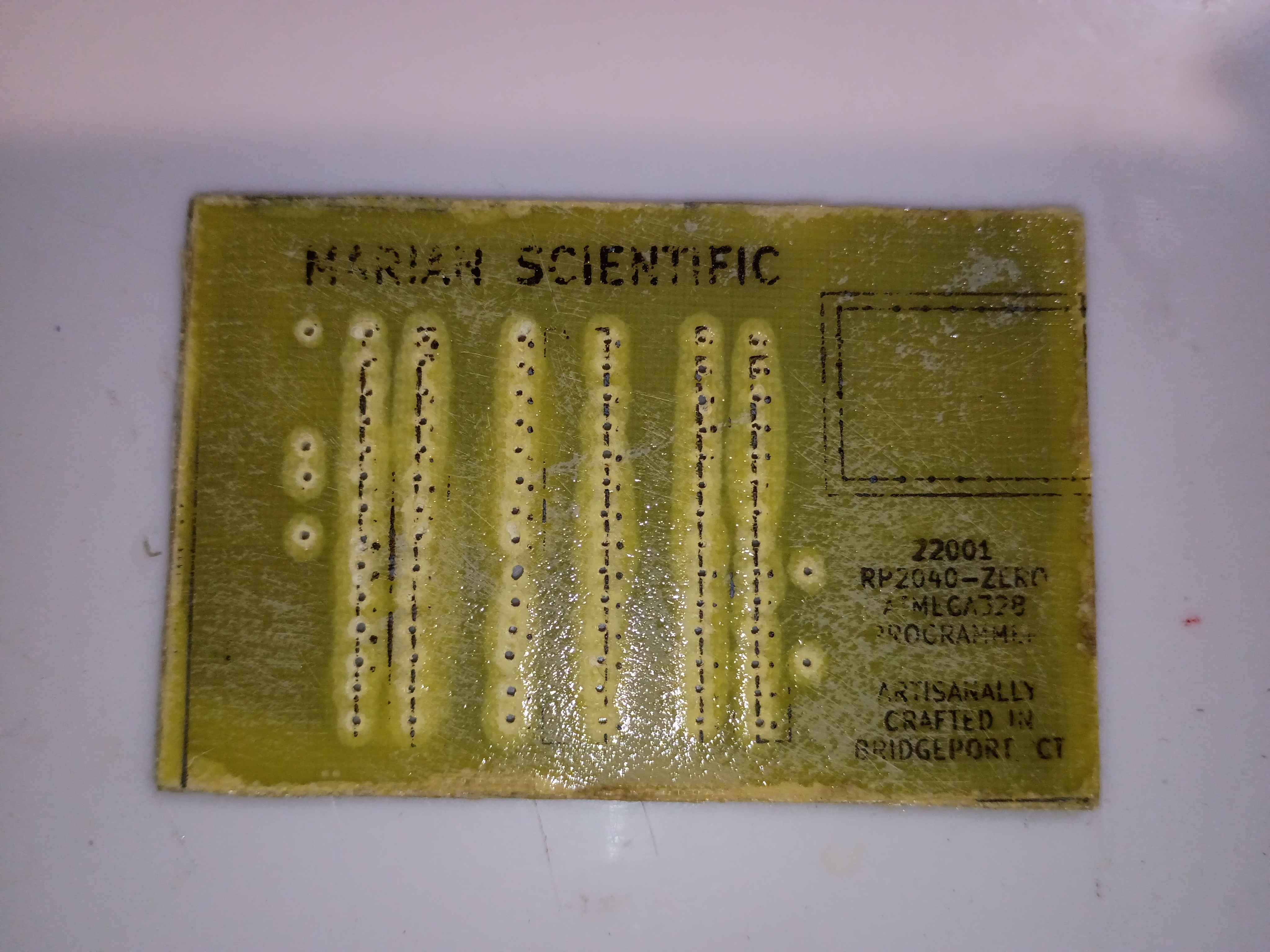
Attempting to make an improved version to provide for internal R&D efforts. Updated the PCB design to improve the text spacing on the F.Silkscreen and add a spot for serialization. Etched another PCB and drilled thru holes, slightly nicer than the previous one in a few different ways. Attempted in vain to toner transfer the silkscreen onto the front face for the final time. Decided to just use a sticker for the foreseeable future, as it's not worth the effort for toner, and it's less robust anyway. Just waiting on some ZIF sockets before I can assemble. 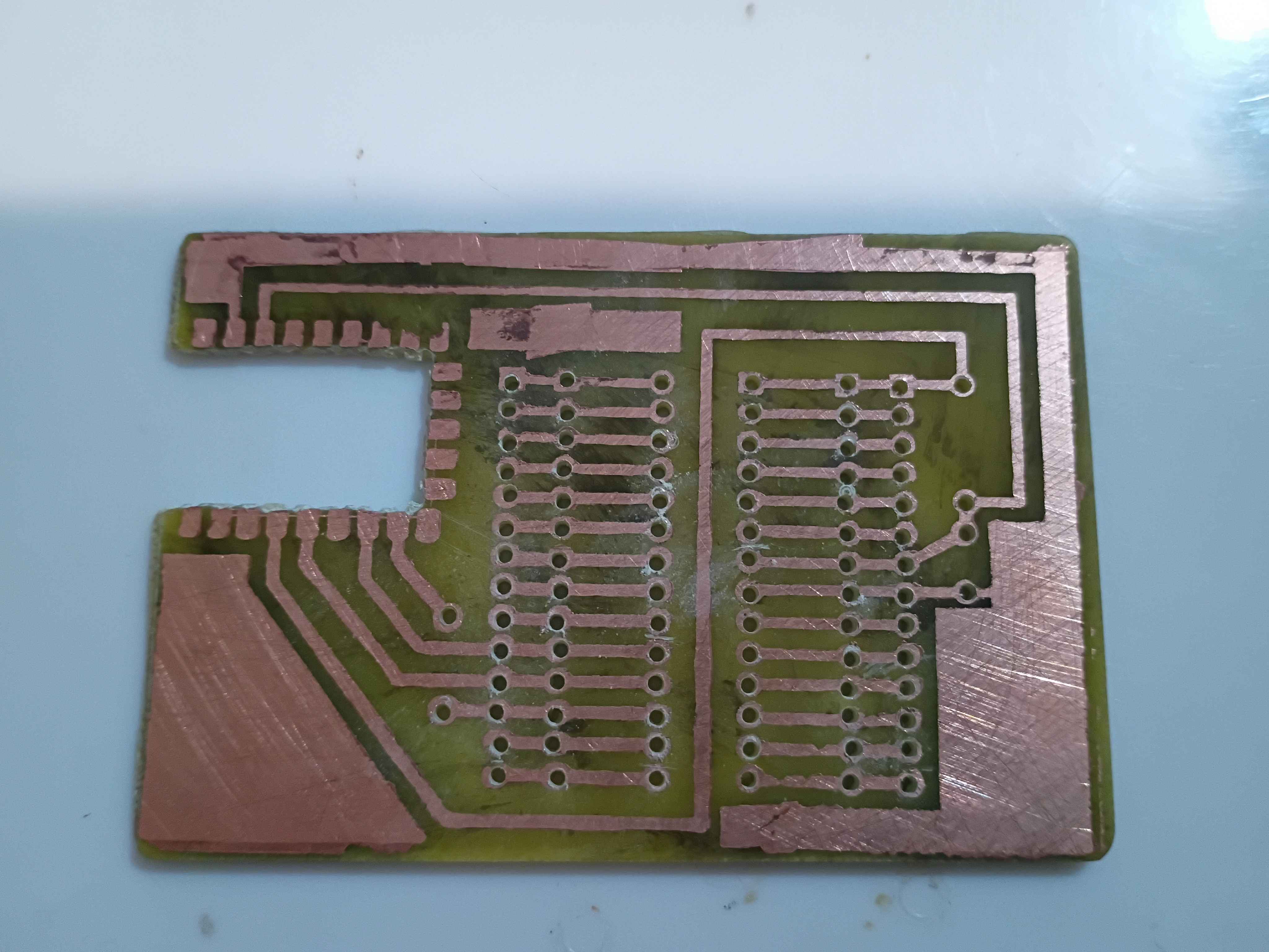
I re-soldered the RP2040-Zero board right-side-up, but the programmer still wasn't working. After a shameful 2 hours of debugging, I finally realized I must have fried some magic pixie gems inside the RP2040 by soldering it and running it the wrong way around, so I popped a new one in and it worked a treat. Project complete! See video of it working. If I make another one of these, I will try to do the toner transfer better. It might even warrant an investigation into the heat and pressure levels that give the best results. 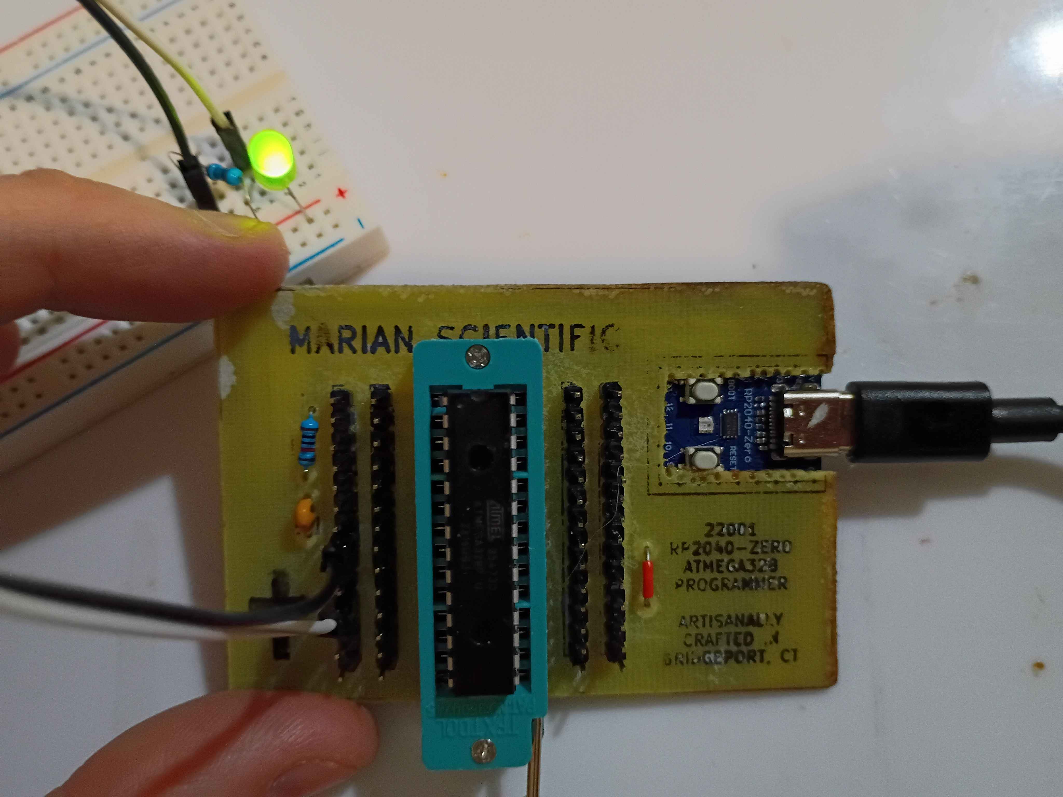
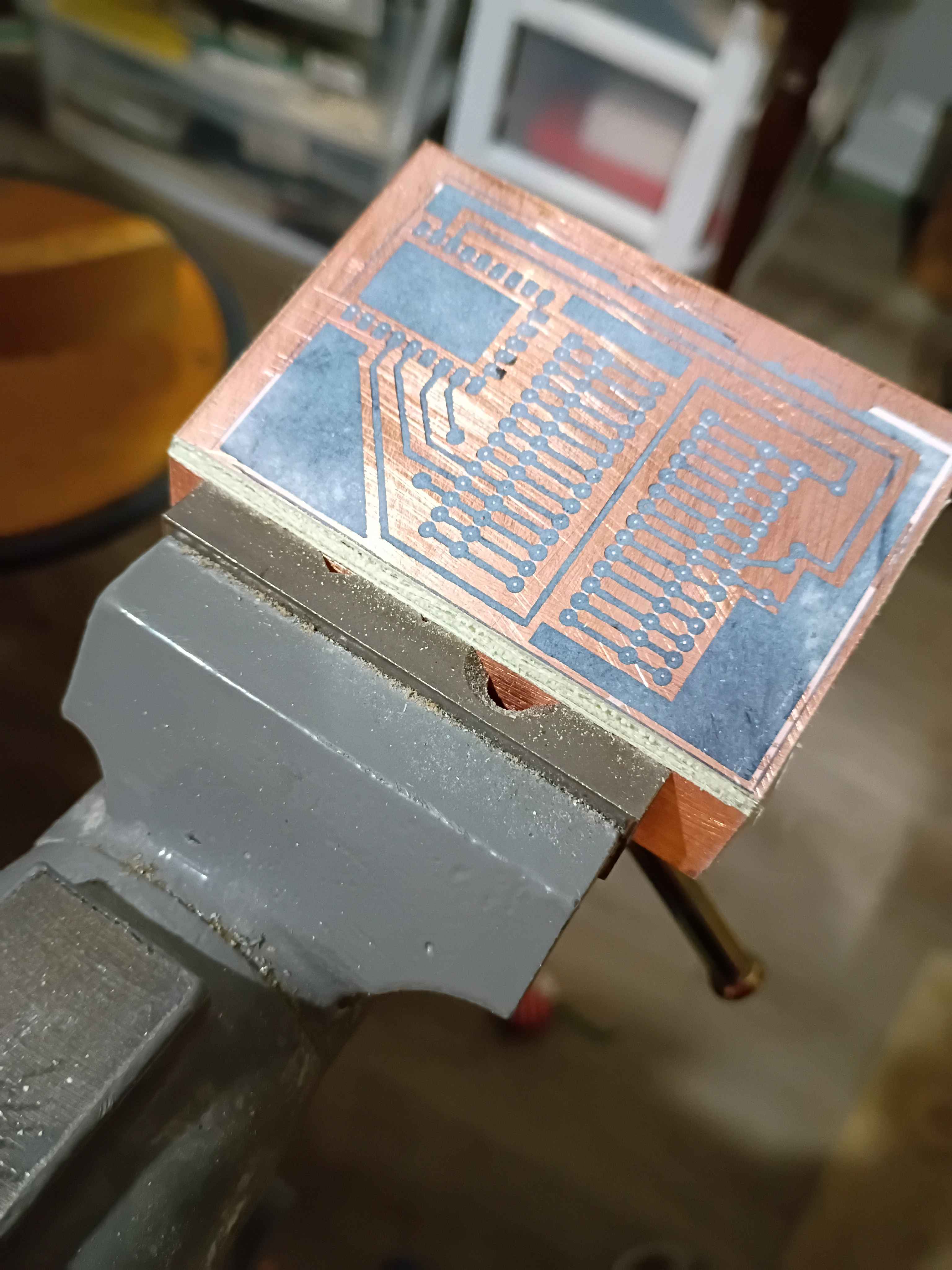
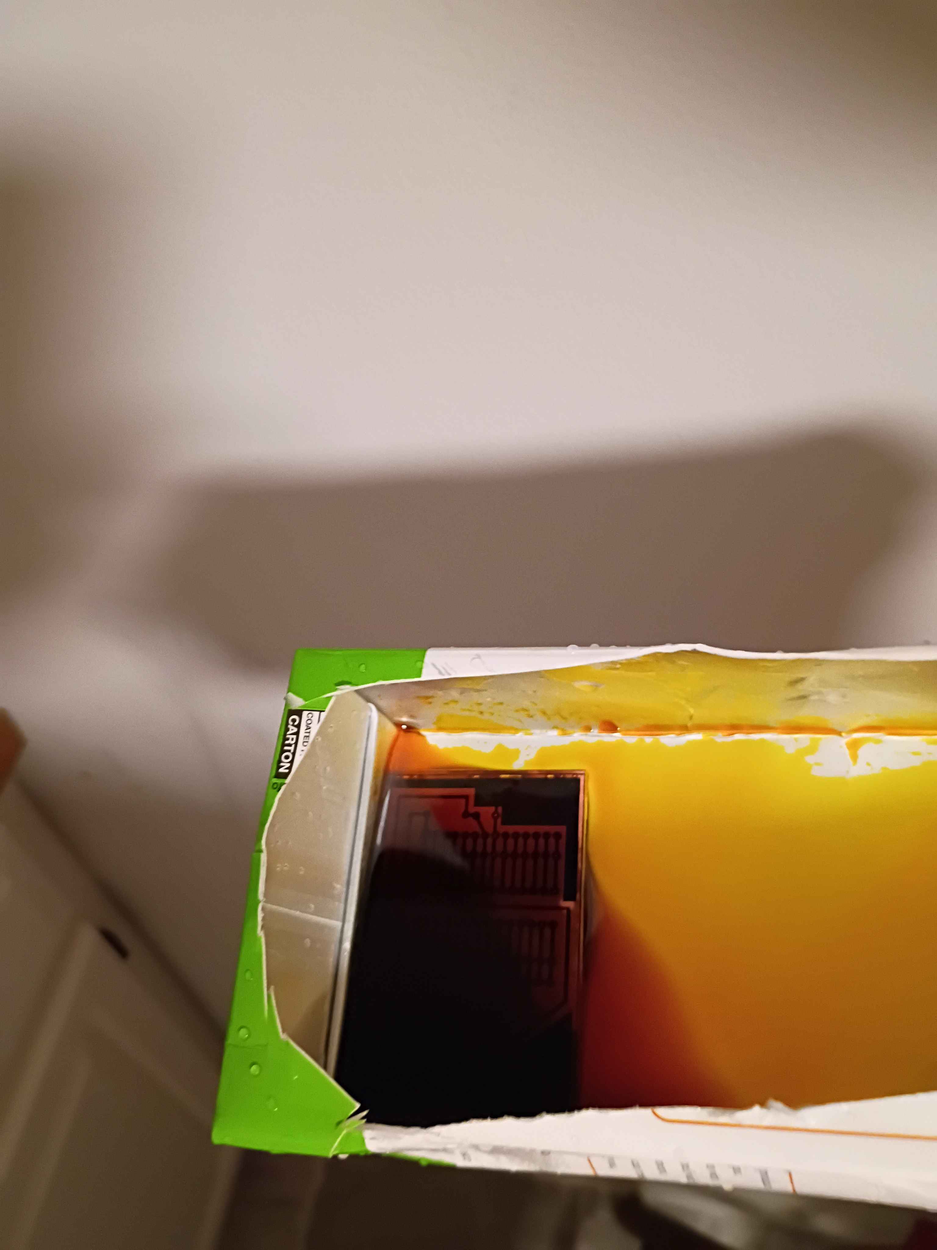
I redid the toner transfer of the B.Cu mask. For the areas that didn't transfer properly, I put some blue masking tape, 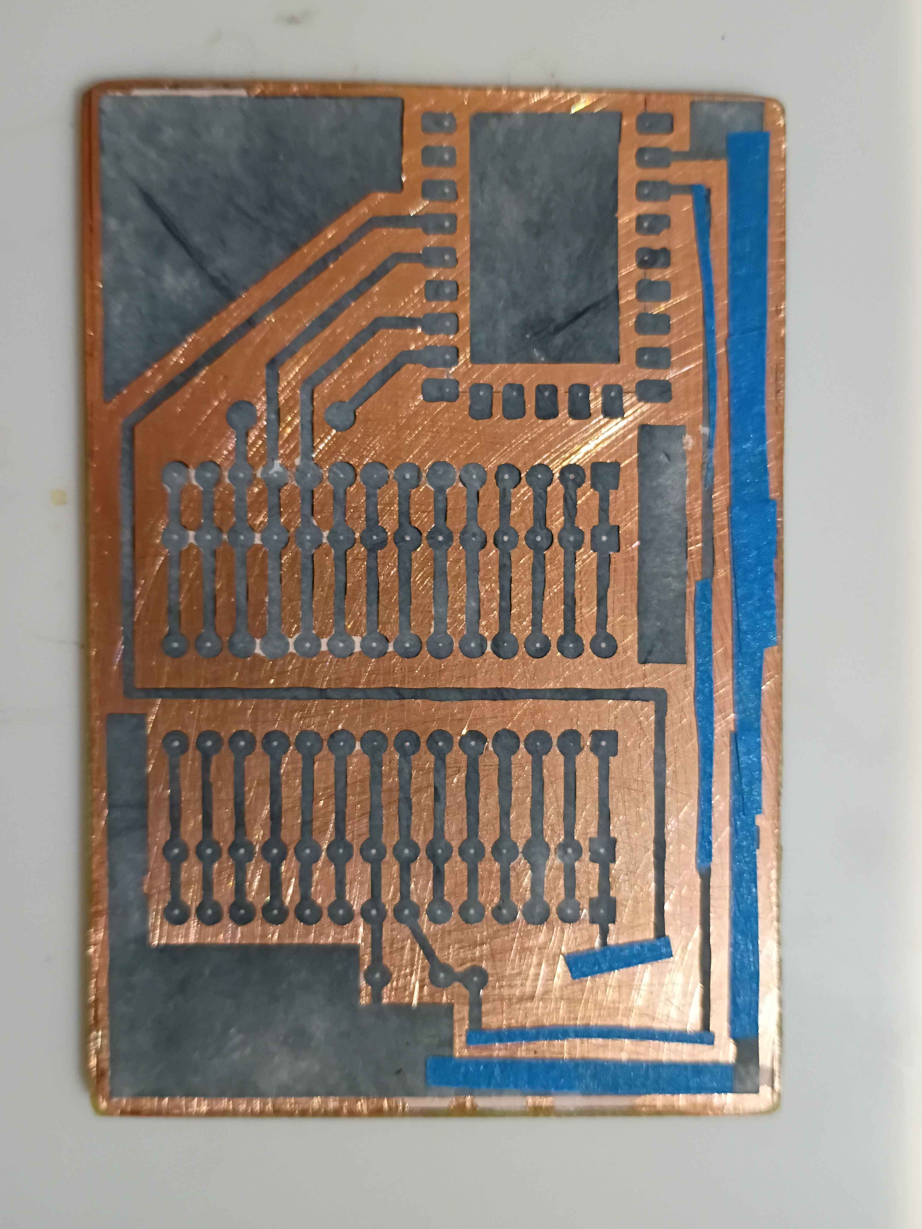
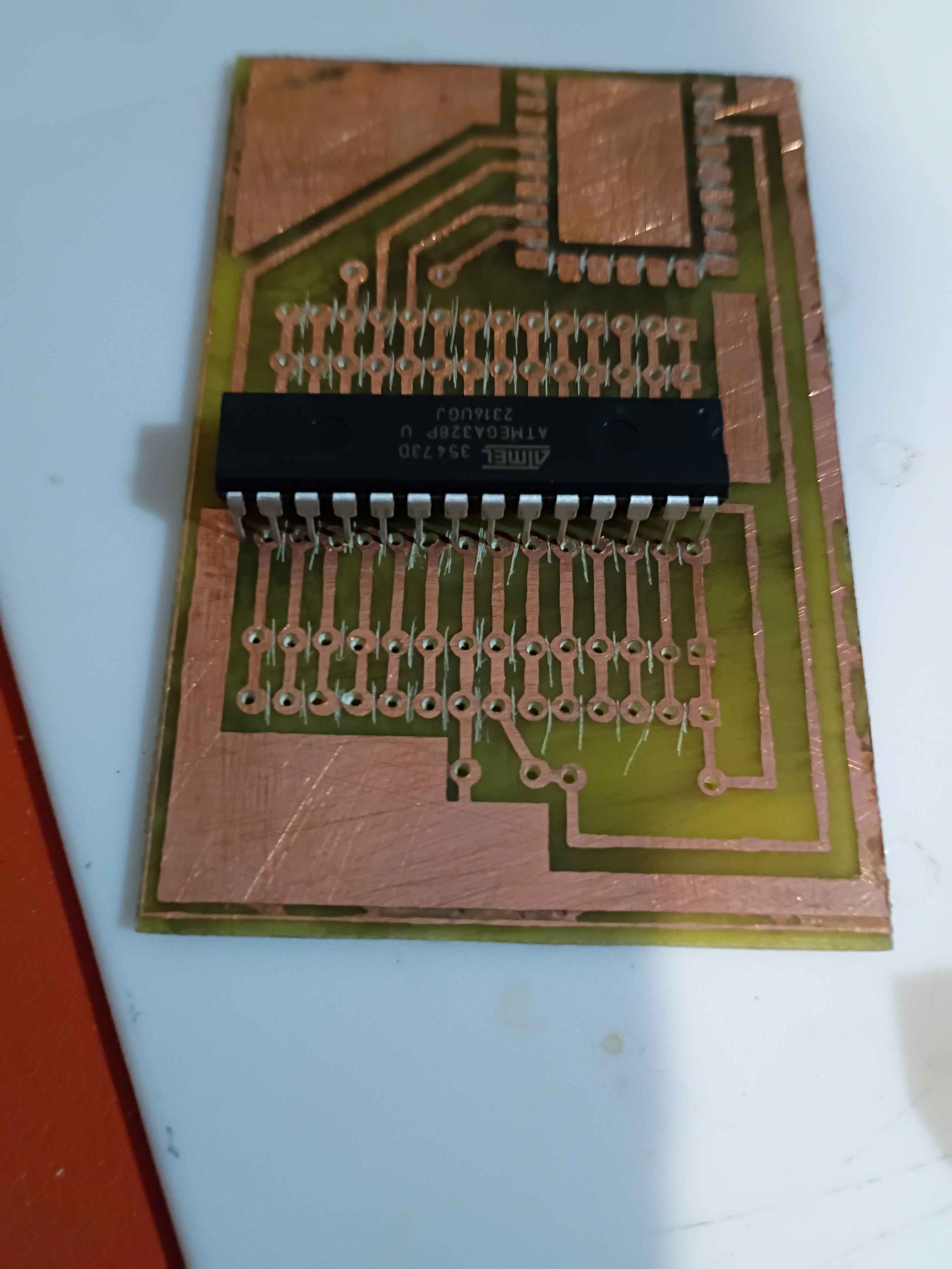
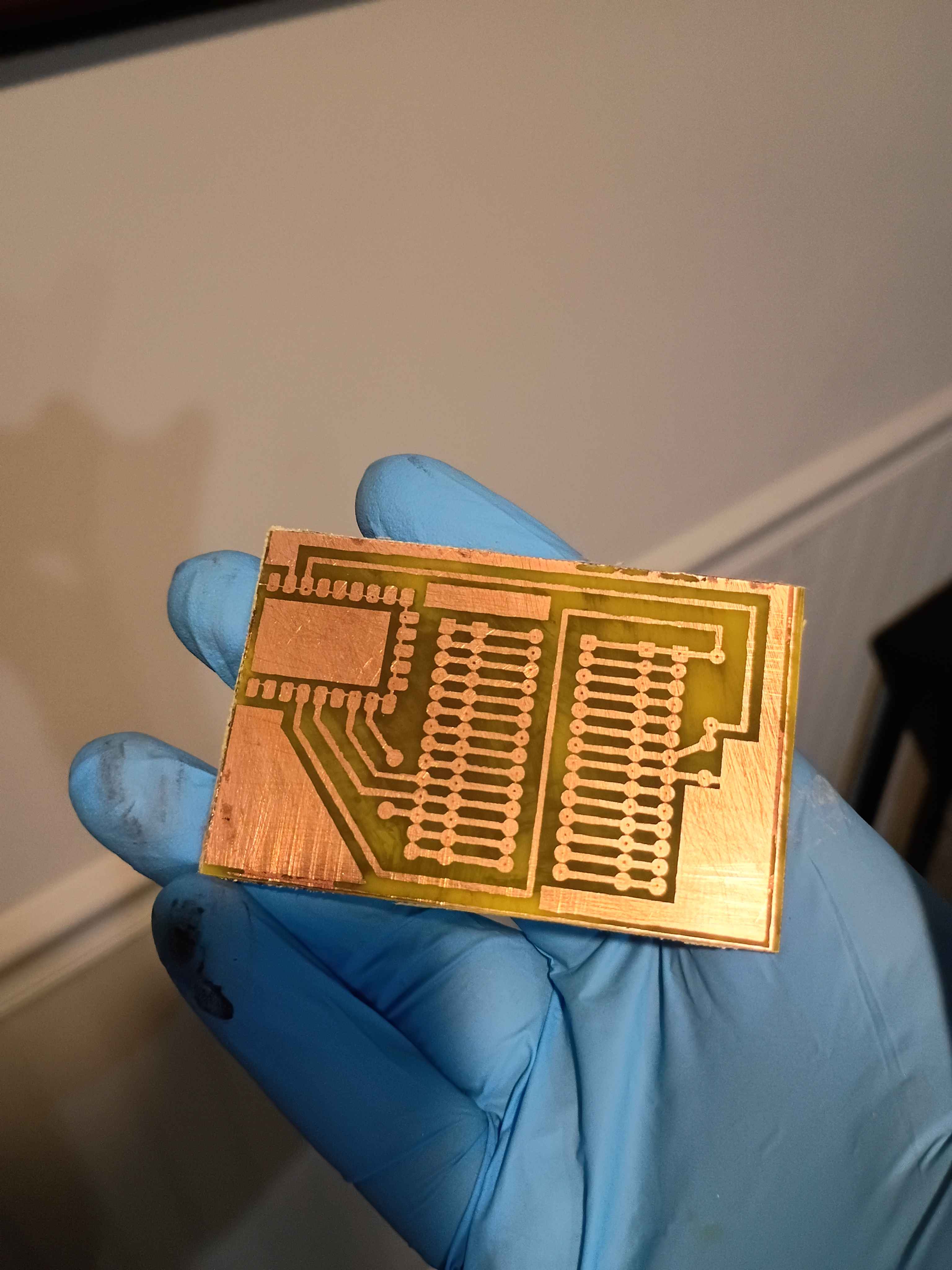
and that worked surprisingly well. I drilled out all the holes and even cut away the rectangle for the RP2040-Zero board. 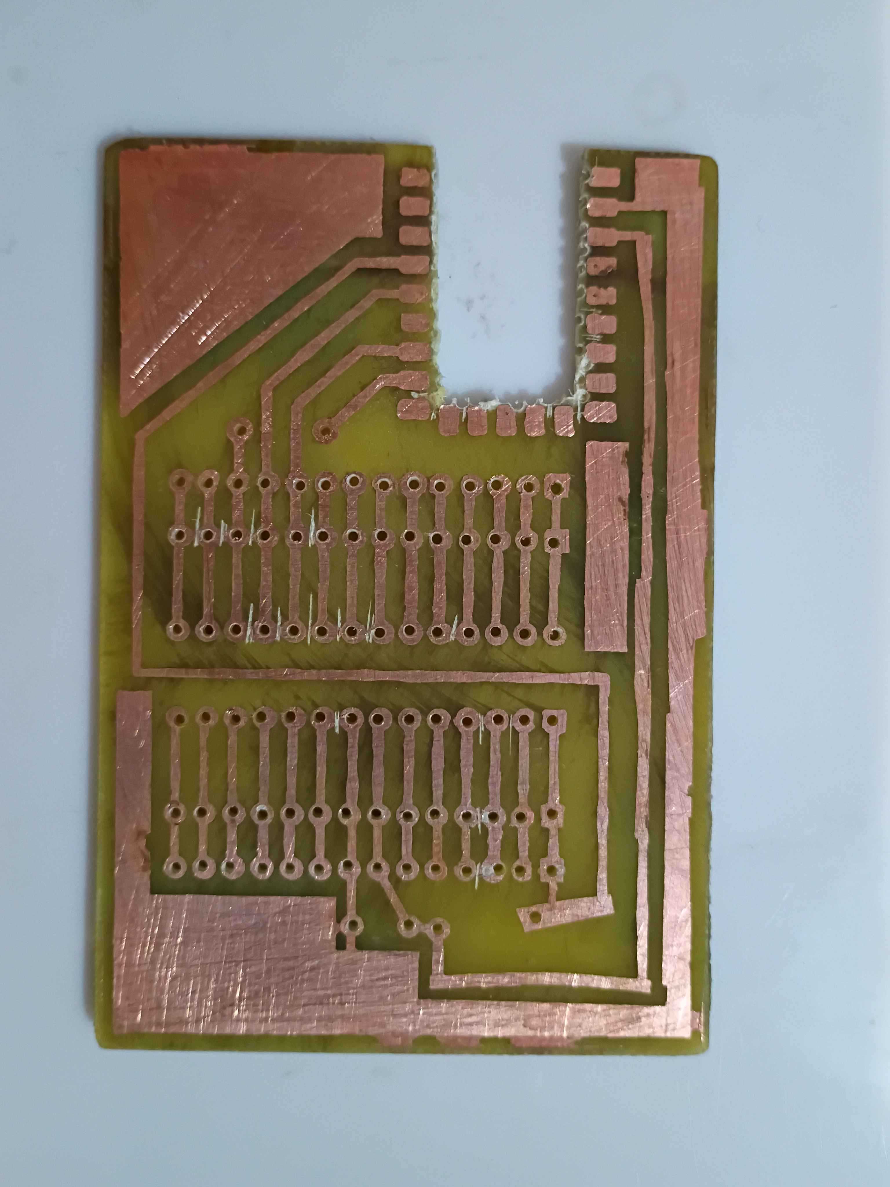
The toner transfer for the F.Silkscreen was not so successful even after a couple of attempts. I think it's because I sanded the fiberglass. I just retraced the parts that didn't transfer with black marker. 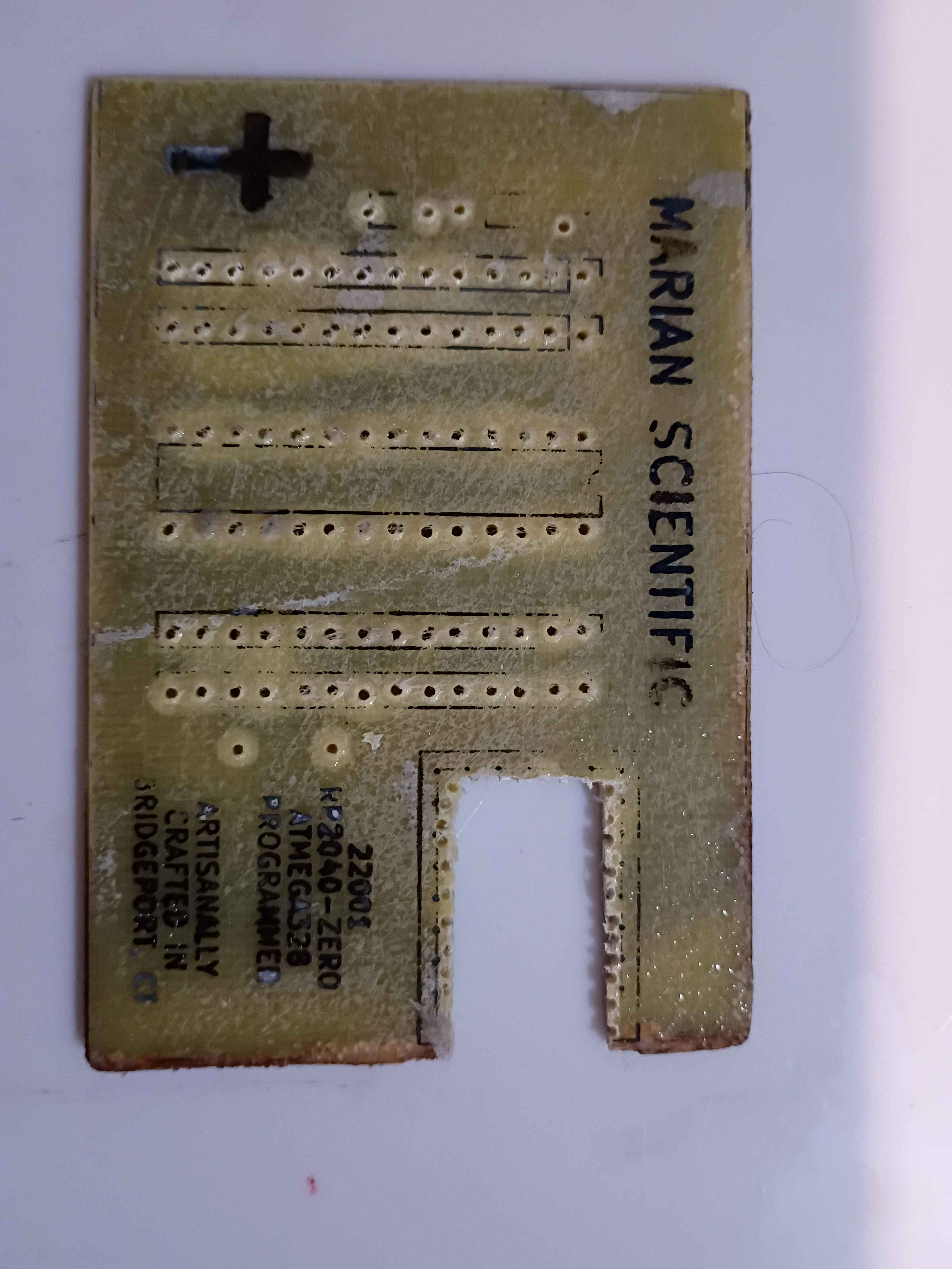
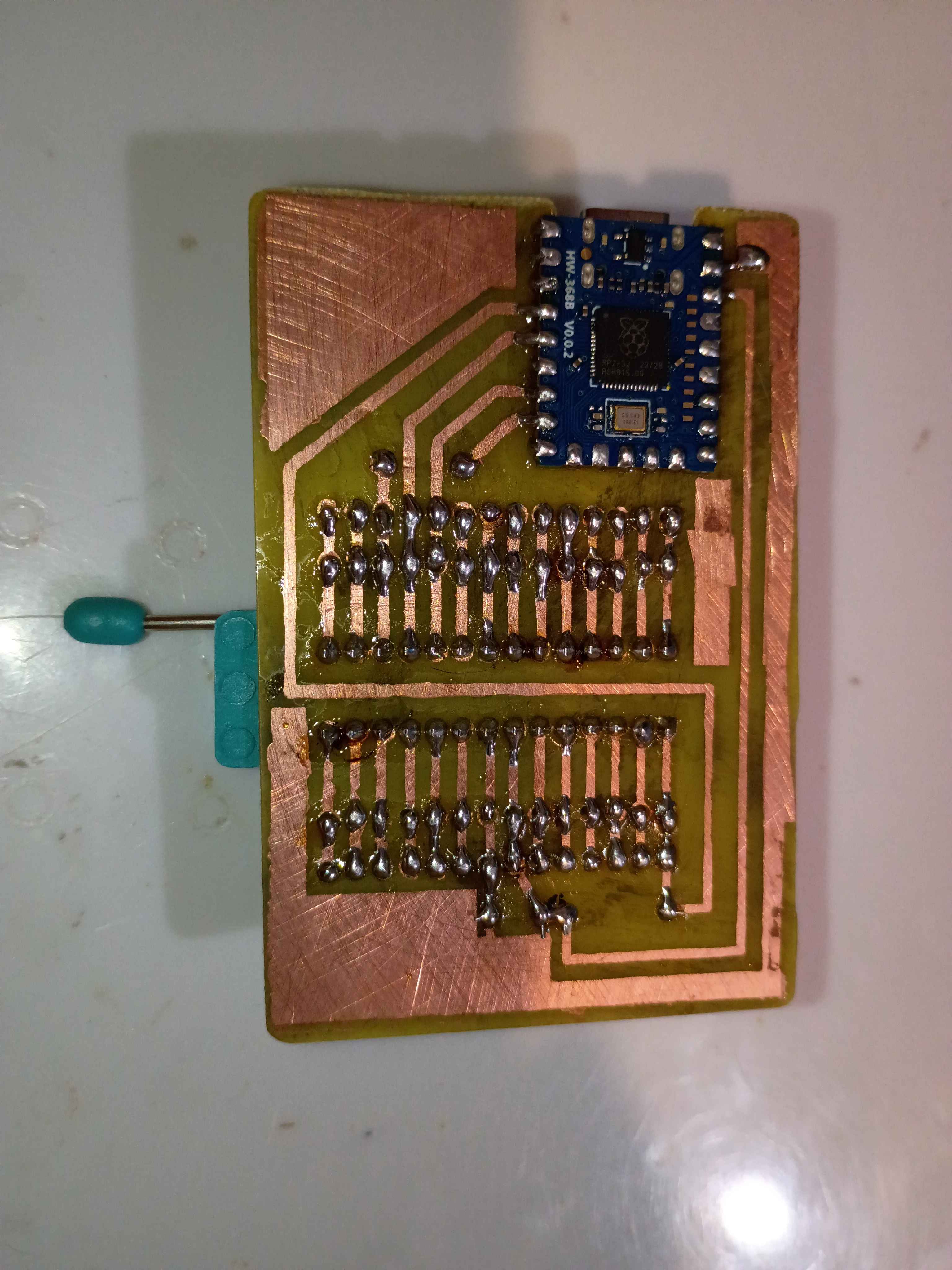
I soldered the components to the board, and it all looks great, until you realize I soldered the RP2040 board inside-out... I need to fix that tomorrow. 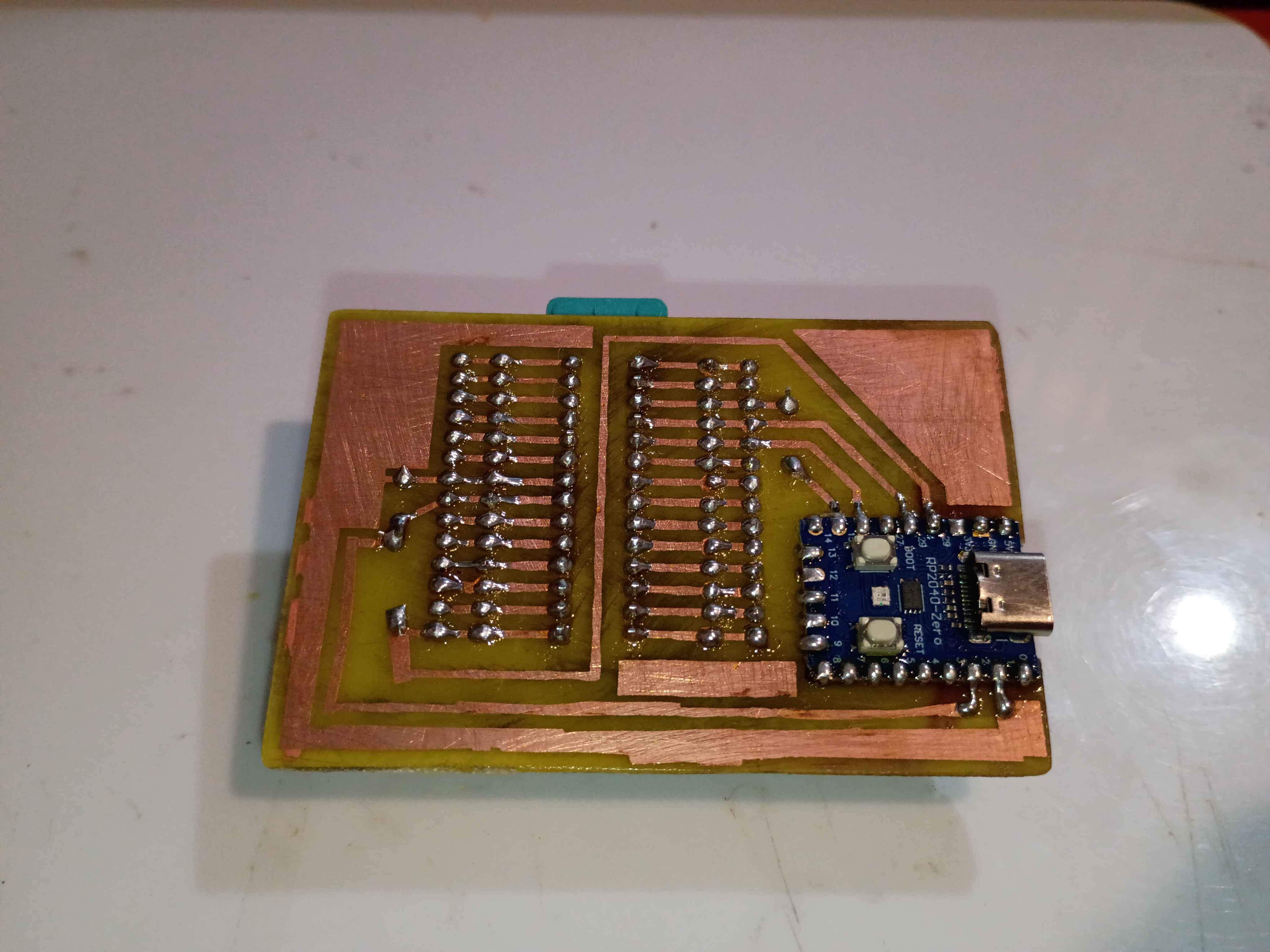
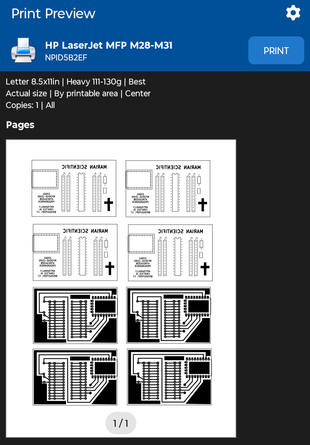
Sigh, apparently printing the PCB mask PDFs from my phone was a bad idea, since it automatically resized them down a few percent to "Fit to Page", and now none of the components fit, rendering a few hours of work yesterday and today completely wasted, except of course the practice etching and the lesson learned.
I reprinted the PDF with "Actual Size" scaling using the NokoPrint app and the settings below.
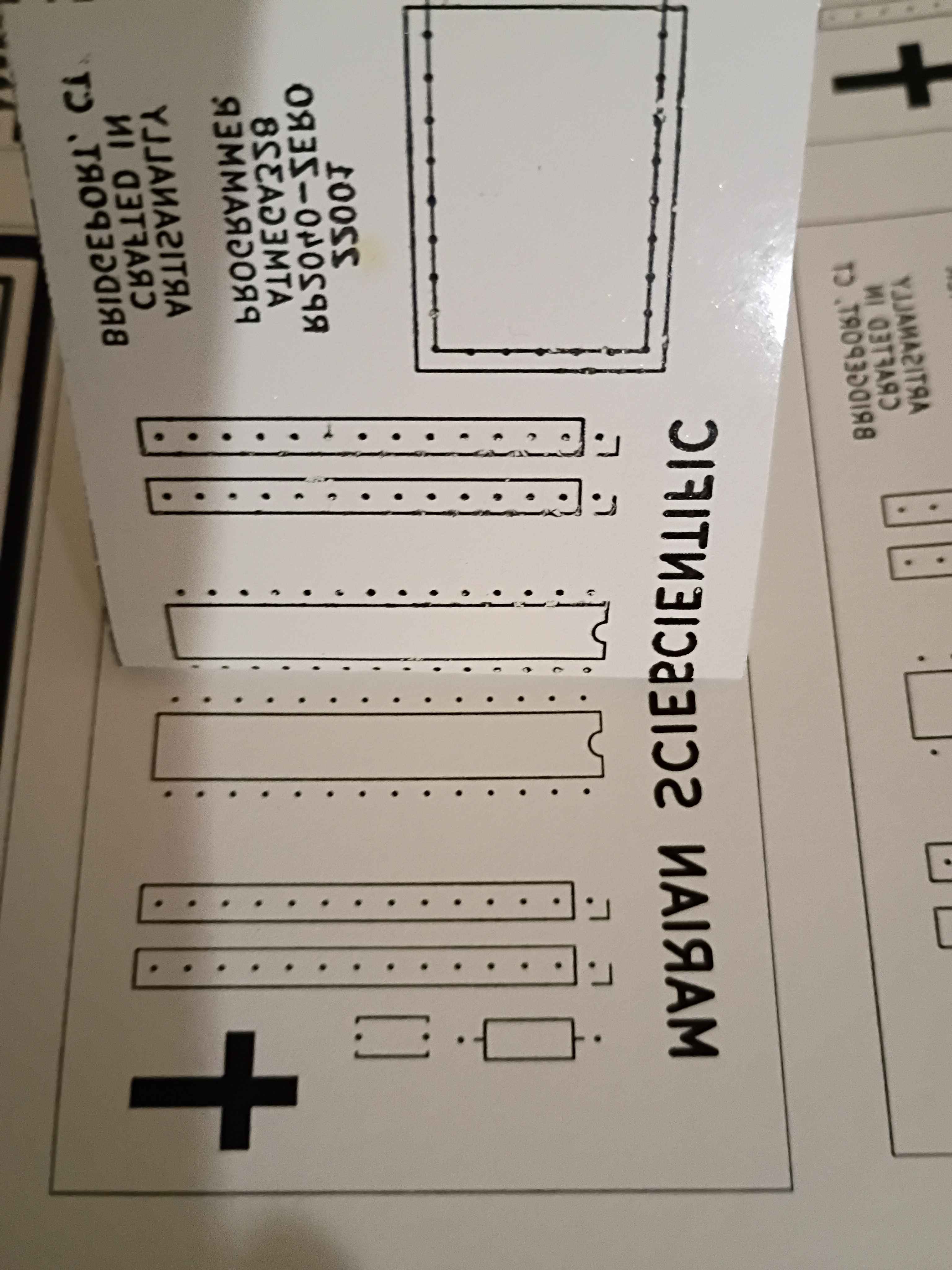
Before I realized I had the sizing wrong, I did retry the toner transfer of the front silkscreen, and it mostly worked, although the cross and some of the letters did not come thru. The areas of toner that didn't transfer properly, I filled in with marker. I can try again with the correct sizing tomorrow, which should help, although the cross probably didn't have enough direct heat applied to it to transfer.
Used Inkscape to put a bunch of the background copper and silkscreen masks onto a single sheet and printed that on glossy paper. 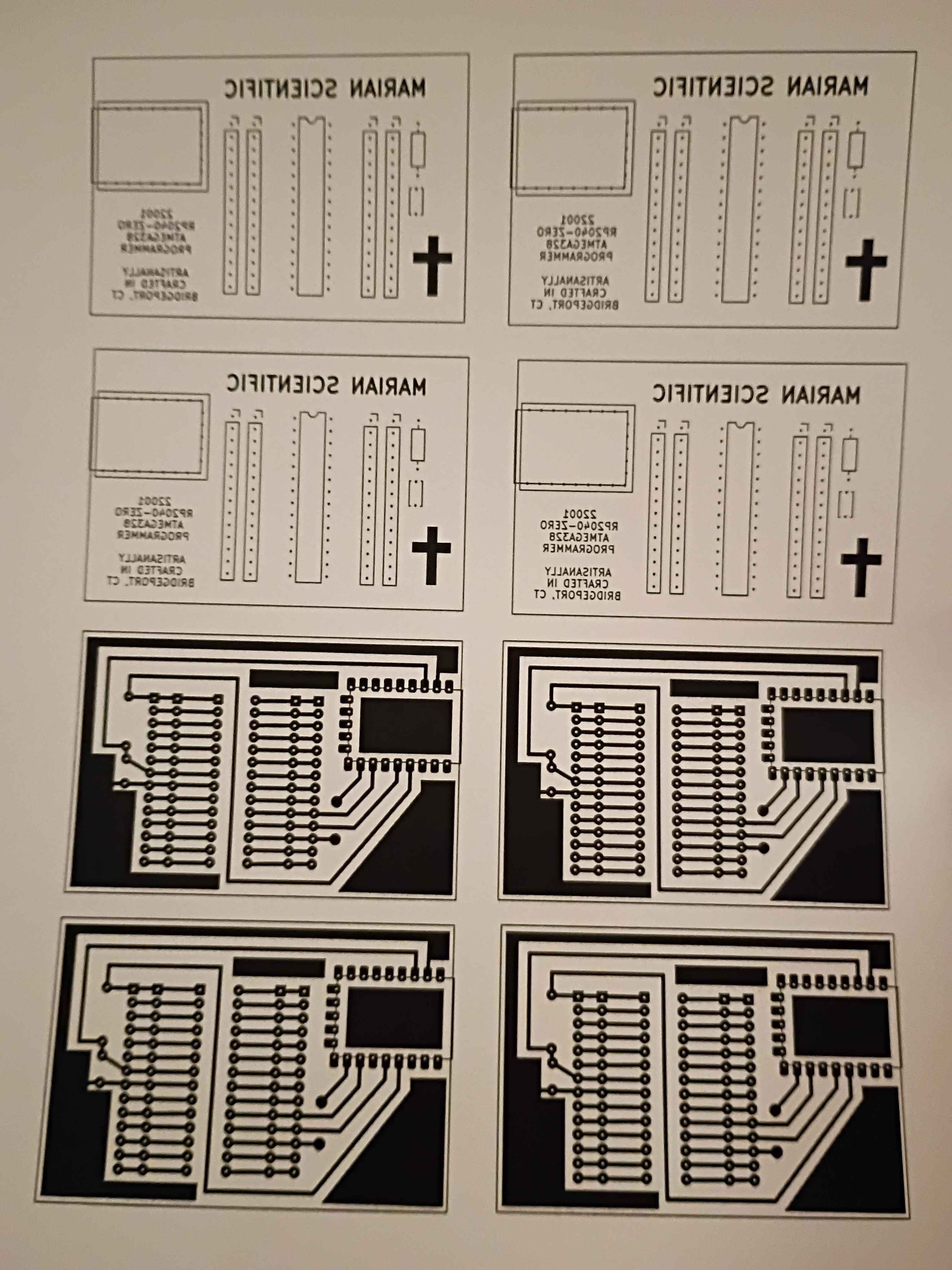
Incorporated a host of improvements to the PCB design of the 12001 RP2040 AVR programmer into a productionized version. See project entry for a list of the improvements and the CAD files. I can begin to fabricate some of these when I get back from my trip.