Designed programmer PCB and attempted to create a DIY PCB at home using etching solution. See video of it in action.
First two attempts were using photoresist, so the mask was negated.
![]()
I didn't have a reliable source of UV, so I used the New England winter sun...
![]()
...which overexposed the photoresist after 10 and even only 5 minutes. Also I had bubbles in the film because I applied it with a clothes iron, whereas a laminator would have done a far better job. In any case, these two attempts failed.
![]()
So I tried the toner-transfer method. I did a much better job of cleaning and scuffing the copper-clad board using 240-grit sandpaper and acetone.
![]()
I printed a non-negated (and unfortunately mirrored, a mistake) plot on glossy paper using a laser toner printer.
![]()
I ironed the paper onto the copper-clad board,
![]()
...and dissolved off the paper over 30 minutes in some warm water. You have to get everything off, even the white paper haze that might find itself between pins and traces that will otherwise prevent the etchant. Noticed I failed to do this on the right, where the RP2040-zero mounts.
![]()
Then I set the board in Ferric Chloride and gently agitated it for 10-15 minutes outside. If I had made most of the board the ground plane, it would have gone a lot faster because less copper would have needed to dissolve away.
![]()
It turned out pretty well, but notice there was still some copper between the pads on the top of the board.
![]()
So I wiped the remaining toner off with acetone and popped some holes in using a very small 0.8mm endmill. In retrospect I should have made the copper pads larger, because I drilled out most of the copper even with my smallest endmill. I also drilled out a hole for the underside of the rp2040-zero board, which although it has castellated edges, cannot be set flat on a board without cutting away the board beneath it. Then I began soldering components. Again, in hindsight, my traces should have been on the opposite side of the board as my components, because they were extremely challenging to solder because the pads were directly beneath. In the future, traces should be on the background copper face if the components will be mounted on the top, and that would not have required that I even mirror the board plot in the first place. I could have also toner-transferred some nice-looking component labels and even a part number if I had set the traces on the opposite side as the components. Either way, this investigation was a learning experience, so I don't mind the soldering challenge and all the other added complexity.
![]()
The photos below show the final product which actually works well as an Atmega328P programmer; I tested several blink programs. The rows of header pins also almost make this into an Arduino-like devboard, though it lacks any external oscillator or other peripherals. I did have to shave down the bottom of my USB-C cable so it could come in flush. A lot about this whole project could be improved significantly, but I had a lot of fun with it. This investigation was a massive success, and we did barely manage to complete it on schedule.
![]()
![]()
![]()
Got the programmer working, which was a combination of the code running on the RP2040 and a Python script transmitting the serial data over USB from my PC. See video.
Wasted ~2 hours today alone tracking down a very dumb mistake - I was off by one on the SPI pins on the Atmega328. No wonder I wasn't getting a response. I completely obliterated the code trying to track it down, so I will reconstitute something clean tomorrow. The AVR chip nonetheless acknowledges our attempts to program it now. ![]()
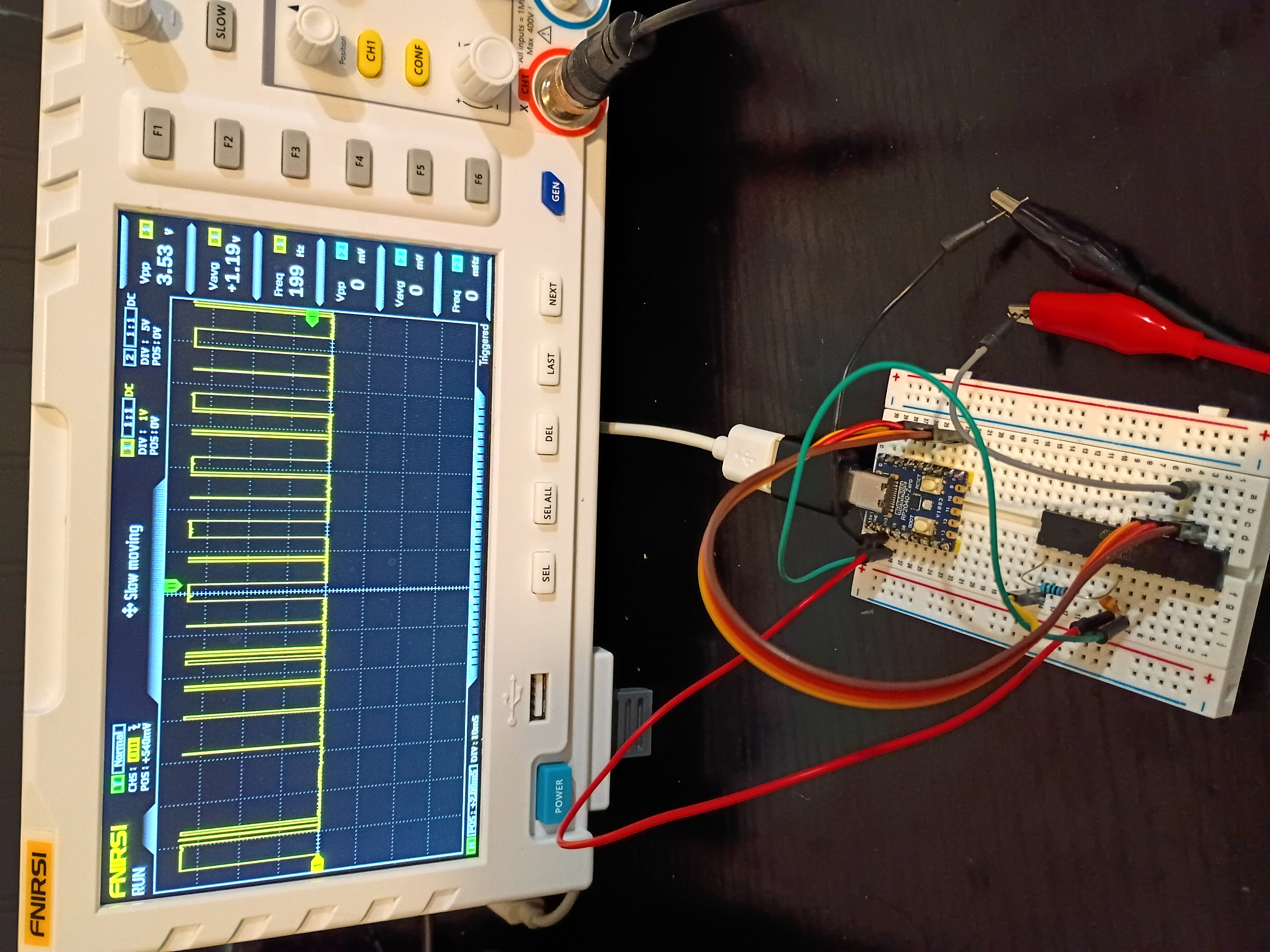
Finished a likely buggy implementation of both the rp2040-USB-programmer and the PC-based hex file transmitter using python. See code directories 005 and 006. The clock and data transmission works as expected, but for some reason the Atmega328P is completely unresponsive; no signal is being transmitted back over MISO. ![]()
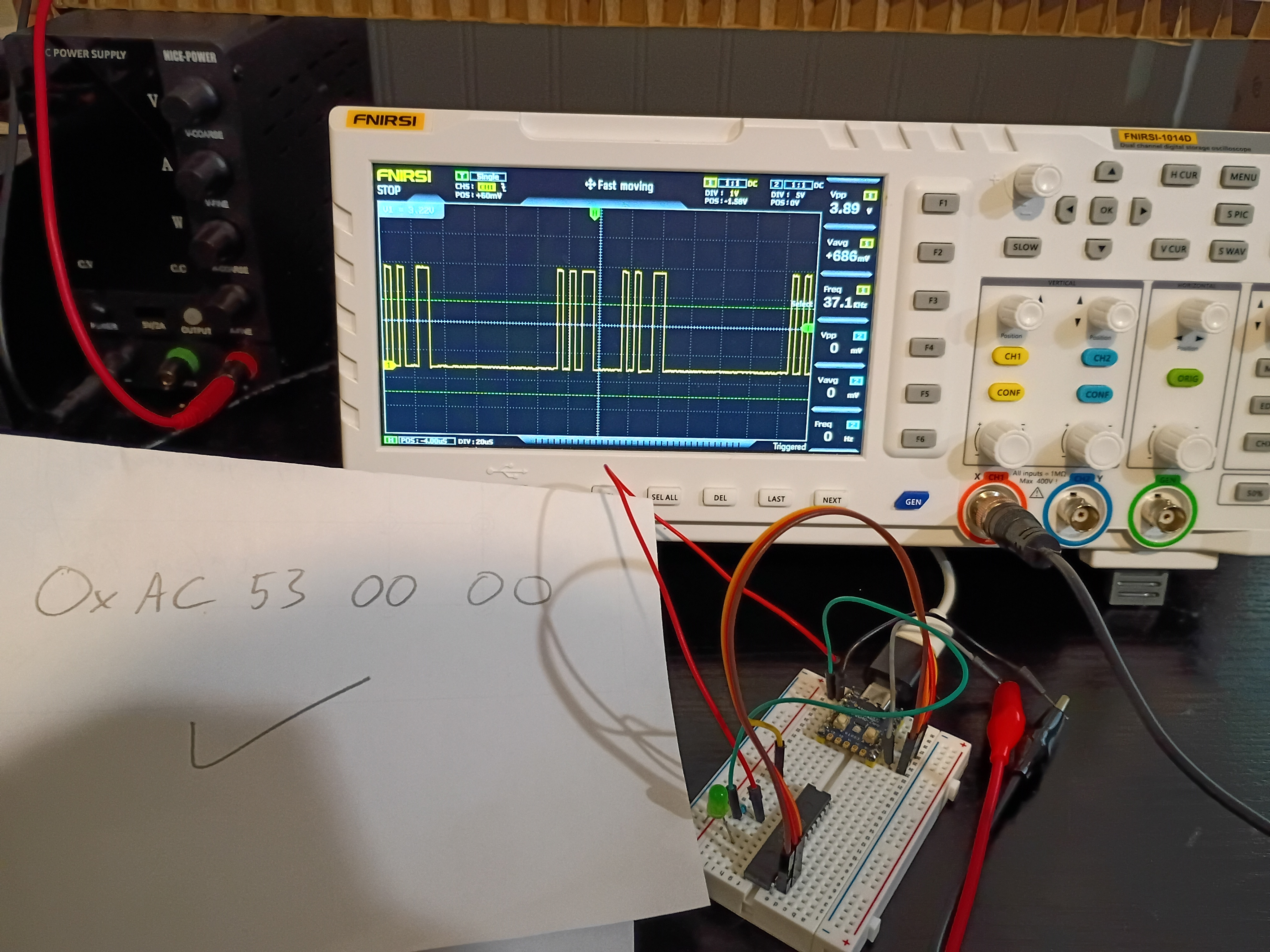
Soldered pins to the RP2040-Zero board for preliminary breadboard tests. Got control of the built-in RGB LED working over PIO (very interesting and powerful) and began working the ICSP algorithm. Link to top-level project directory..
Launched short-term investigation into developing a RP2040-based programmer for AVR ICSP-capable chips, especially the Atmega328P. After internal discussions 2025-12-14, both of these chips seem to be the best avenues for future electronic project development. Completed first three preliminary tasks establishing a functional Atmega328P and RP2040-zero toolchain to complete the remainder of the investigation.