Continued development of Mary-bot. Got the Python bot to more or less successfully run the bash script that regenerates the entire website, though the paths need to be updated for the links and the image references. Still not yet ready for full journal submission migration.
Continued development of Mary-Bot. It now can automatically name images entries. All the user needs to do is type [IMG] in the corresponding place in their text content. Not yet ready for full journal submission migration. I'd like to put in the ability to edit entries thru Discord commands as well.
Continued development of Mary-Bot. She can now track and edit the project list thru Discord commands and populate a new journal .ini automatically along with uploading a set of image files. Another day of work will be required.
Set up VPS with https and attached it to the marian-scientific.org domain. Set up the preliminaries of Mary-Bot, a Discord bot that will automatically push journal entries to the site. Another day or so of work will be required.
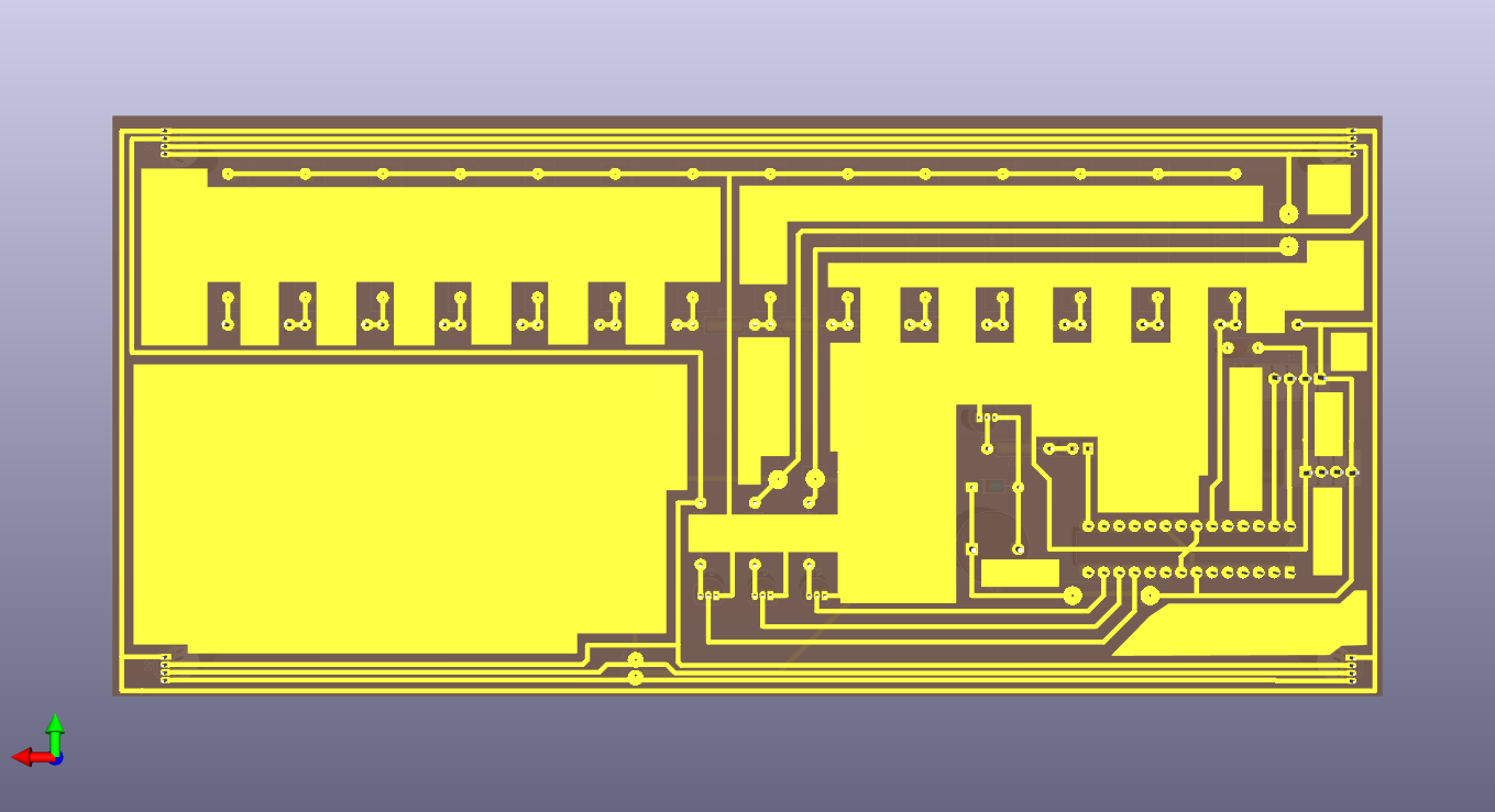
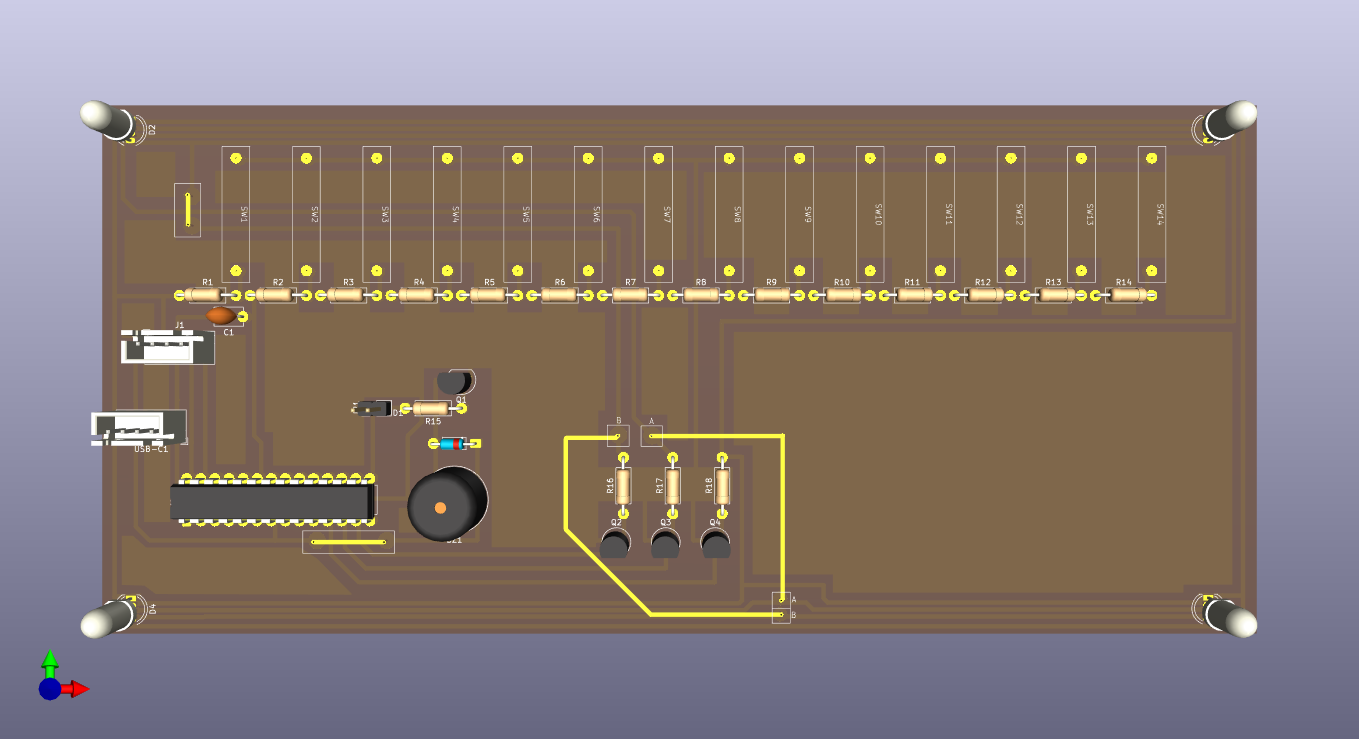
Updated draft schematic and created PCB design for the main control board using the latest PCB-etching lessons learned. This board will be fabricated in-house. See 03010-002 Kicad project.
Created draft schematic for the main control board. See 03010-002 Kicad project. 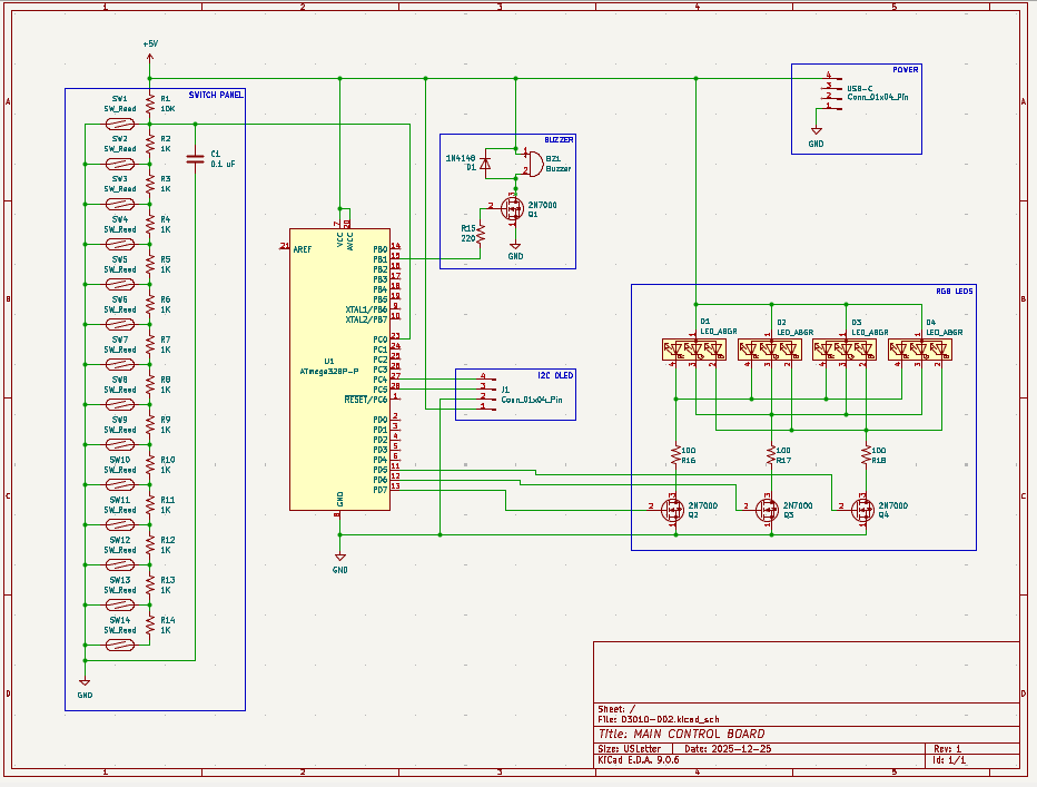
Created SVG for laser cutting & engraving simplified ruler. See project CAD directory. 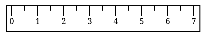
Incorporated a host of improvements to the PCB design of the 12001 RP2040 AVR programmer into a productionized version. See project entry for a list of the improvements and the CAD files. I can begin to fabricate some of these when I get back from my trip.
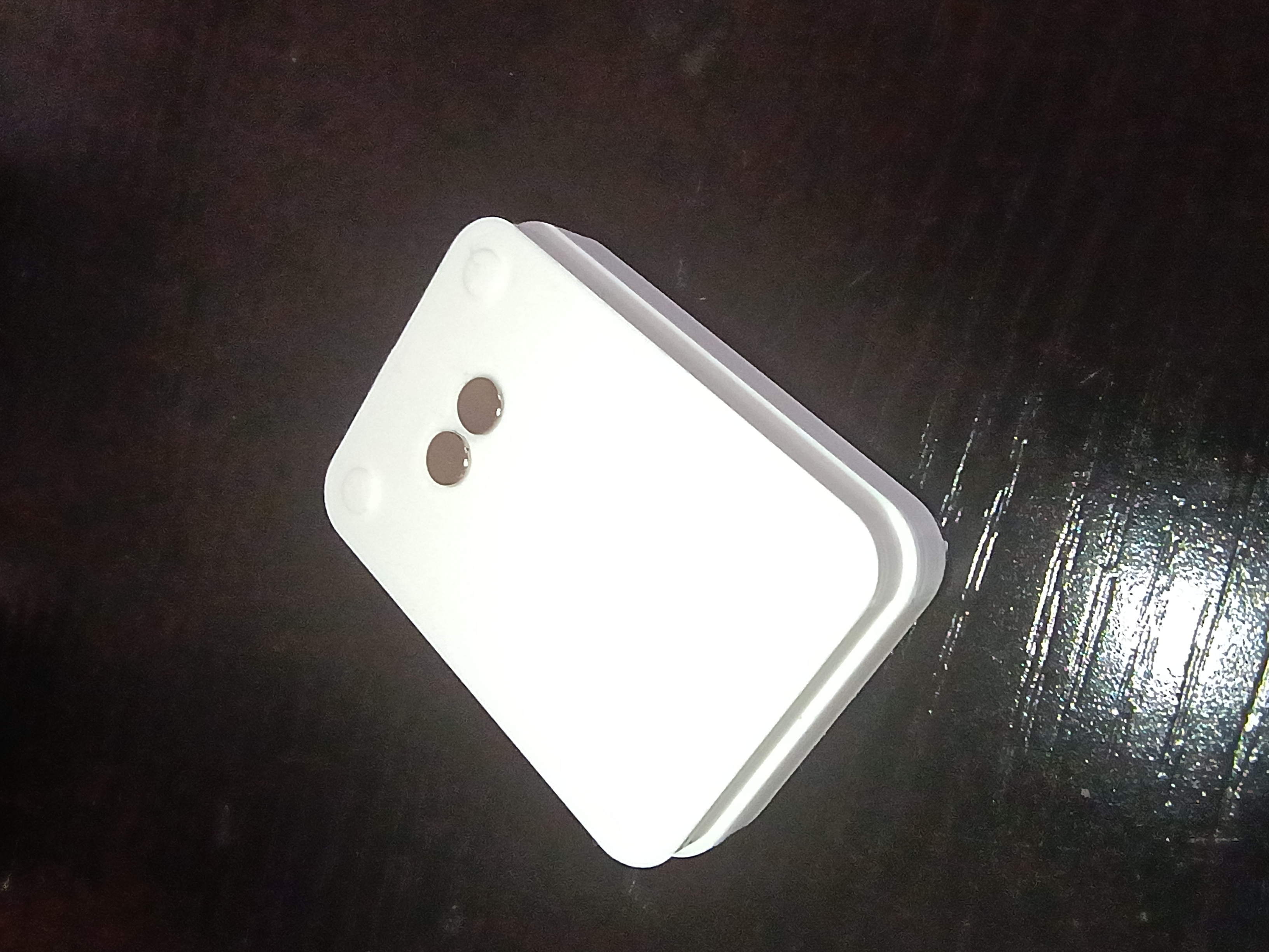
After brainstorming follow-on math manipulatives with the client, we are launching a prototype effort for a manipulative involving ruler measurements. As was learned on xMM1, moving parts and a tactile input device make the manipulative very engaging for the children. This manipulative will consist of a box with an exposed sliding piece of plastic that the children will need to measure. The plastic slide will be connected to a rack and pinion so it can be driven by a servo to expose different lengths of plastic to be measured. The children will need to place a ruler against the box, and to make sure they line up the ruler correctly with the start of the plastic slide, there will be a reed switch that detects that and shows a green status LED. When the measurement is made, the child will be able to select the value (in half-inch increments) using a pegboard, by putting a peg with a magnet into the corresponding marked circular slot. The different values can be connected to a series of resistors to be able to detect the voltage value with a single ADC pin, versus having to waste a lot of GPIO pins. If the rack and pinion approach does not work due to space limitations, a servo-controlled paper scroll can be used instead.
Yesterday, I programmed another stm32 bluepill and I added a Logic Leveler from 3.3V to 5V.
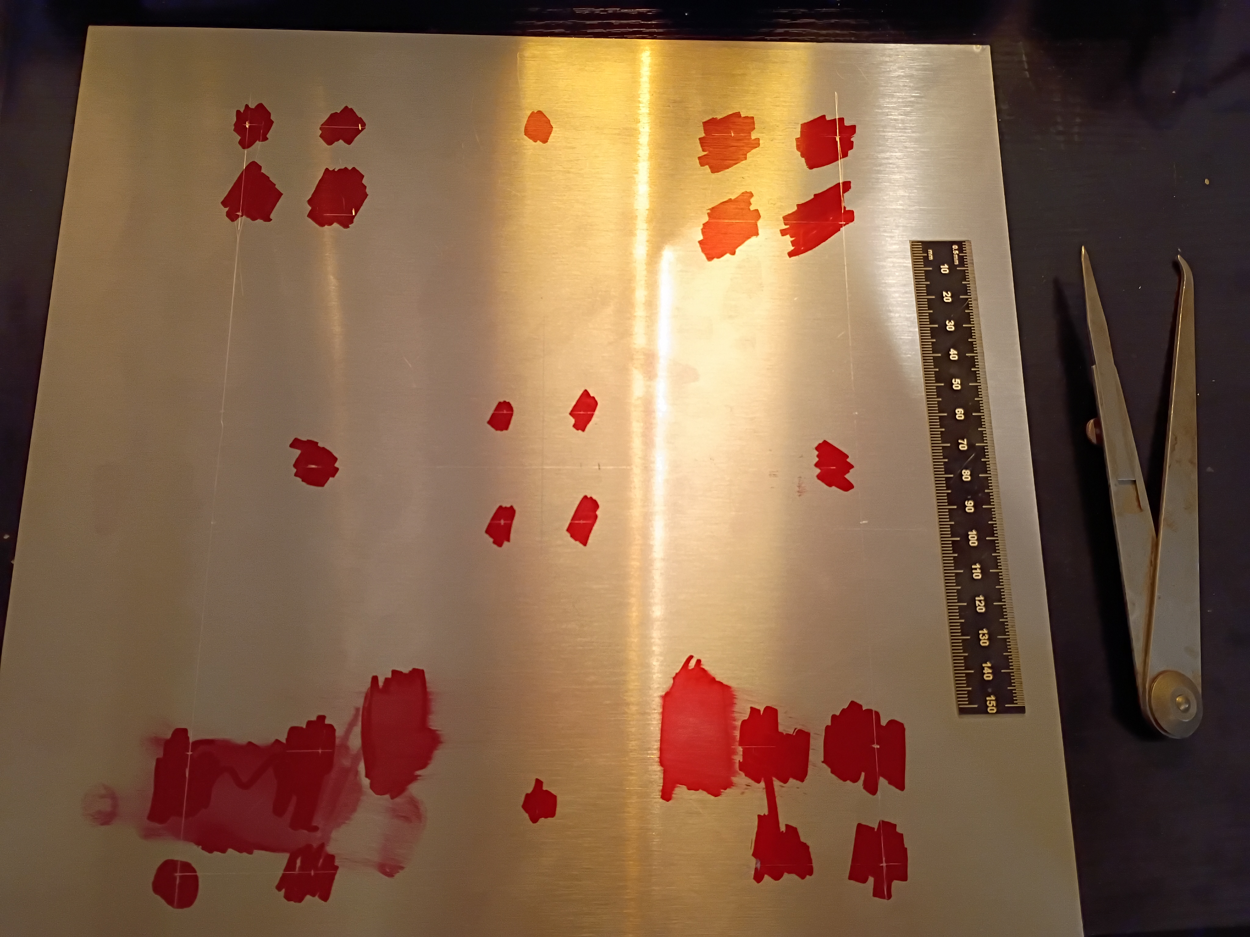
Designed programmer PCB and attempted to create a DIY PCB at home using etching solution. See video of it in action. The photos below show the final product which actually works well as an Atmega328P programmer; I tested several blink programs. The rows of header pins also almost make this into an Arduino-like devboard, though it lacks any external oscillator or other peripherals. I did have to shave down the bottom of my USB-C cable so it could come in flush. A lot about this whole project could be improved significantly, but I had a lot of fun with it. This investigation was a massive success, and we did barely manage to complete it on schedule
Got the programmer working, which was a combination of the code running on the RP2040 and a Python script transmitting the serial data over USB from my PC. See video.
Wasted ~2 hours today alone tracking down a very dumb mistake - I was off by one on the SPI pins on the Atmega328. No wonder I wasn't getting a response. I completely obliterated the code trying to track it down, so I will reconstitute something clean tomorrow. The AVR chip nonetheless acknowledges our attempts to program it now. 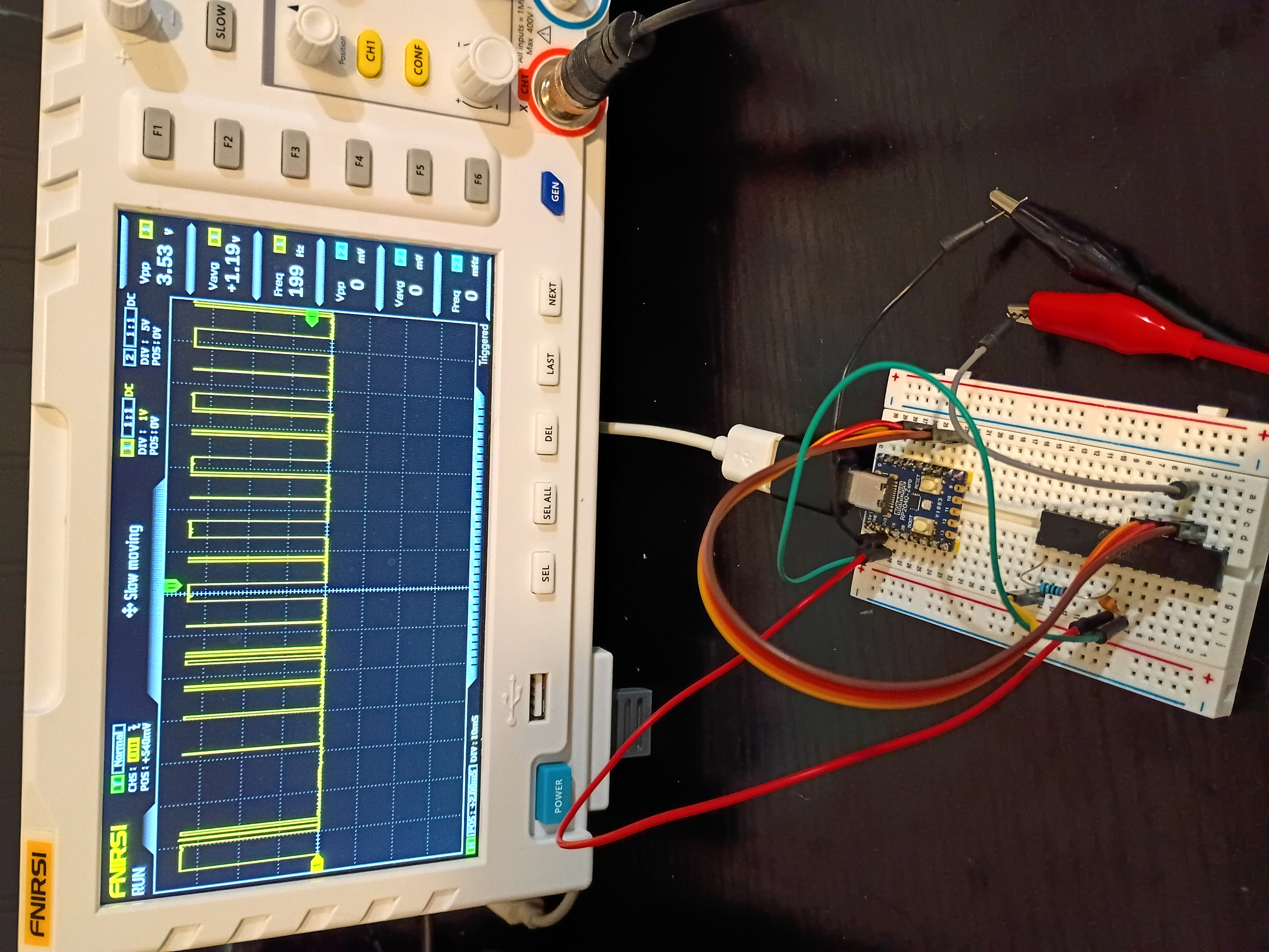
Yesterday, When the Mounted seven segment displays arrived, I realized I has a little problem. This is a front that was designed by myself for MM1 Minute hand.
Finished a likely buggy implementation of both the rp2040-USB-programmer and the PC-based hex file transmitter using python. See code directories 005 and 006. The clock and data transmission works as expected, but for some reason the Atmega328P is completely unresponsive; no signal is being transmitted back over MISO. 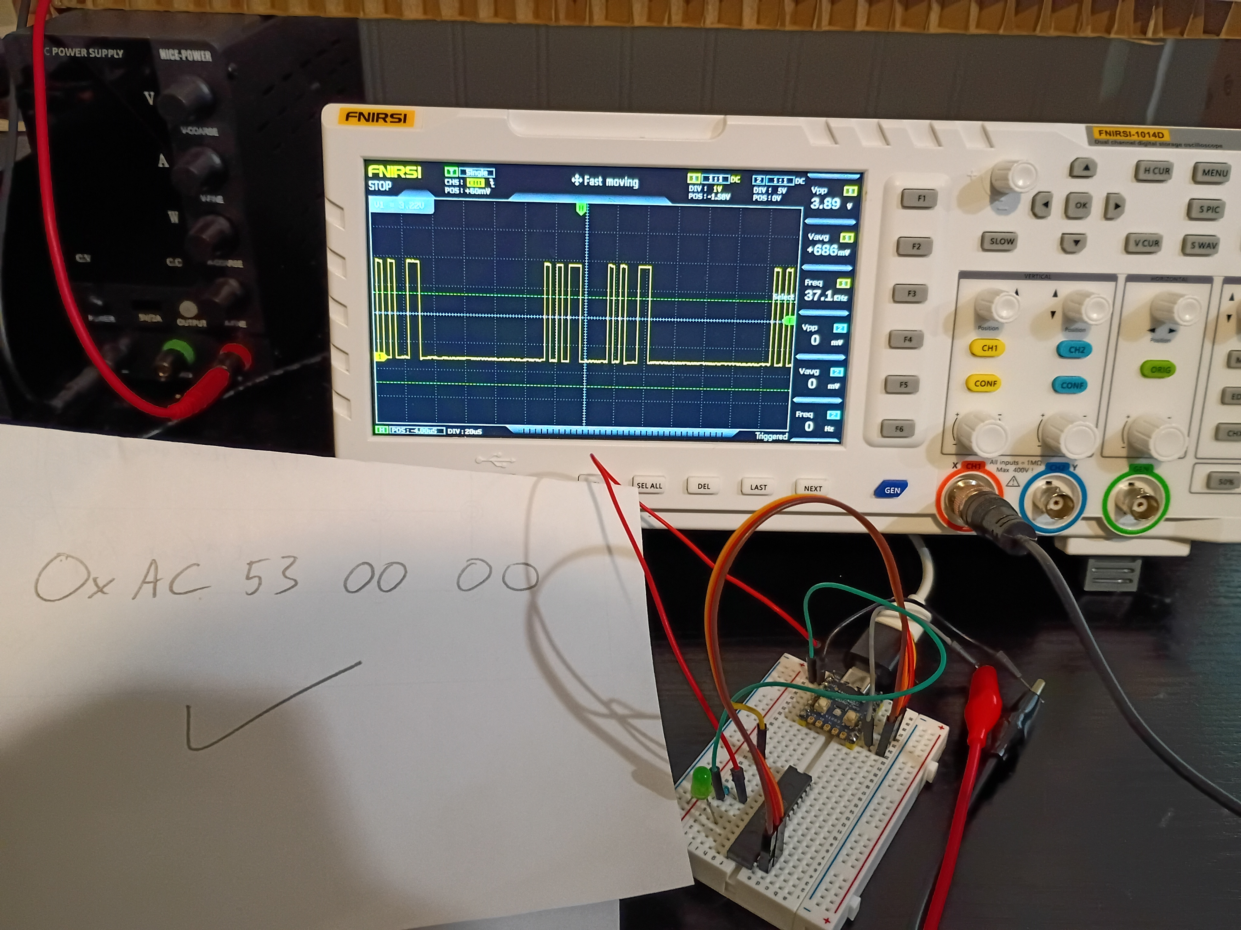
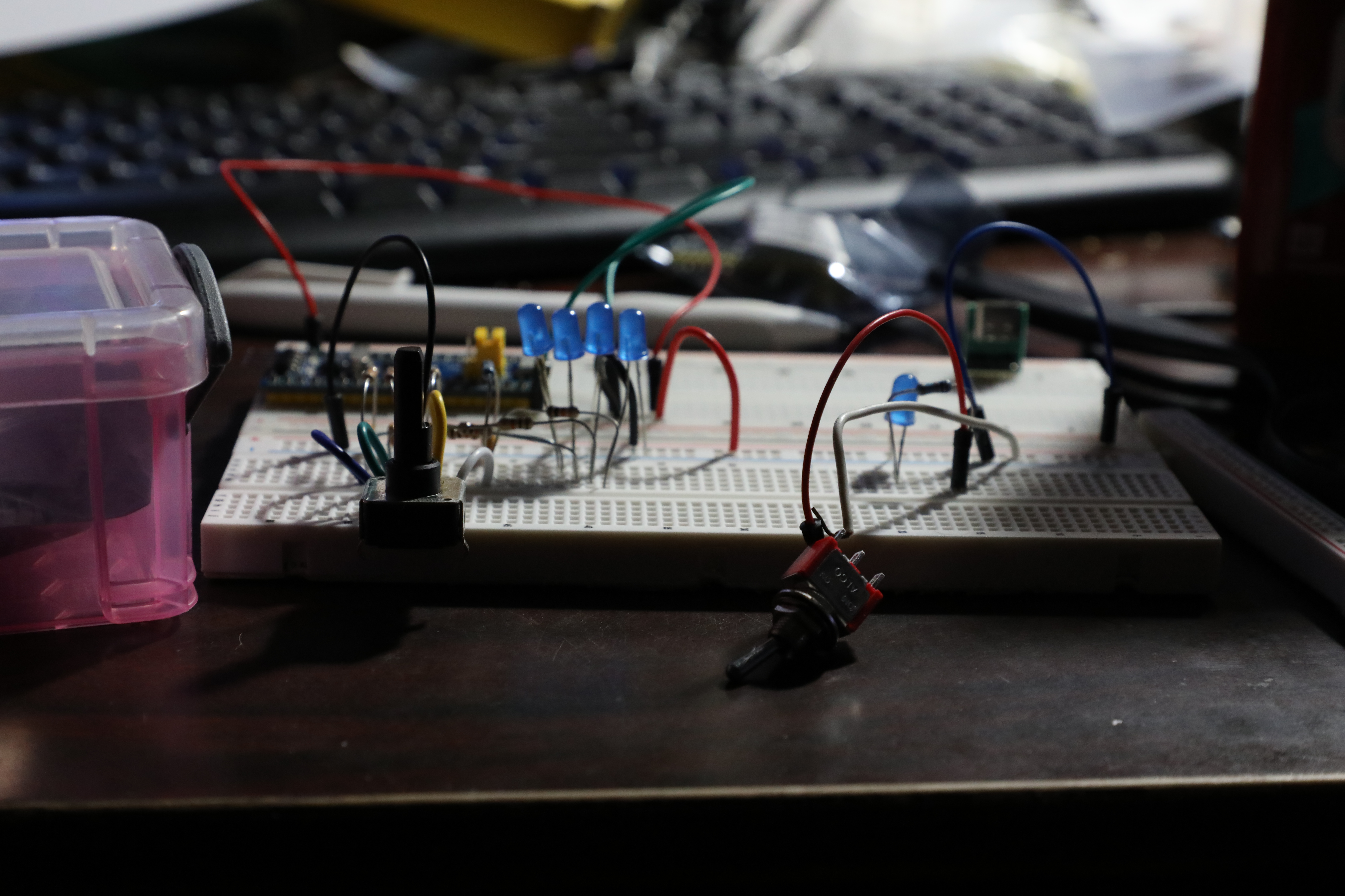
A few days ago, there was a lot of work done. The circuit was constructed on a breadboard. 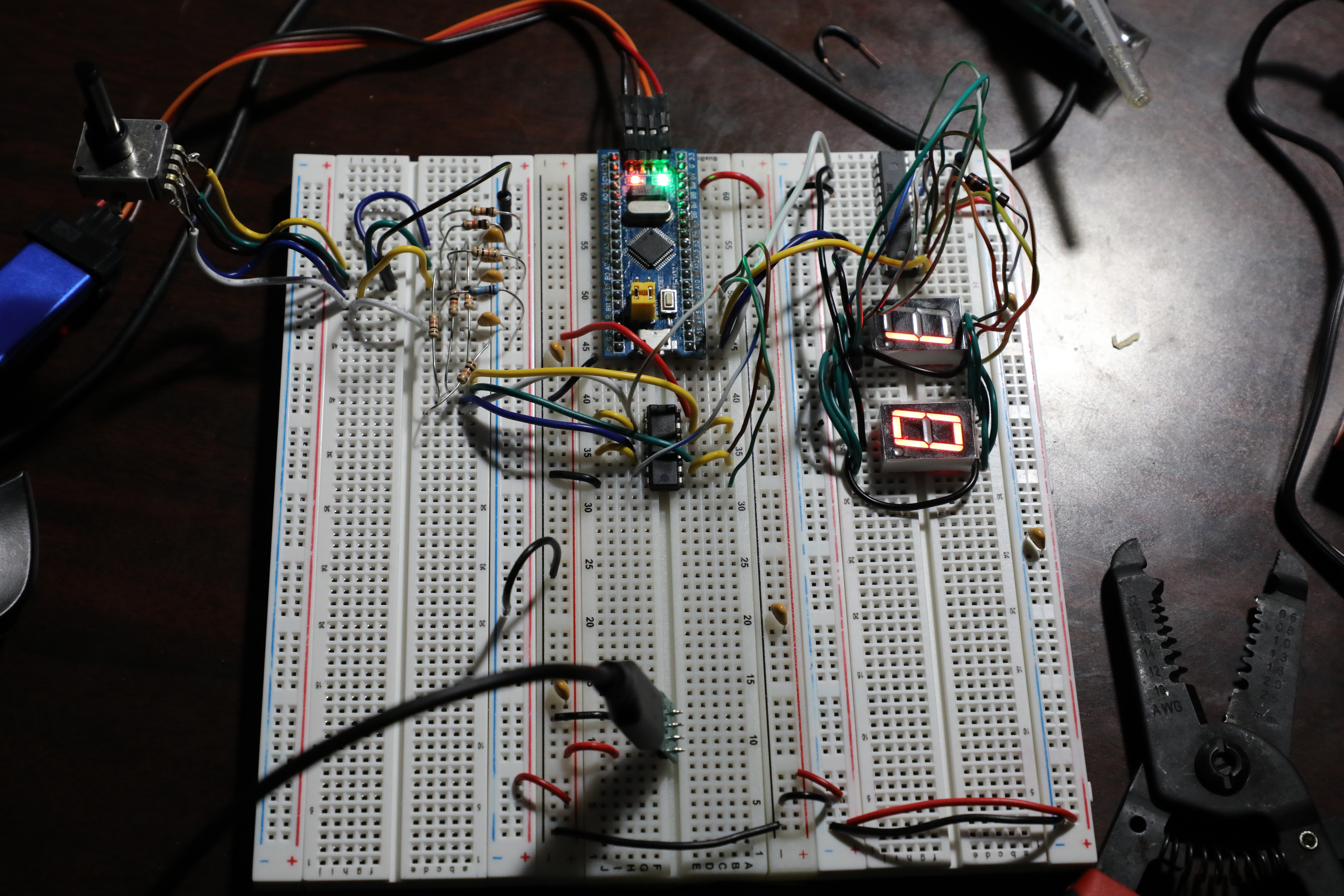
Soldered pins to the RP2040-Zero board for preliminary breadboard tests. Got control of the built-in RGB LED working over PIO (very interesting and powerful) and began working the ICSP algorithm. Link to top-level project directory.
Launched short-term investigation into developing a RP2040-based programmer for AVR ICSP-capable chips, especially the Atmega328P. After internal discussions 2025-12-14, both of these chips seem to be the best avenues for future electronic project development. Completed first three preliminary tasks establishing a functional Atmega328P and RP2040-zero toolchain to complete the remainder of the investigation.
Received 6 of 6 (no extras) 03007-001 stepper coil-driver PCBs from OSH Park. They arrived in 15 days. The communication from the company was far better than DKRed. The board quality is decent, and the price is comparable. Boards (purple cheapest and default option) do come with jagged edges where they are broken from a larger PCB platter. I do prefer them to DKRed. 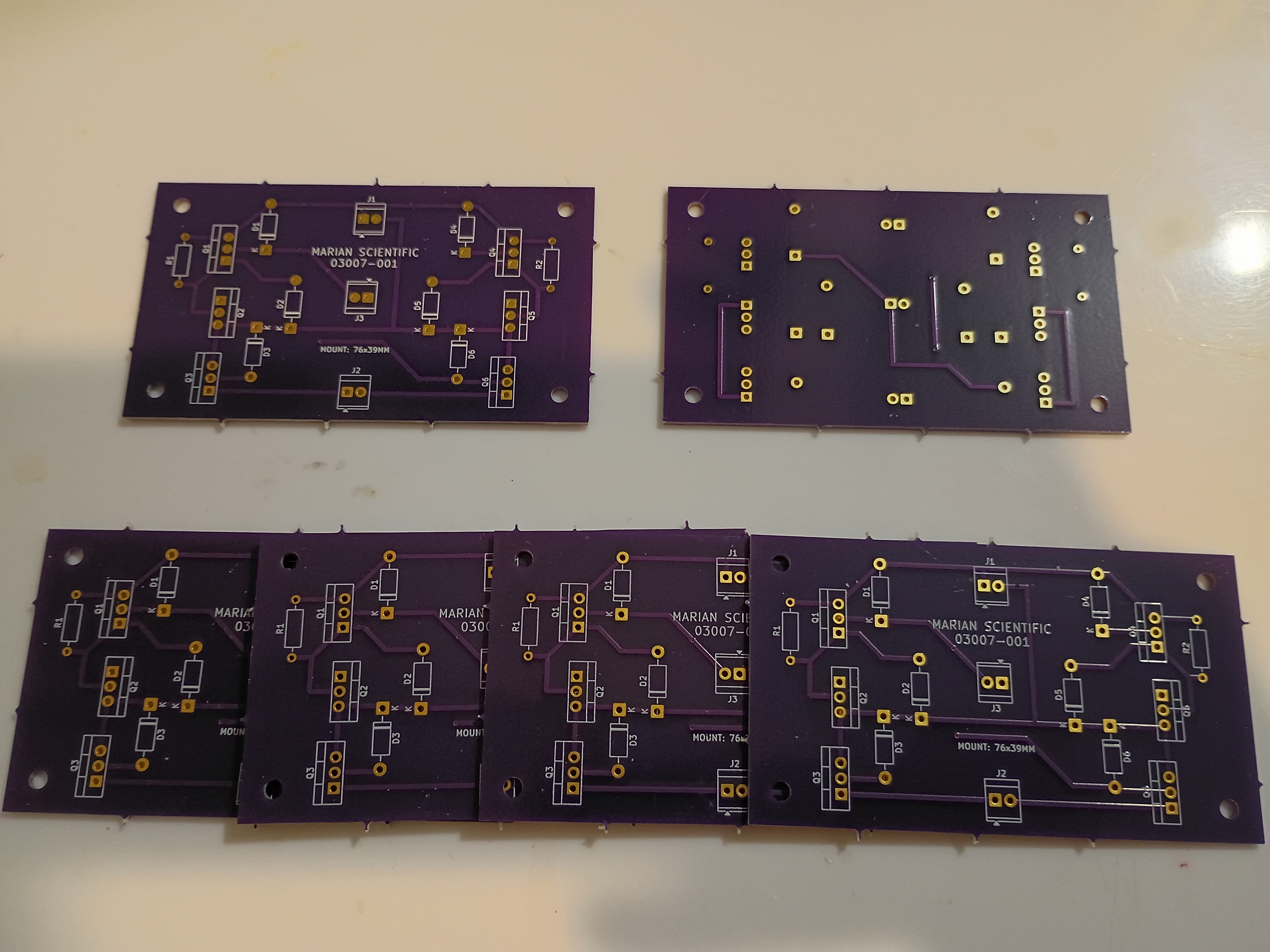
Recorded final video of manipulative working. The prototype will be used as a template for a future productionization effort and, afterwards, permanently donated to the test classroom.
Tested the project with 6-7 year olds, and it was a massive hit. Kids were fighting over the 3 magnetic input blocks, and I kept a half-dozen or so busy for around 15 minutes during dismissal. They thought it was professionally-made. I think one factor about the manipulative that they enjoyed was the tactile nature, which is not something familiar to them in an age of touchscreen-everything. 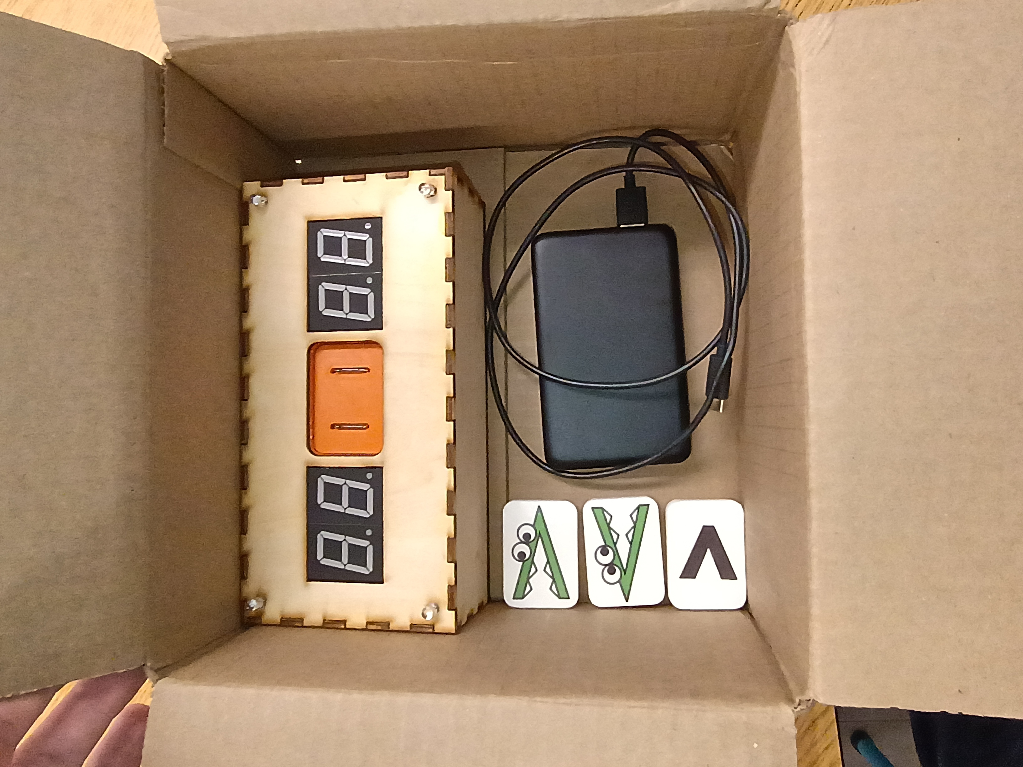
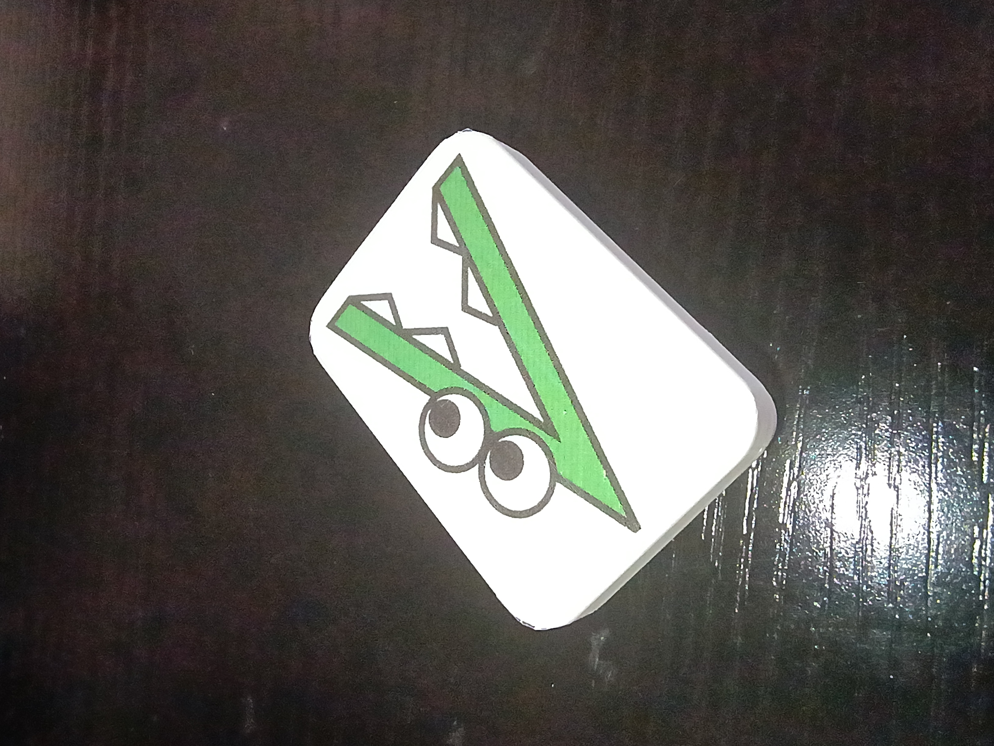
Project complete 3 days early. Made final updates to the full project code to fix the RNG and the intermittent failed 7-segment initialization. Also somehow the power draw is now high enough that it doesn't seem to automatically shut off the USB power bank, though the power bank still reads 100% after 3 days of testing. Designed a new 03008-010 input block with standoffs and a bigger grip area. See latest CAD. Printed two versions in new white PLA and applied the 'Alligreater' image (one mirrored) to the front with a glossy transparent parent sticker. Will test this device with the children tomorrow. 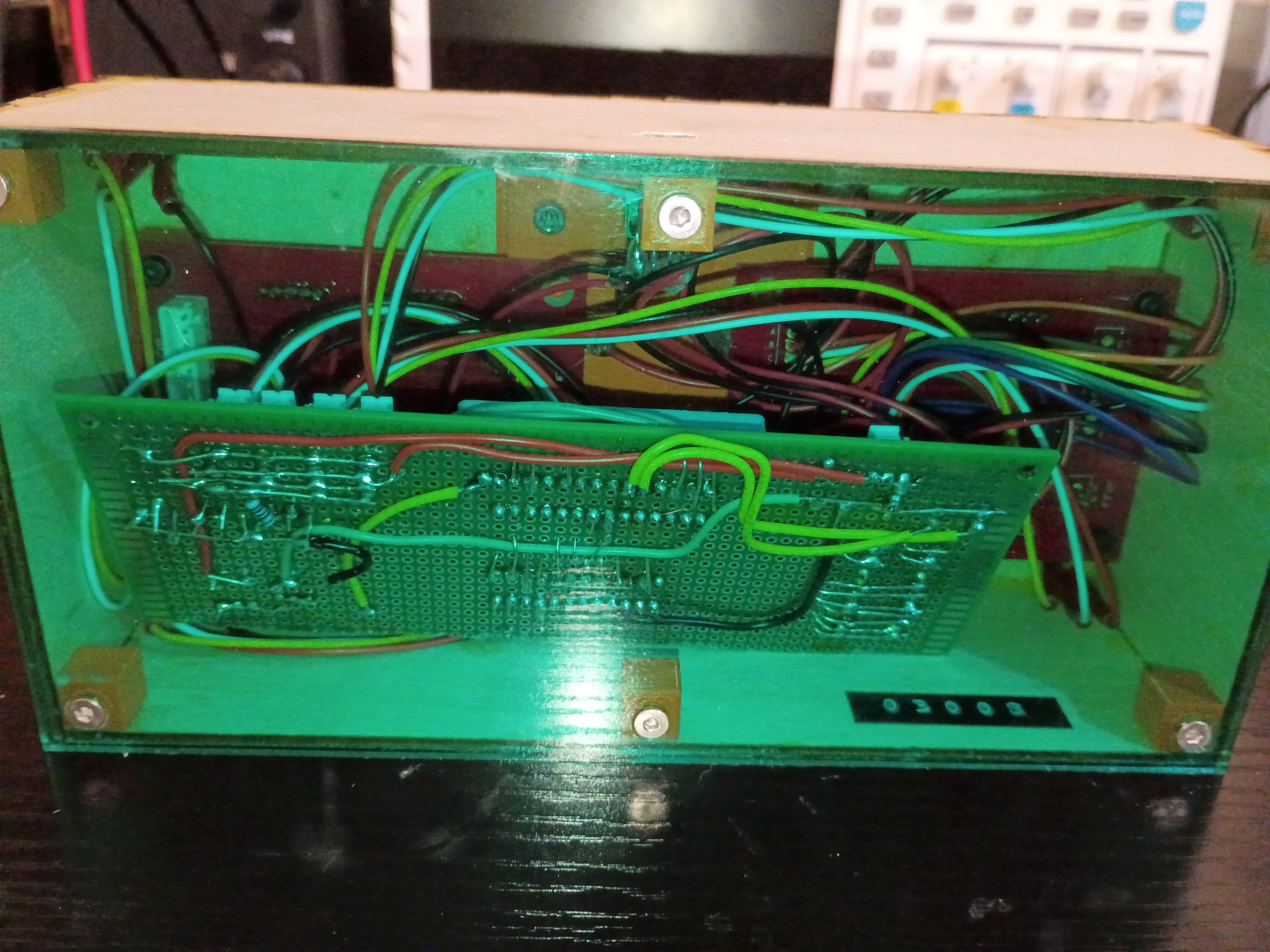
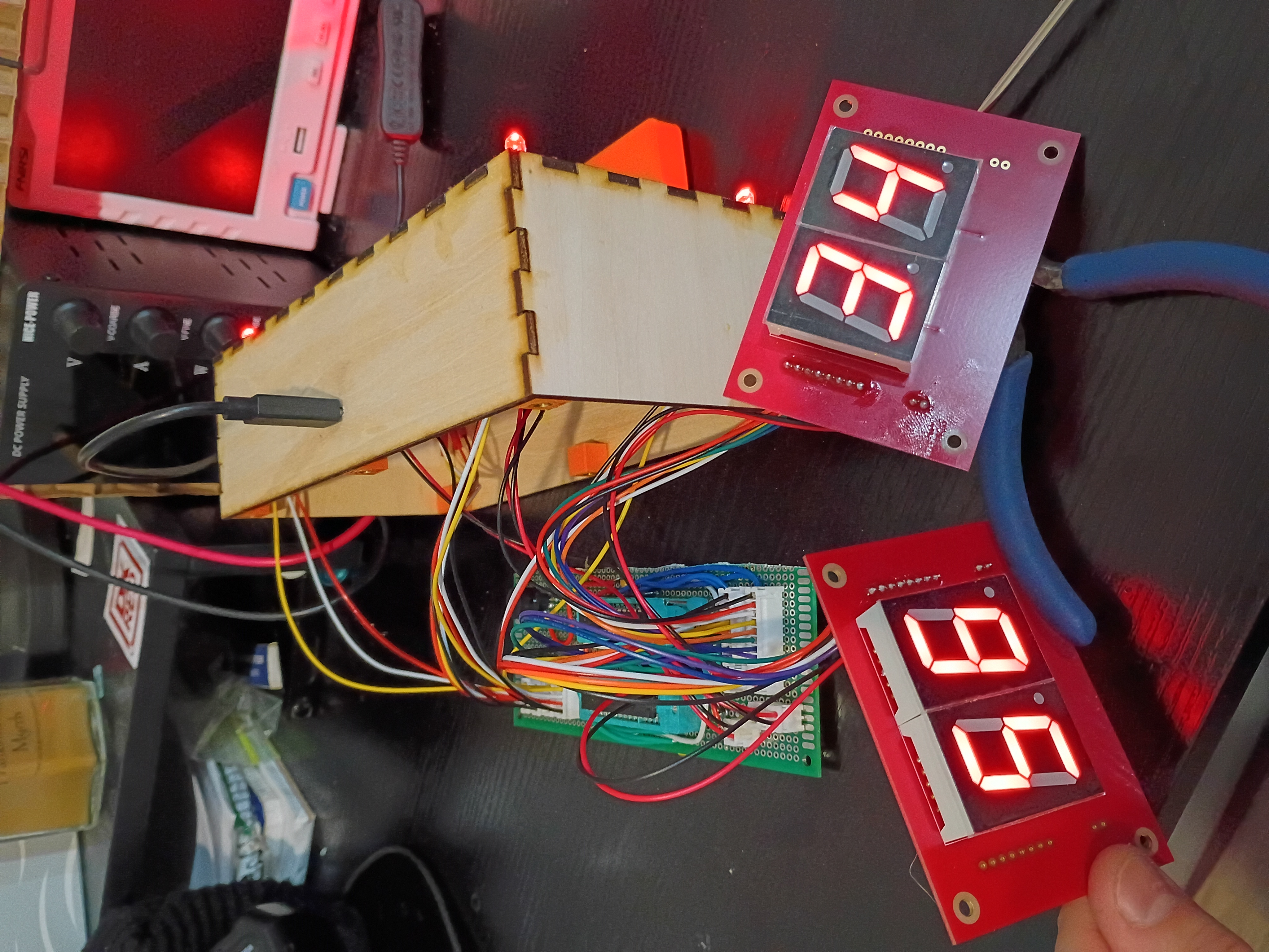
Updated the full project code. Entire project essentially works - including the buzzer, RNG, LEDs, magnetic inputs, etc. See video of it in action. Still needs an improved input block and there is still a glitch where it sometimes initializes with 88/88 on the displays.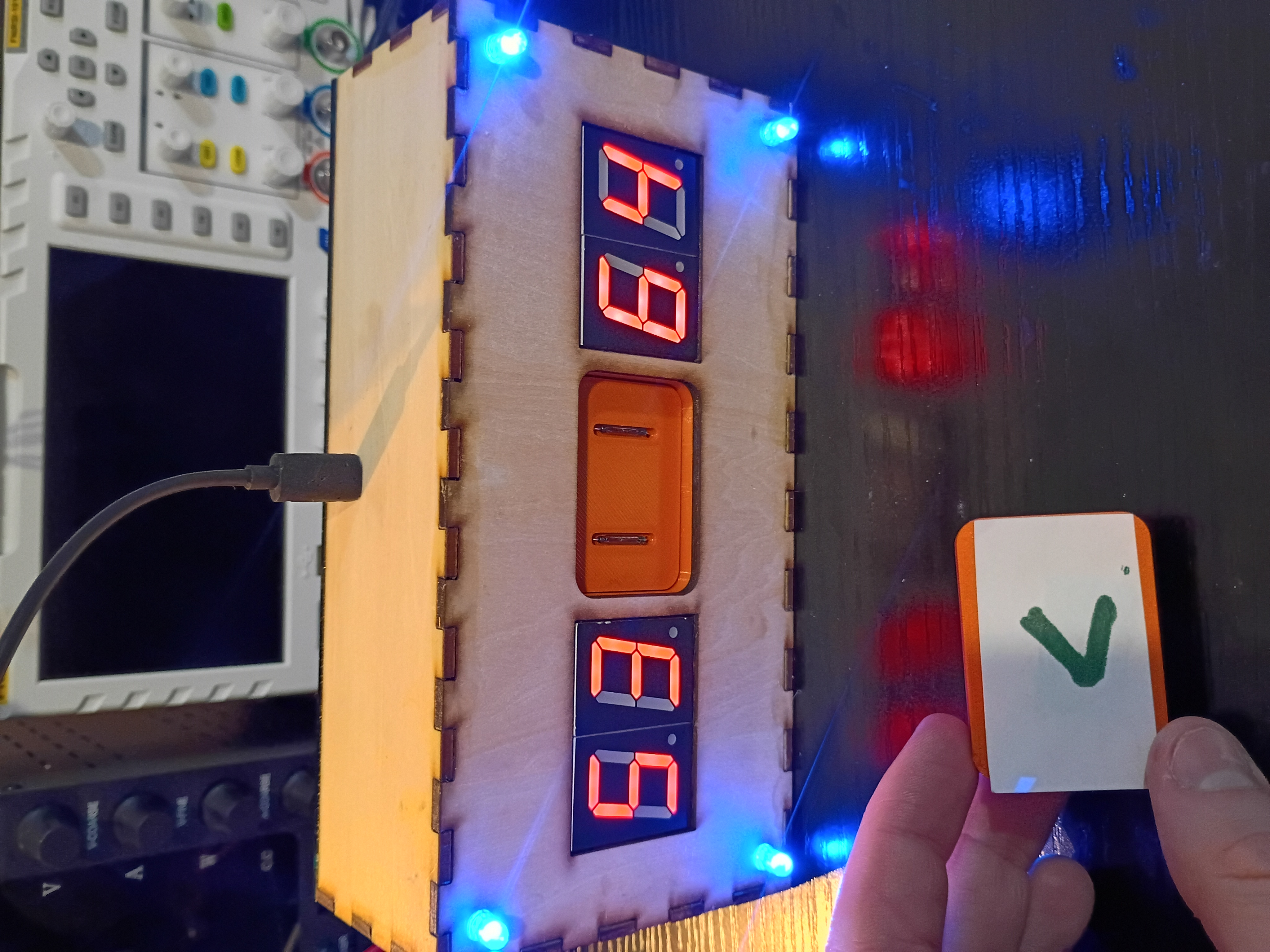
Toyed around with the code for a while, but there is something amiss with the buzzer control timer and the rest of the control logic, so I implemented a buzzer-less version. Had to improve the solder connections, but everything fits in the box pretty well. Needs to be cleaned up slightly. See video of it in action. 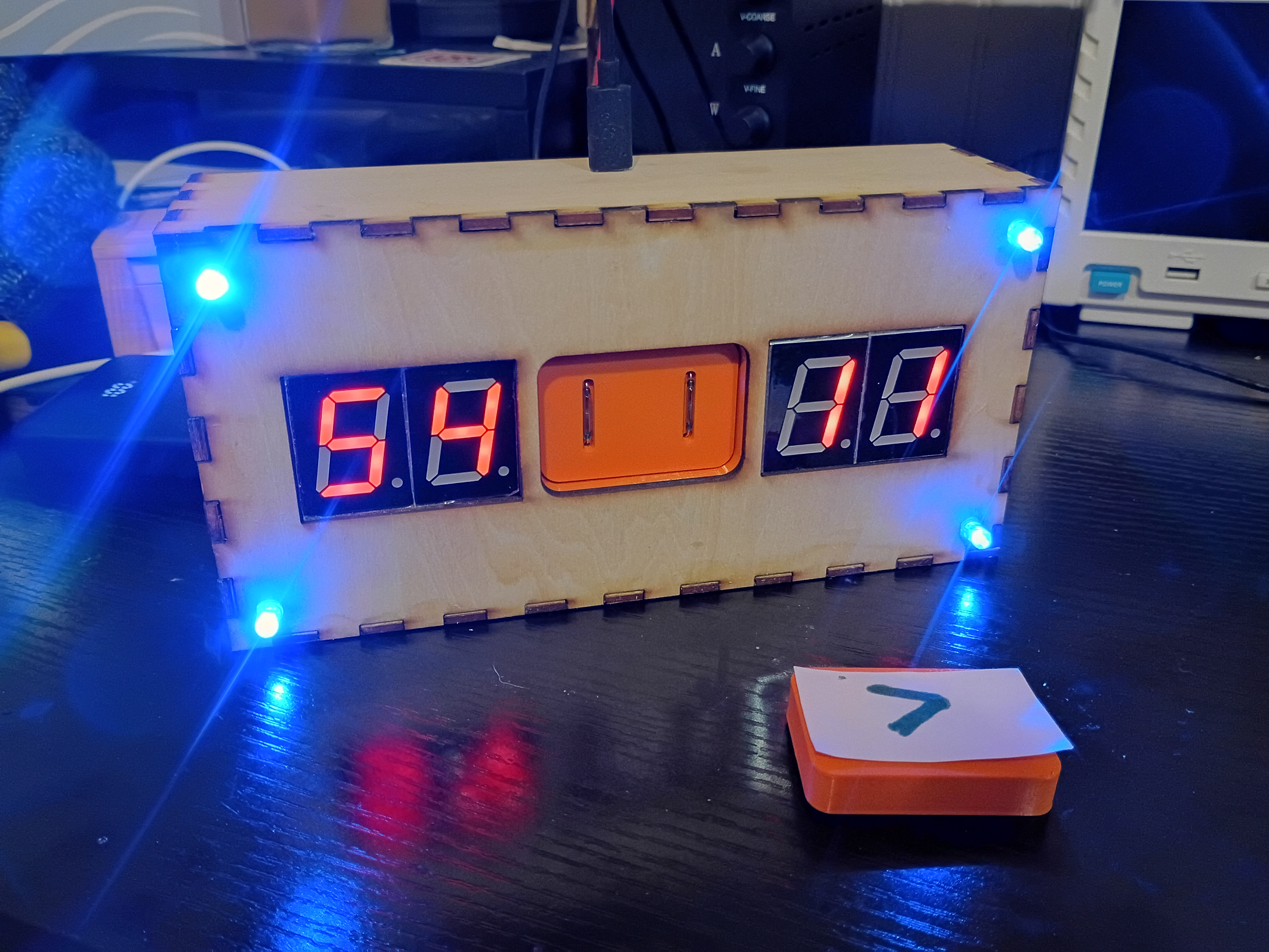
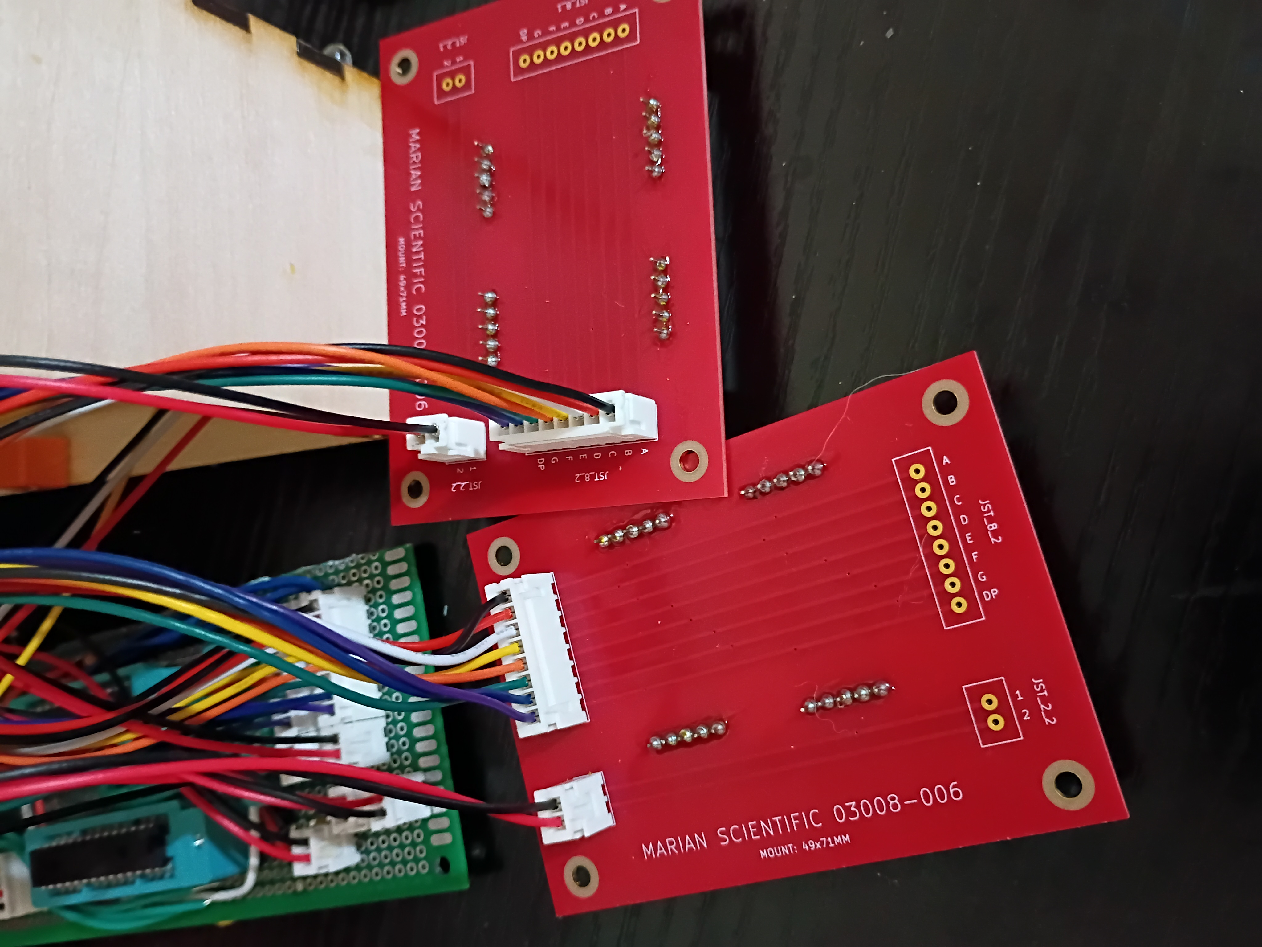
After 2.5 weeks, received 03008-006 PCBs from DKRed. Board quality very good, no mistakes were made on my end or theirs. Silkscreen font kind of squiggly in places. Overall experience was positive, though very slow. They sent 2 extra boards (6 instead of 4). Should probably make the thru holes slightly larger next time. Soldered 7-segments and JST connectors to the PCB and tested some sample code to display digits. There is some software/hardware glitch that is interfering with the buzzer and LEDs. Also, had to hand-crimp the individual JST metal pins to each wire using needle-nose pliers, as the junky JST crimpers I purchased are terrible. I also prepared two additional boards to be shipped out to support the 03009 project. 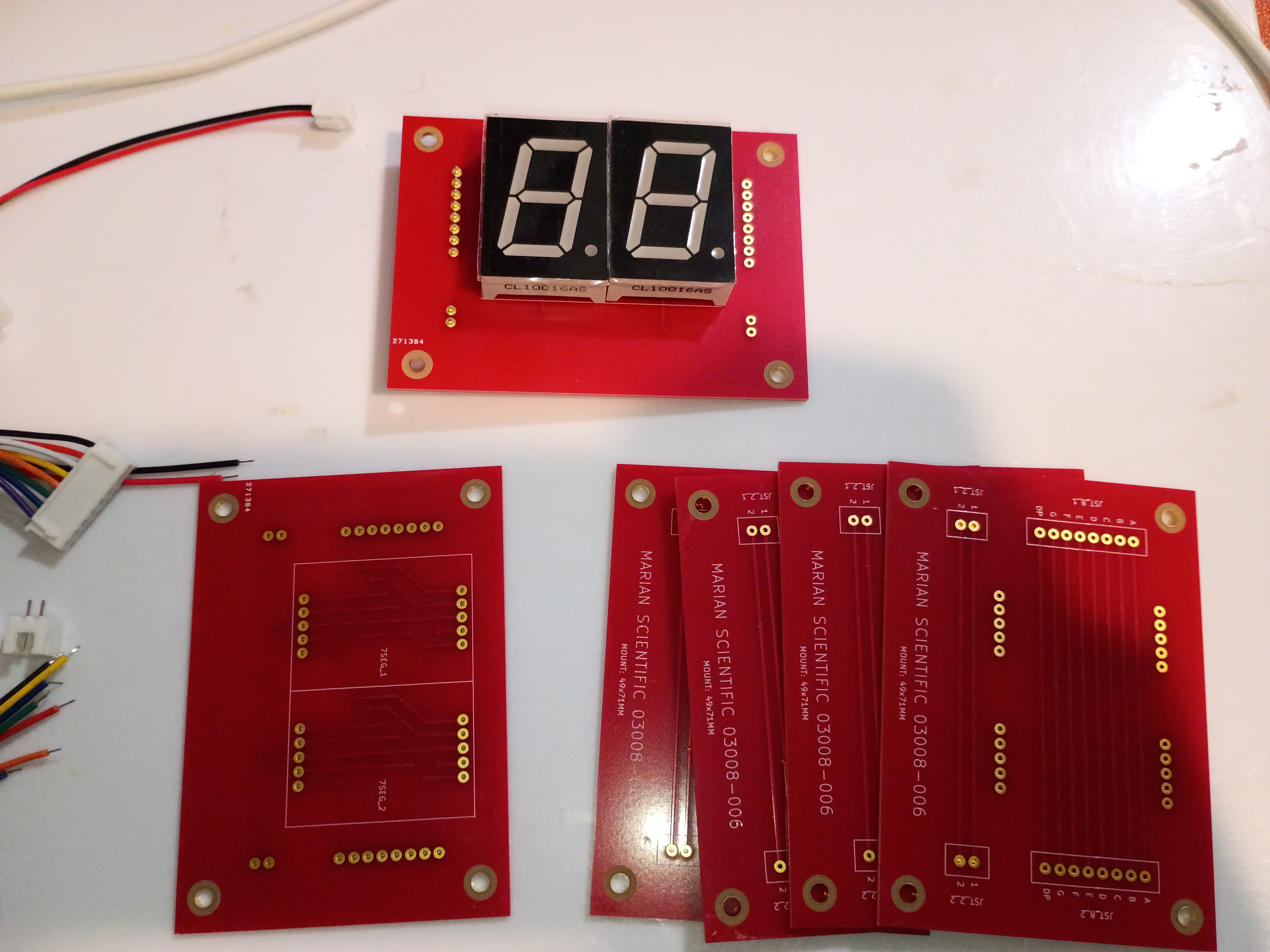
Behold a rasterized version of my 'Alligreater' SVG to be either laser engraved cut or printed/laminated/pasted to the front of the magnet block. 
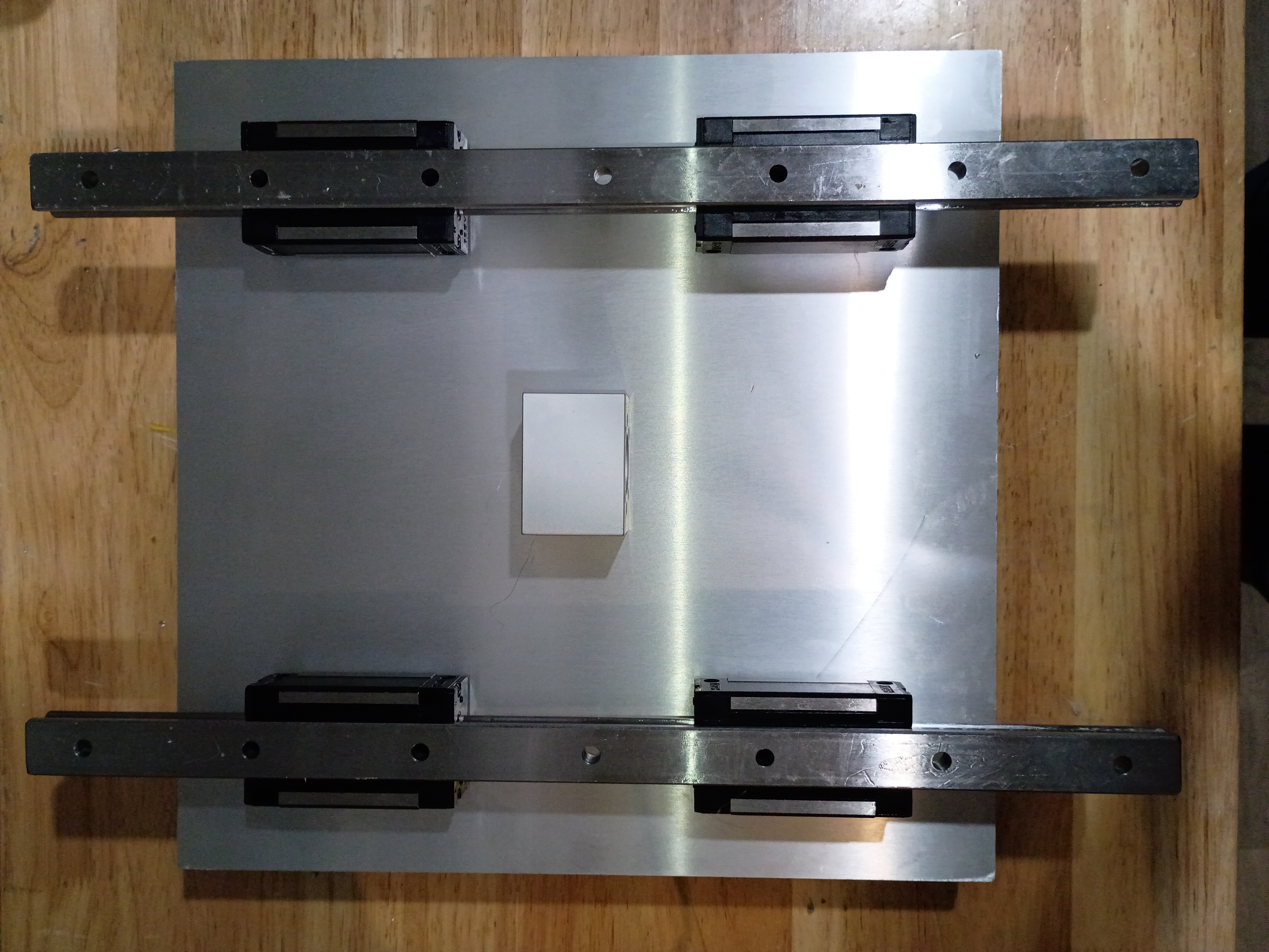
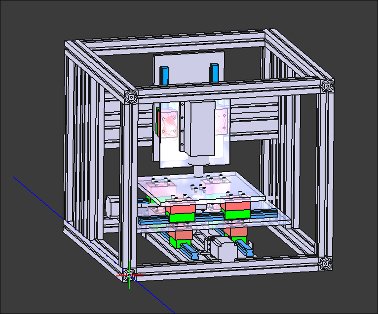
Put final counterbores into X-Y gantry plate and test-fit the linear rails and ballscrew ball nut carriage block. Somehow miraculously everything is aligned. I do still need to put in tapped M5 mounting holes for attaching things. 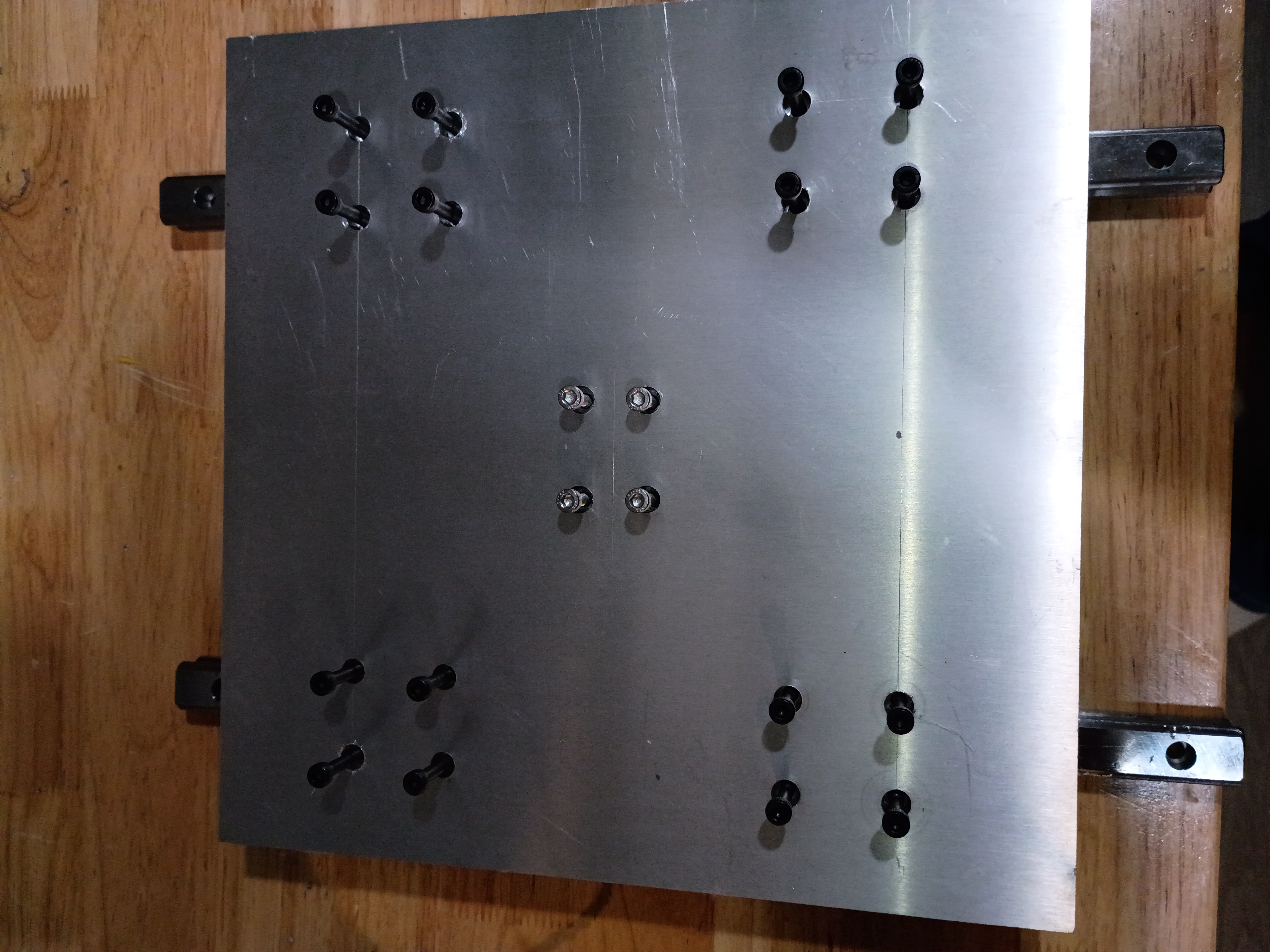
Compiled the full project code from the minimum viable test cases, but I am unable to test it easily until USPS delivers the 7-segment breakout PCBs, which were supposed to be delivered yesterday.
Threw a quick GPS data display together using a Pi Zero (overkill, used only for the USB GPS dongle). It shows lat/long/alt/speed and the fix status and number of satellites observed. 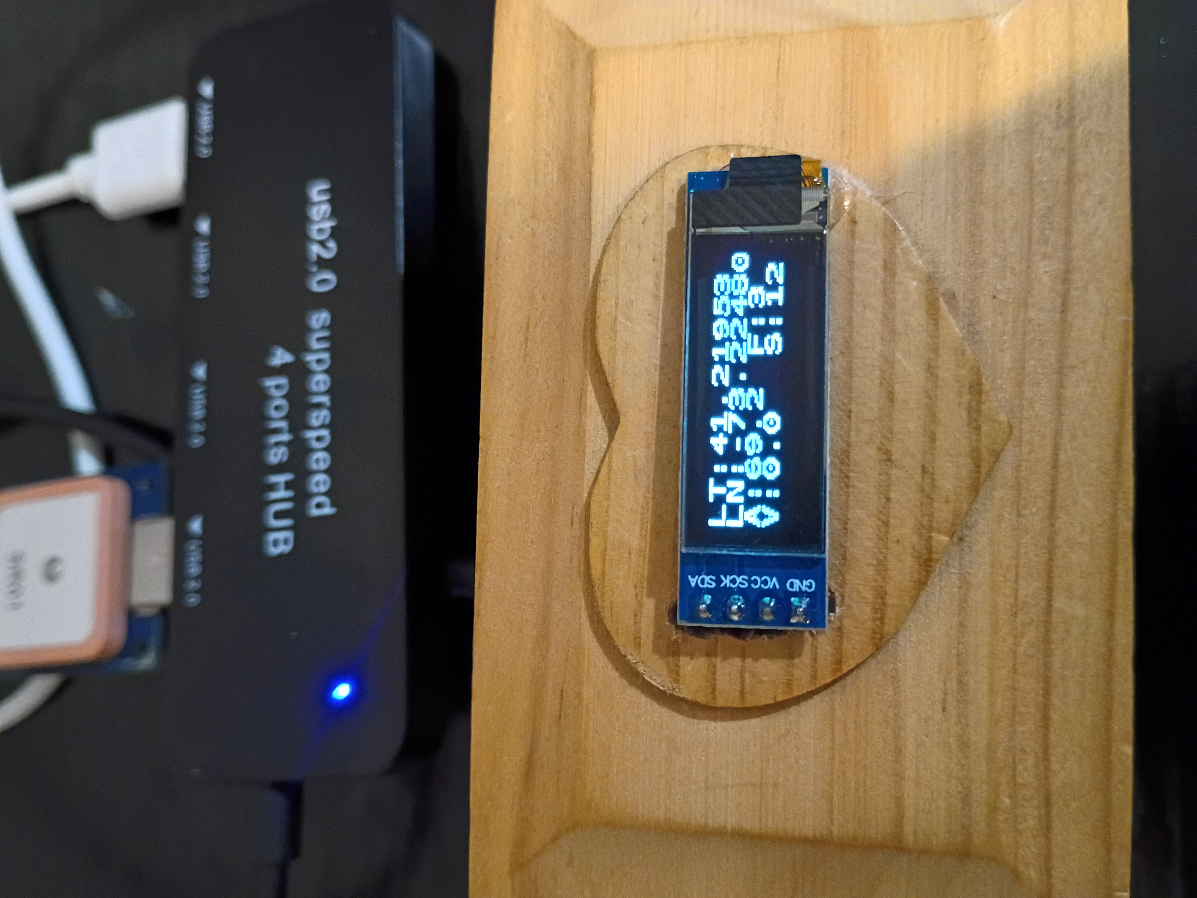
Here is an isometric view of 03009 MM1 Minute Hand with a 'cutoff' from the front panel.
I updated the web journal-generating script to add some additional info and formatting.
Began to drill and counterbore mounting holes for the X-Y gantry plate. These slotting counterbore bits are really nice but get gummed up quickly and stall the motor of my weak drill press. Also have to use a cordless drill to reach the central holes. Would be nice to make a nice drill press. 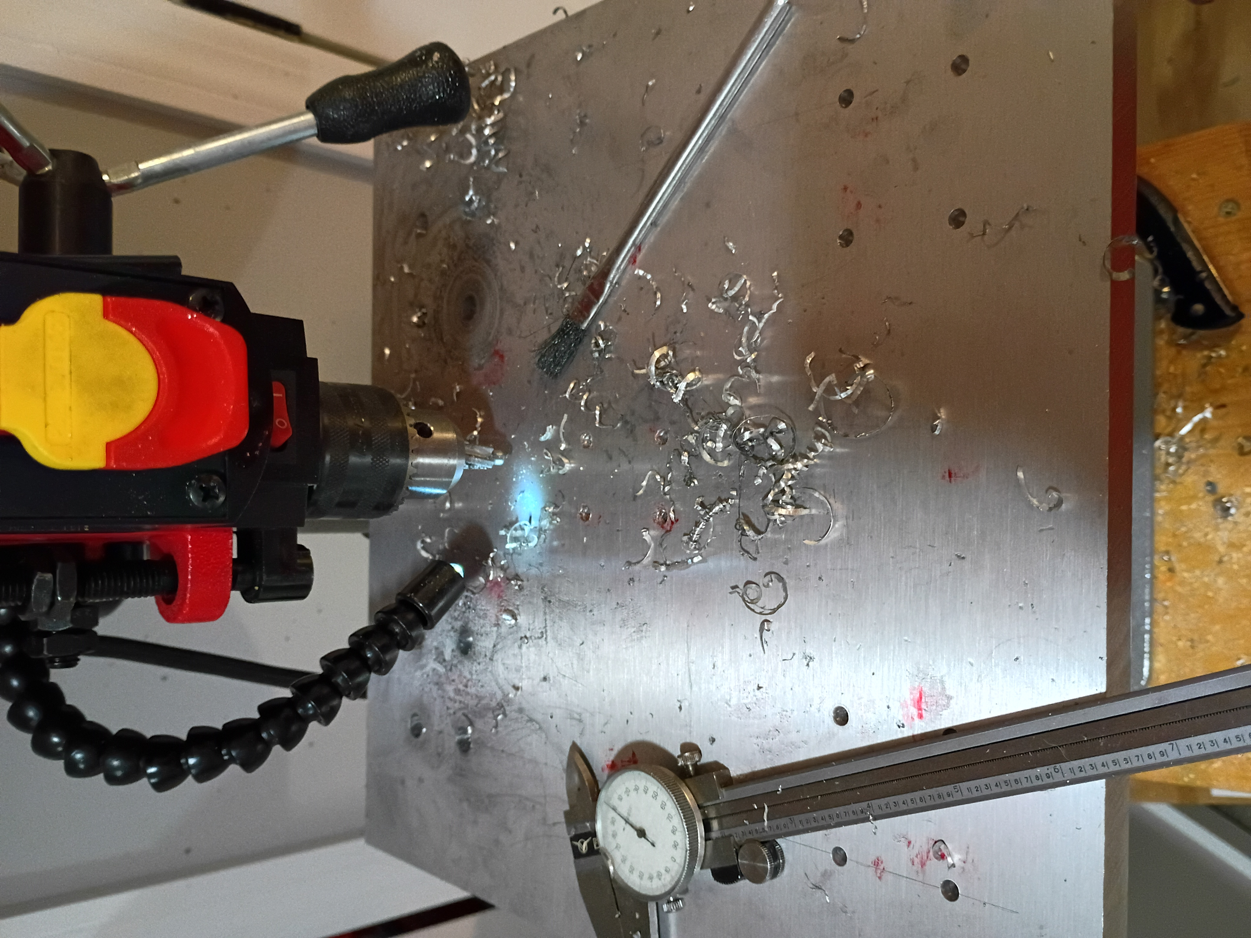
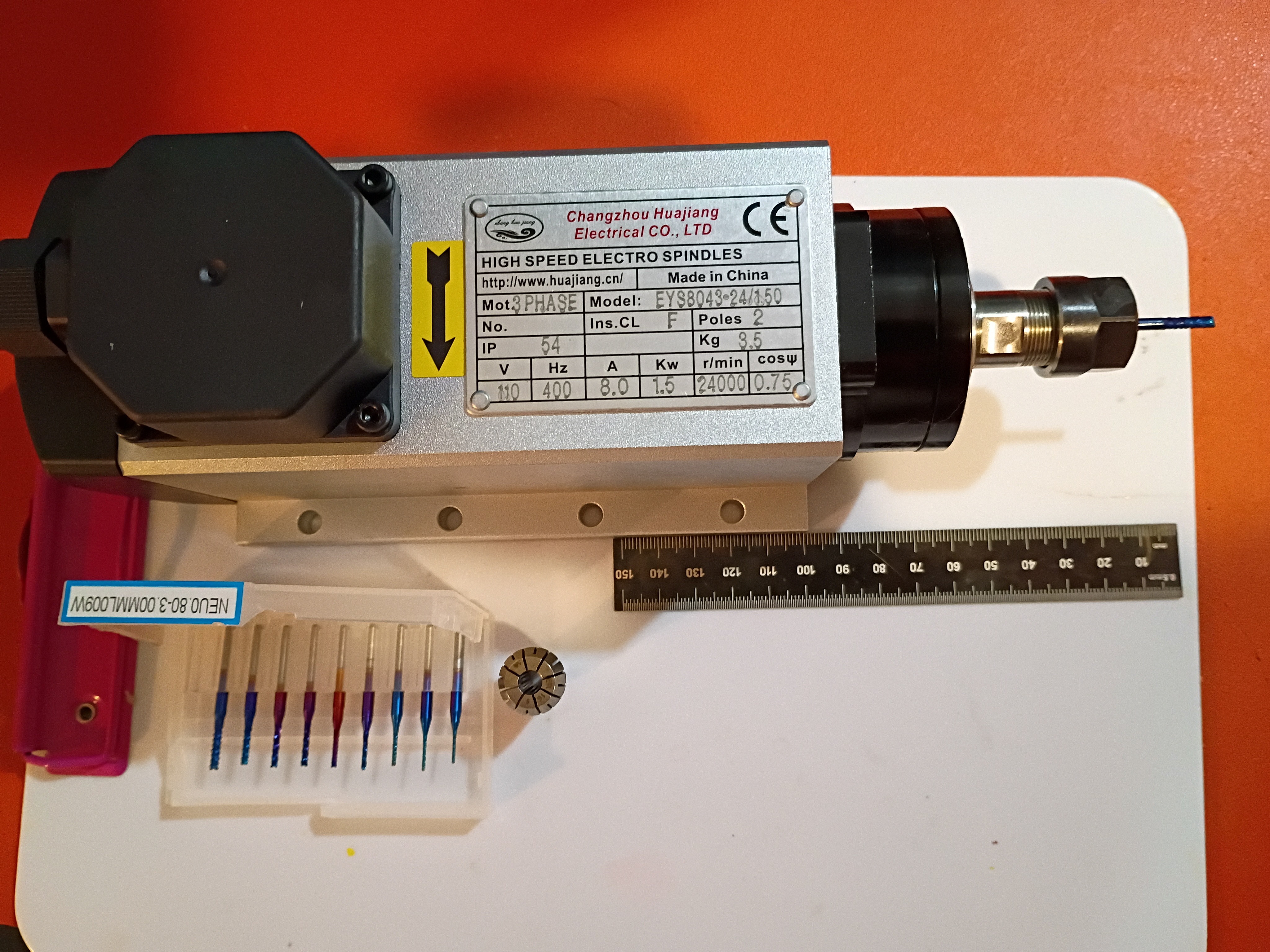
Took inventory of CNC mill project after long hiatus. Updated CAD model to reflect length of installed collet and bit and migrated to organization repository. Marked out the drill and tap locations for the X-Y gantry plate. 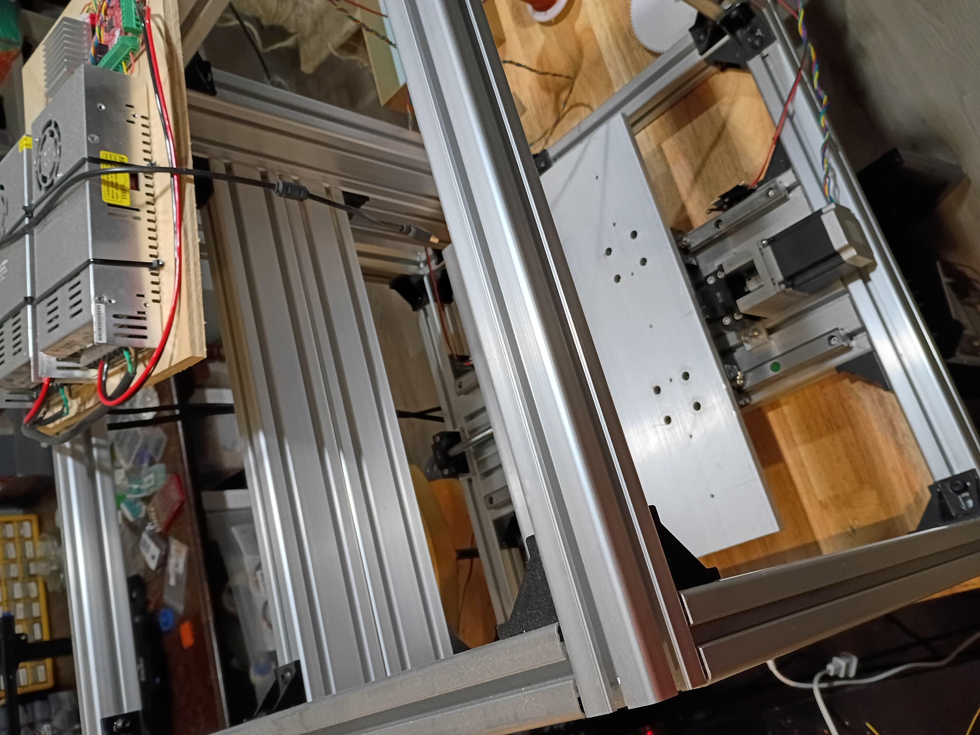
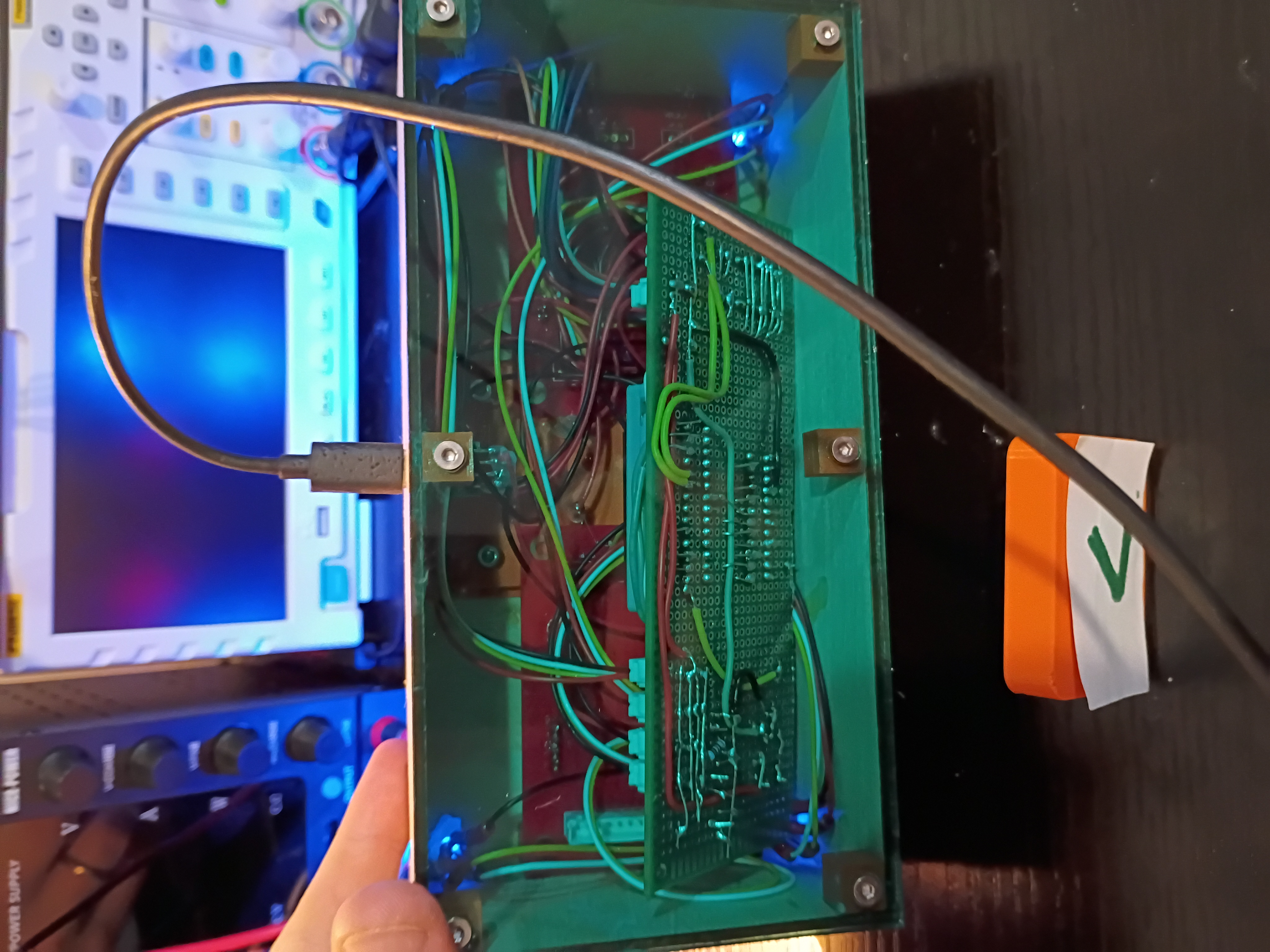
Snipped down main circuitboard to fit snuggly inside the box. Debugged minor soldering issue with one of the RGB LEDs. Wrote this code to control the lights in unison with the buzzer depending on the reed switch status. See video example. 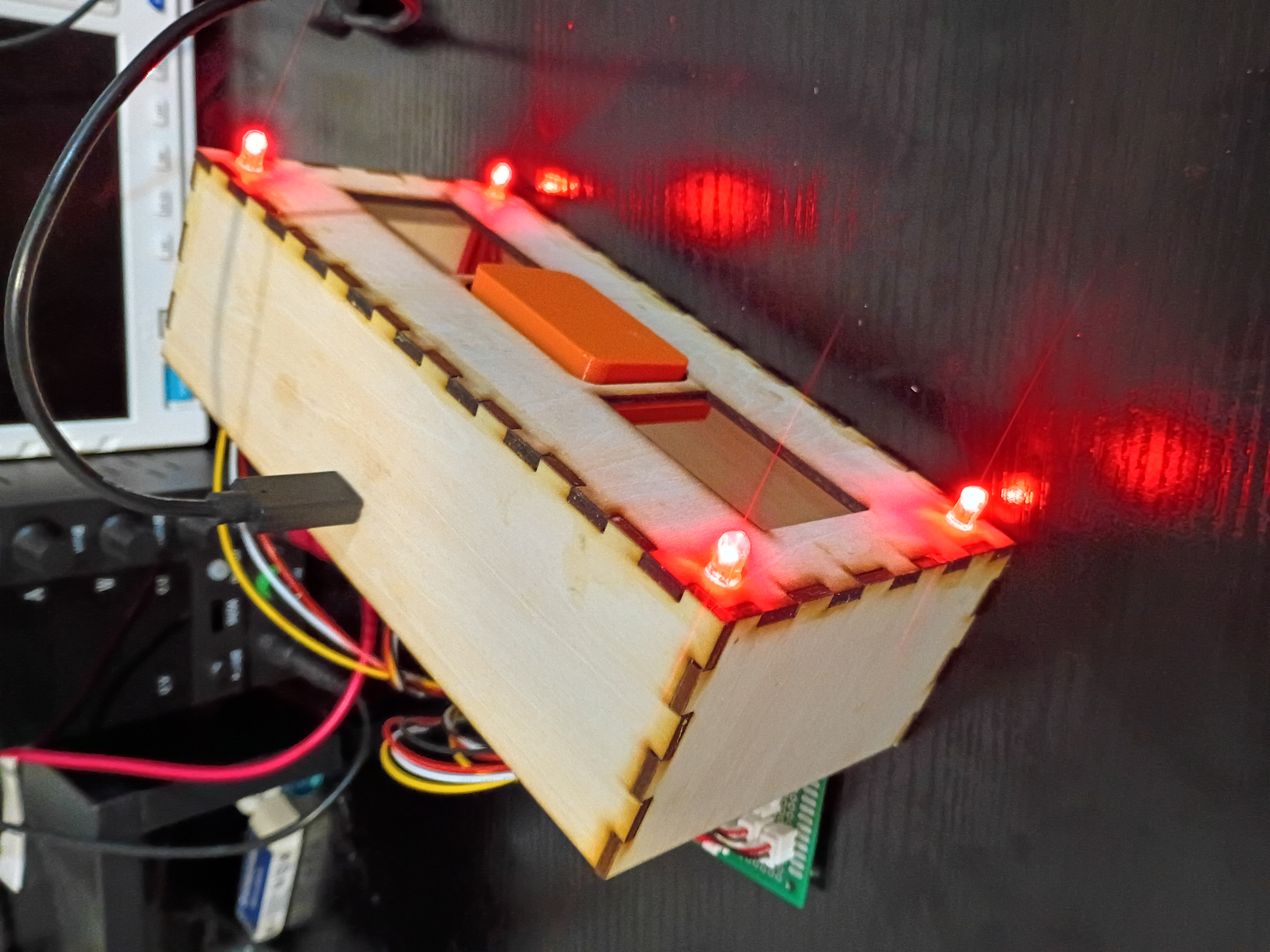