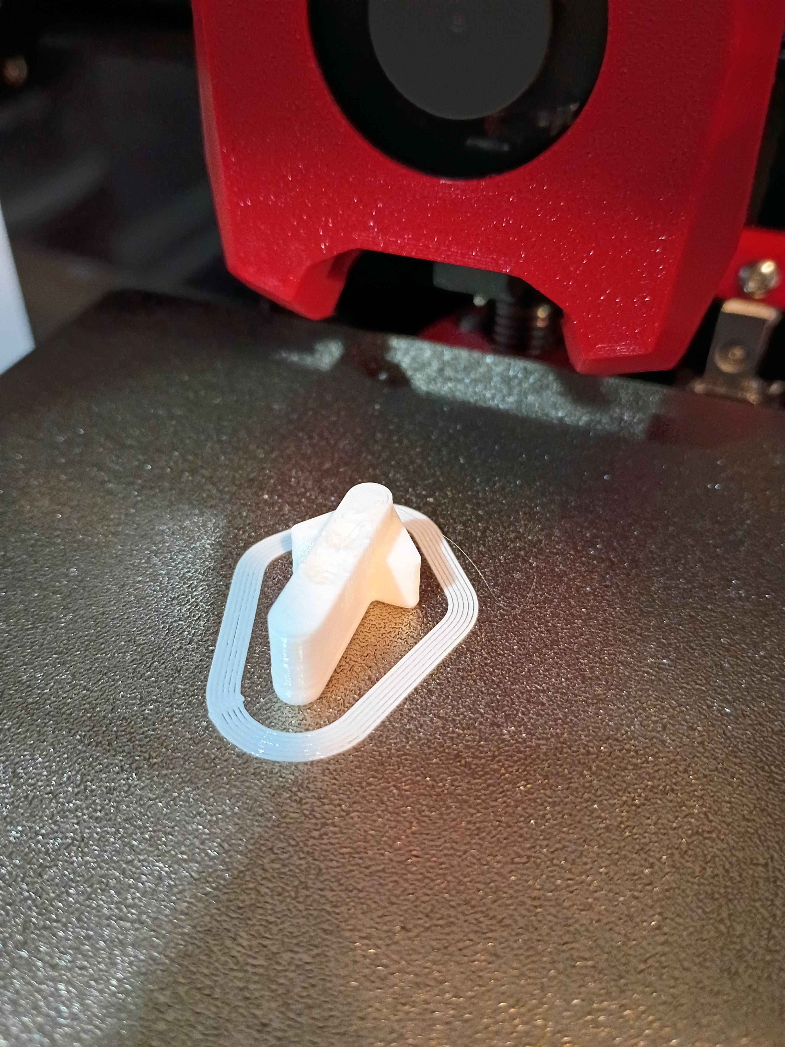
Designed and printed a (very small) magnetic input device. After some preliminary test fits, I decided that the slots in the slotted reed switch assembly needed to be slightly wider, so the entire assembly was redesigned and will be printed at work this week.
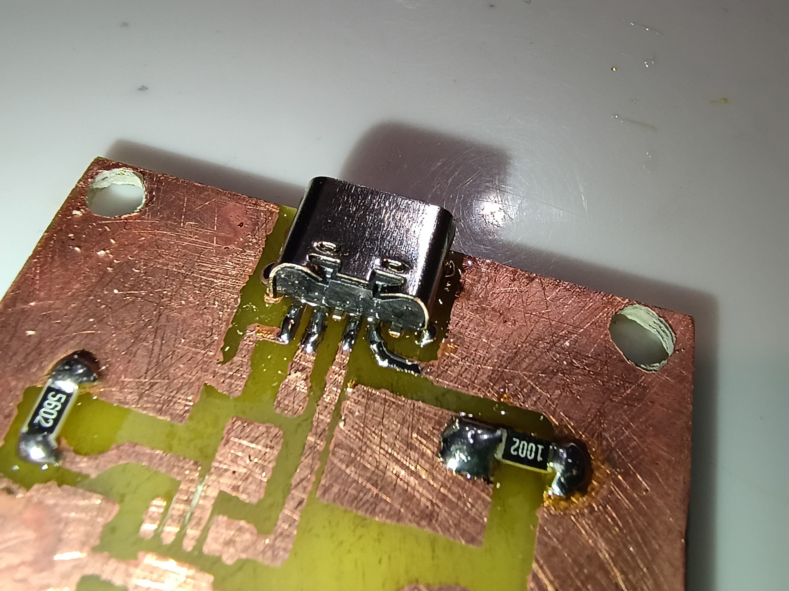
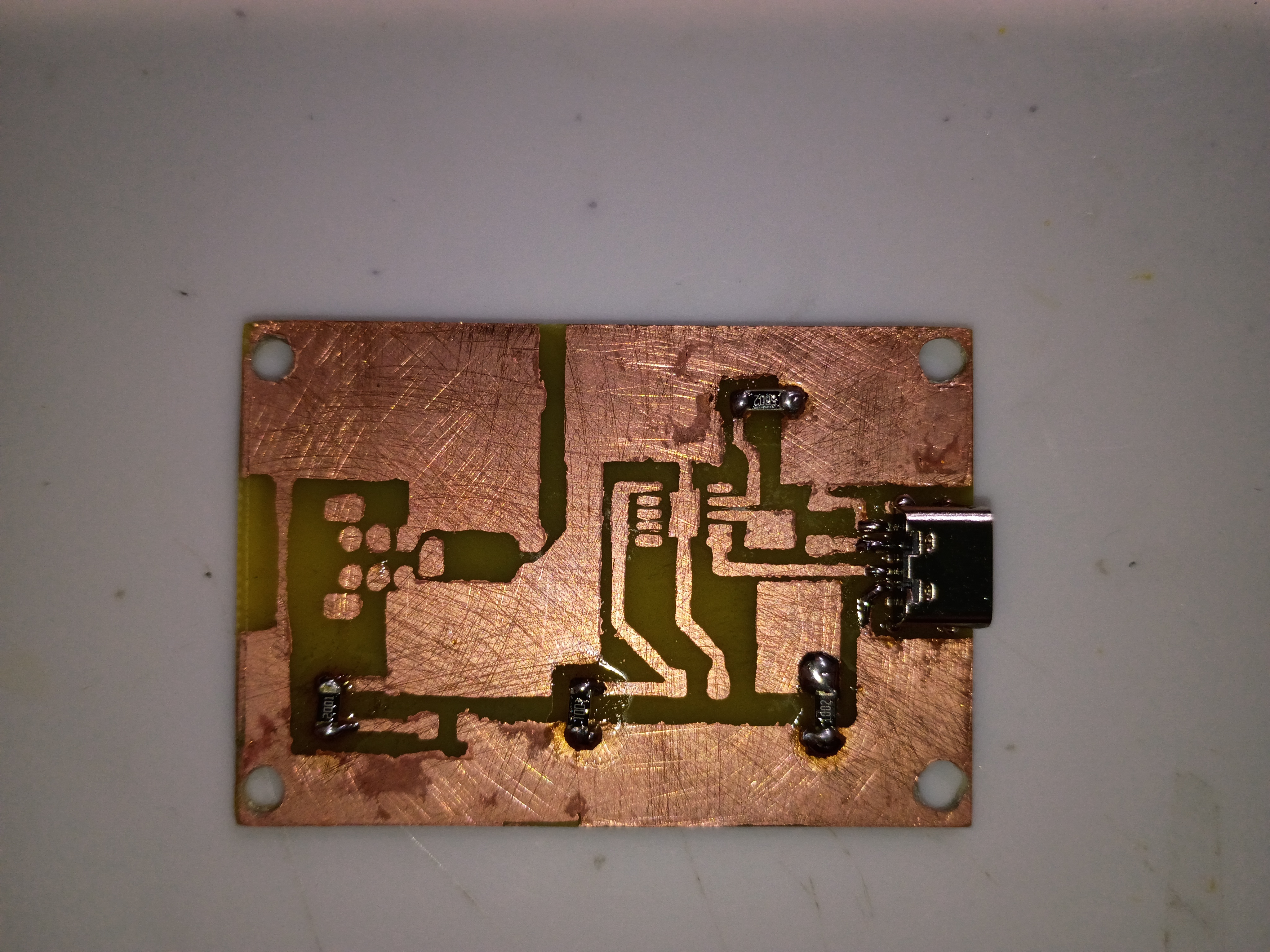
Reviewed the box assembly and PCB designs for manufacturing considerations and provided feedback to the designers. Incorporated the manufacturing feedback into the box assembly. Soldered SMD resistors and USB-C connector (required 1.0 mm holes drilled) to the test board. Purchased ASA filament for the eventual final box print and the necessary capacitors for the circuit. 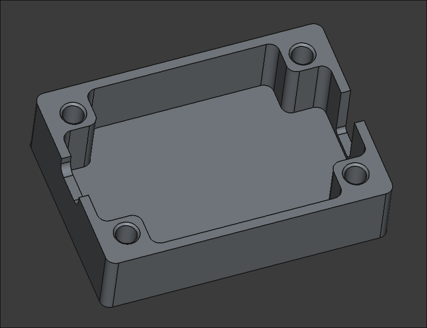
Yesterday, a PCB of the Firewire PD was designed. This design is designated for prototyping and isn't considered final. Surface mount components will be used for this project and thus the copper for this will be on the top (front) as opposed to earlier designs where the back was reserved for the copper. There is one rear copper connecter that will be implemented via a jumper.
Fabricated the preliminary base PCB, while demonstrating to Anthony. Holes were drilled for assembly. On the next iteration, the copper pours on the mask should be exactly sized to the edge cuts, the hole patterns should be brought onwards roughly 1mm in every direction, if possible, and the box assembly should allow for an extra 0.5mm of tolerance around the board edge. That being said, this assembly will serve as a testbed for the circuit when all components arrive. 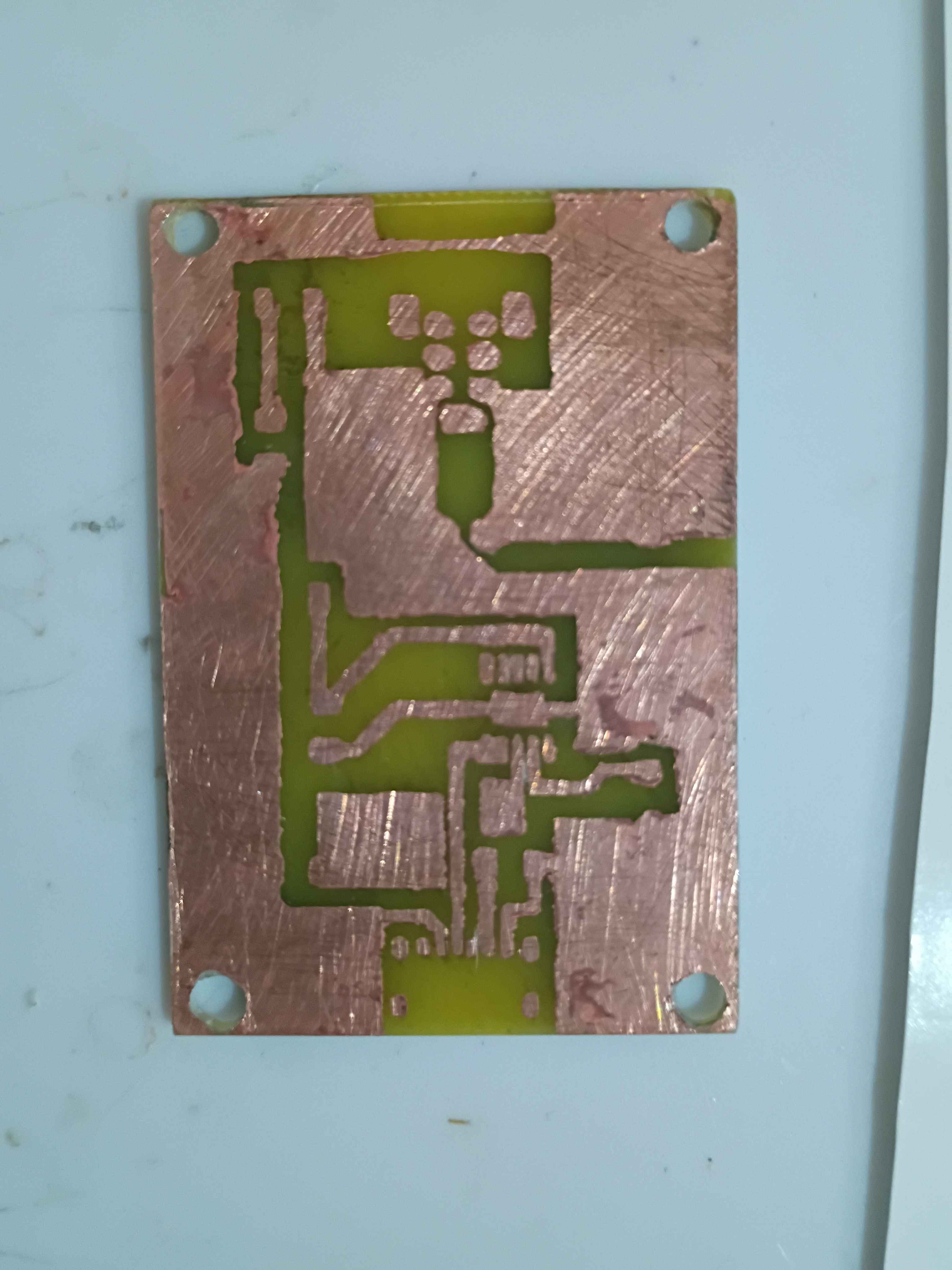
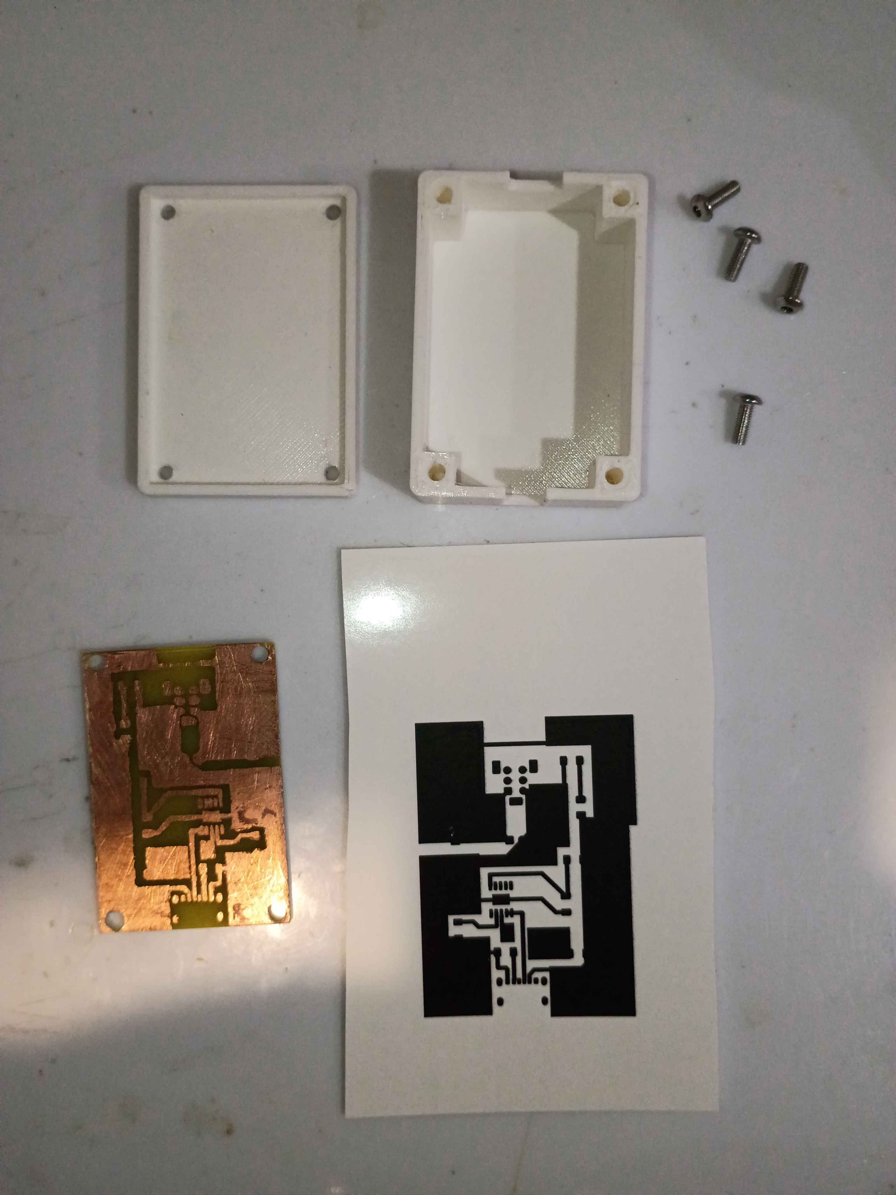
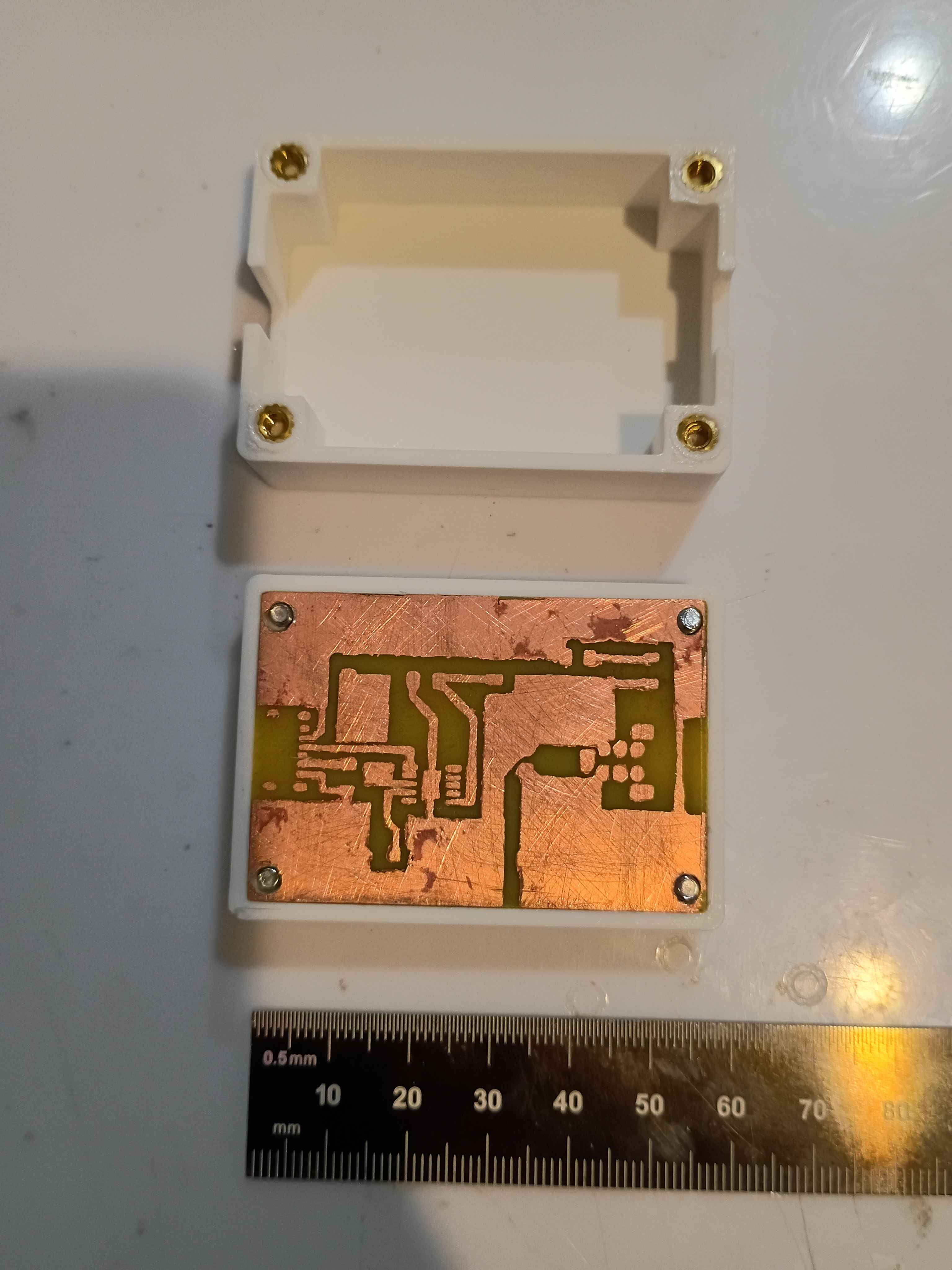
Consulted on the PCB layout and mocked up a draft two-piece box assembly with notional slots for the connectors. Sliced and launched a test print on the new facility Voron 0.2r1 printer using PLA. Assembly will take 4x 3x4x5 M3 heat-set inserts for M3 socket head screws that clamp everything together at once. 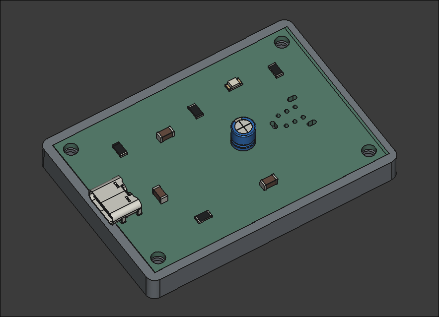
The DIP Firewire (Keystone makes a version called 930) was ordered and the 4 pin Firewire was ordered. The DIP Firewire ordered from here and the footprint was modeled from here (the 930 from Keystone Electronics). There wasn't a footprint model provided from the retailer, so one was taken elsewhere. The 4 pin Firewire ordered from here had a footprint provided and my custom footprint was modeled from that.
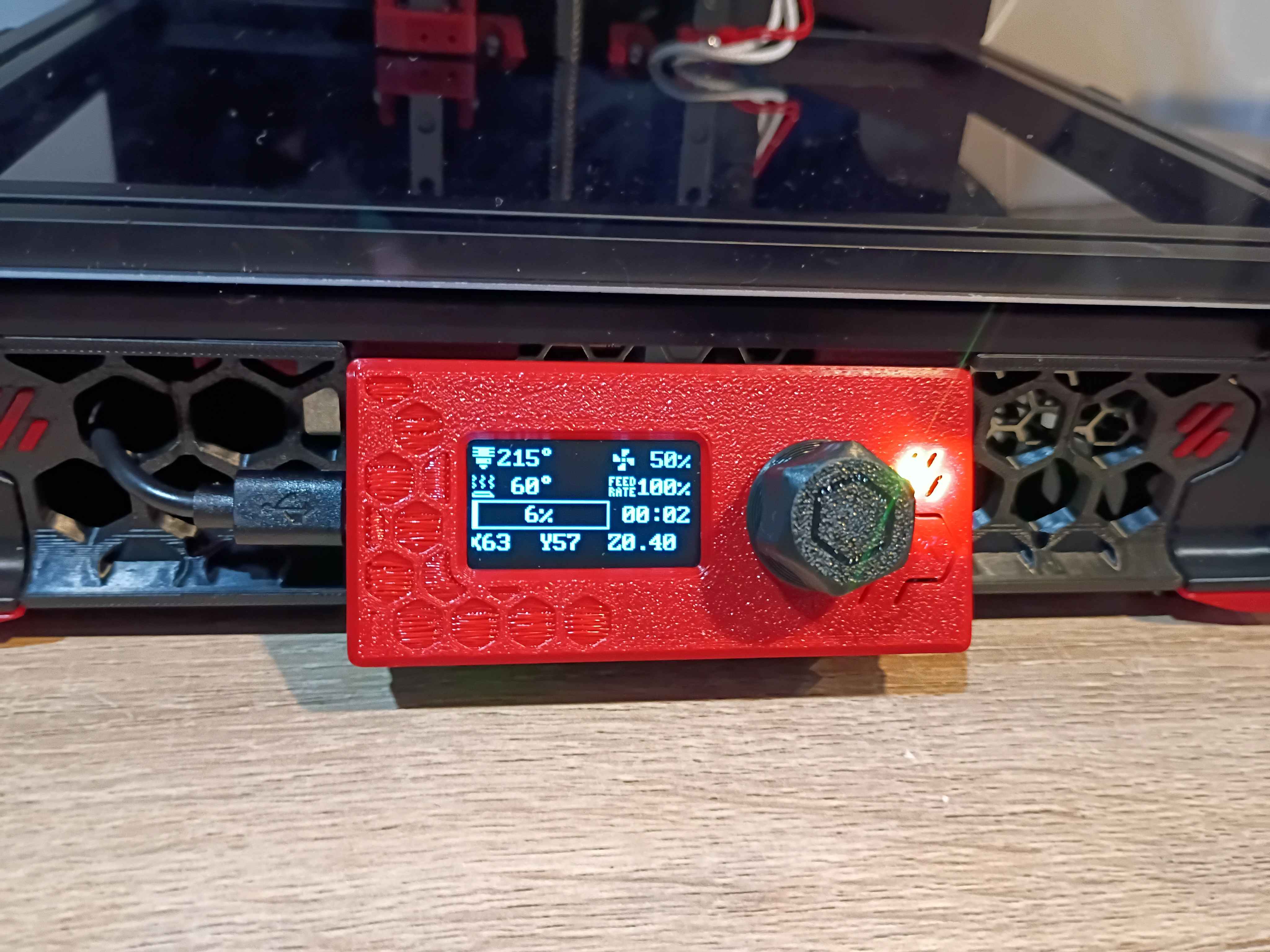
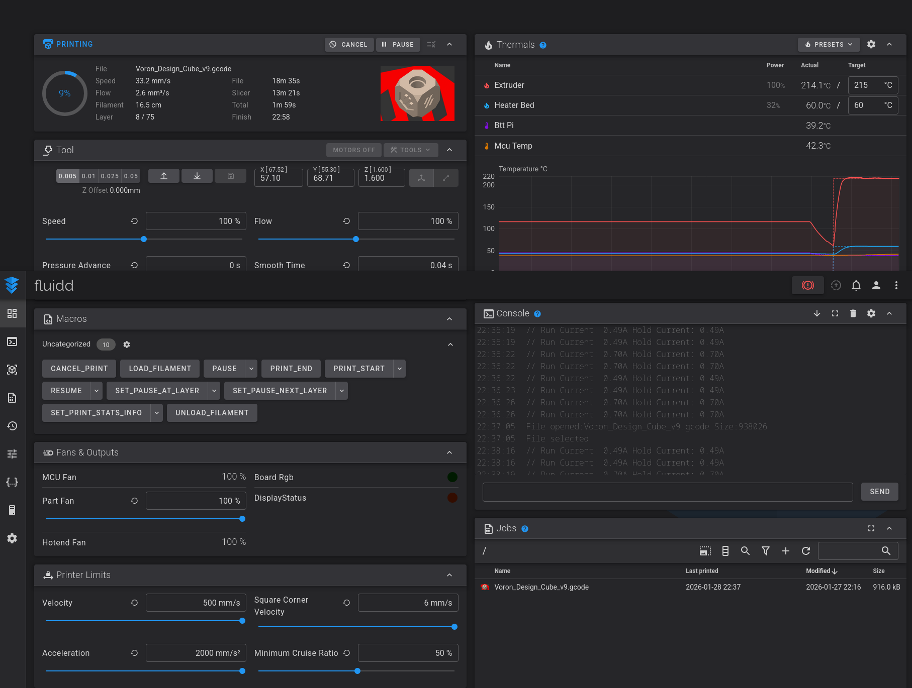
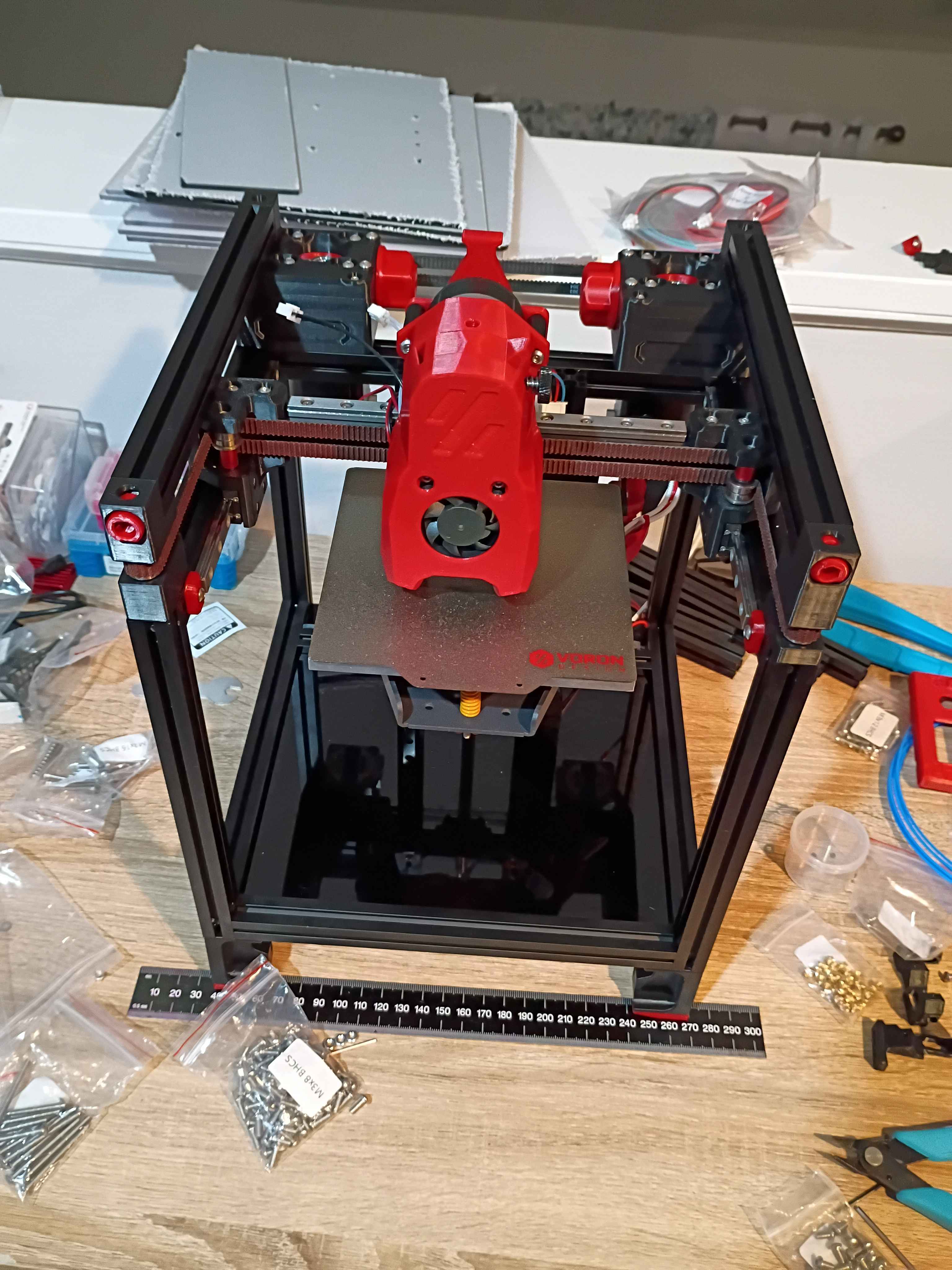
Essentially completed the Voron v0.2 build. OLED display works, wire management reasonable, back panel and top hat installed, spare parts stored away, workspace cleaned, configuration mostly set up. Several test prints completed successfully. More fine tuning will come in time, but this seems way more reliable for my purposes than my old Ender 3 V2. Props goes out to the Voron developers for this. Inspires me to make a more barebones version with a much shallower Z-depth and fewer components in general. See video of it in action. 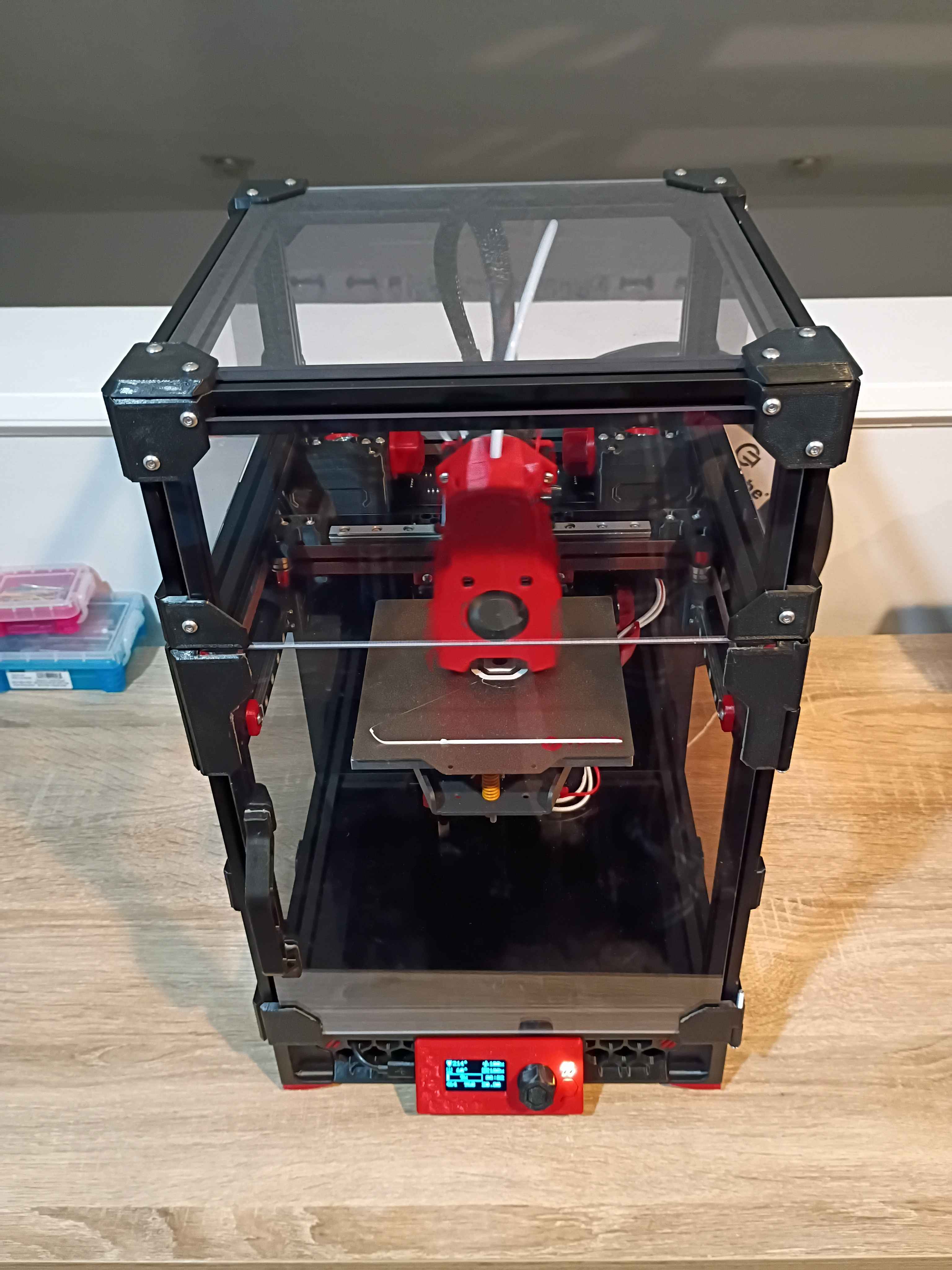
A couple of days ago, I was tasked to create a PCB that essentially converts power from a USB-C to a firewire socket. A rough schematic was made and a custom footprint was created for the anticipated firewire female port. Yesterday, the Schematic was updated from a reference workflow doesn't have a footprint for the IEEE1394 (firewire) female port. So a suitable part was researched for this project and one was found on mouser here and Digikey as well, here . This is the 929 by Keystone Electronics. This datasheet schematic was used to make a custom footprint for the 929. Here's the custom footprint.
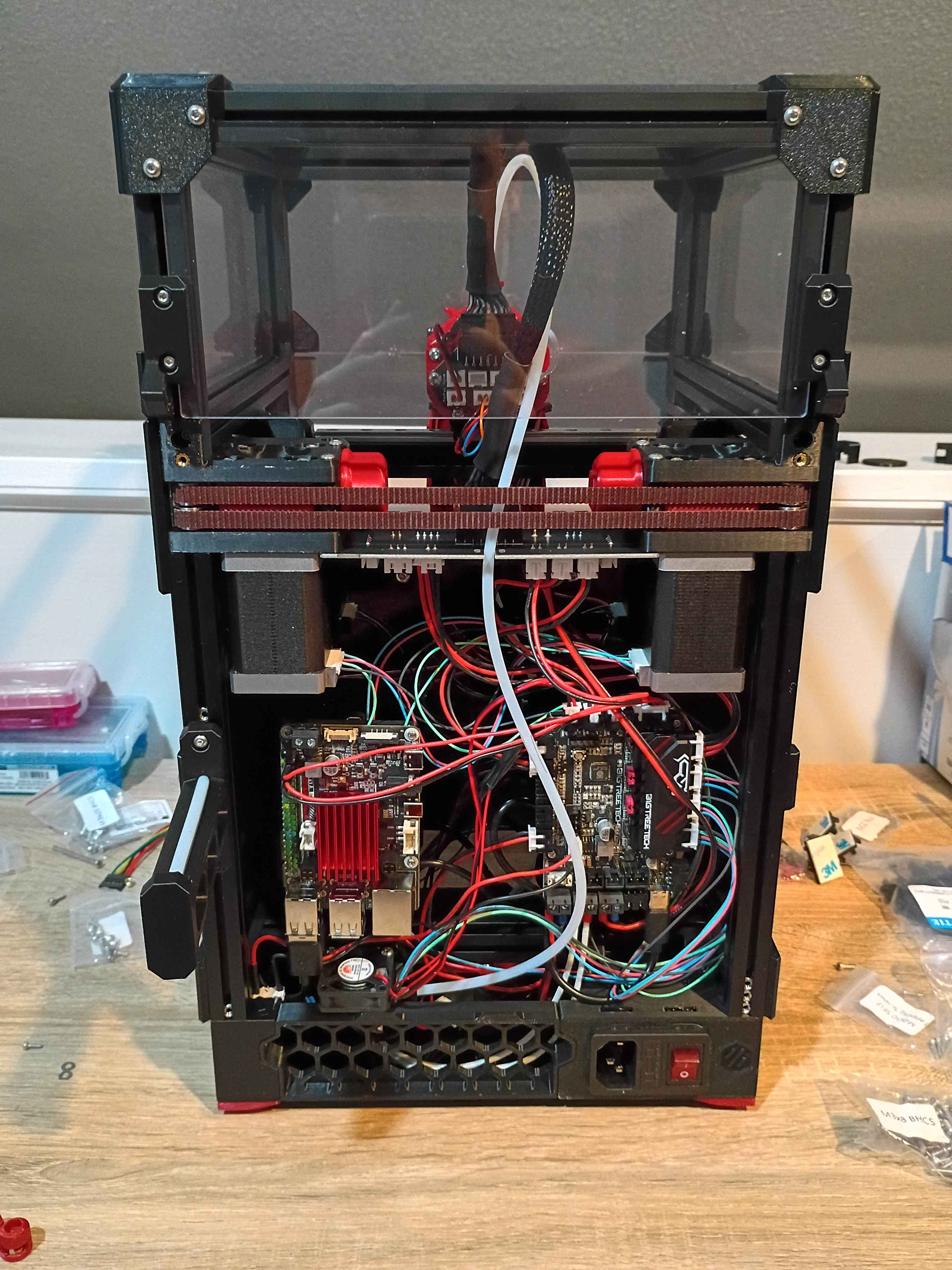
Fixed some minor electrical and software issues on the Voron v0.2 and got it printing successfully! The main issue with the electronics was that 2 sets of 2 wires were mislabeled, so I was sending negative 24V to the part cooling fans and negative 24V to the extruder fan. Found the issue, swapped them around, and it was fixed. Spent some time tuning config parameters and leveling the bed. Now that it works, tomorrow I can enclose the electronics and wrap up the build. Also the OLED display needs to be properly connected and configured - right now it only shows some default sample text. I think I'll also clean up the wiring slightly and eventually get some kind of air filter system to print ABS, though that can wait. 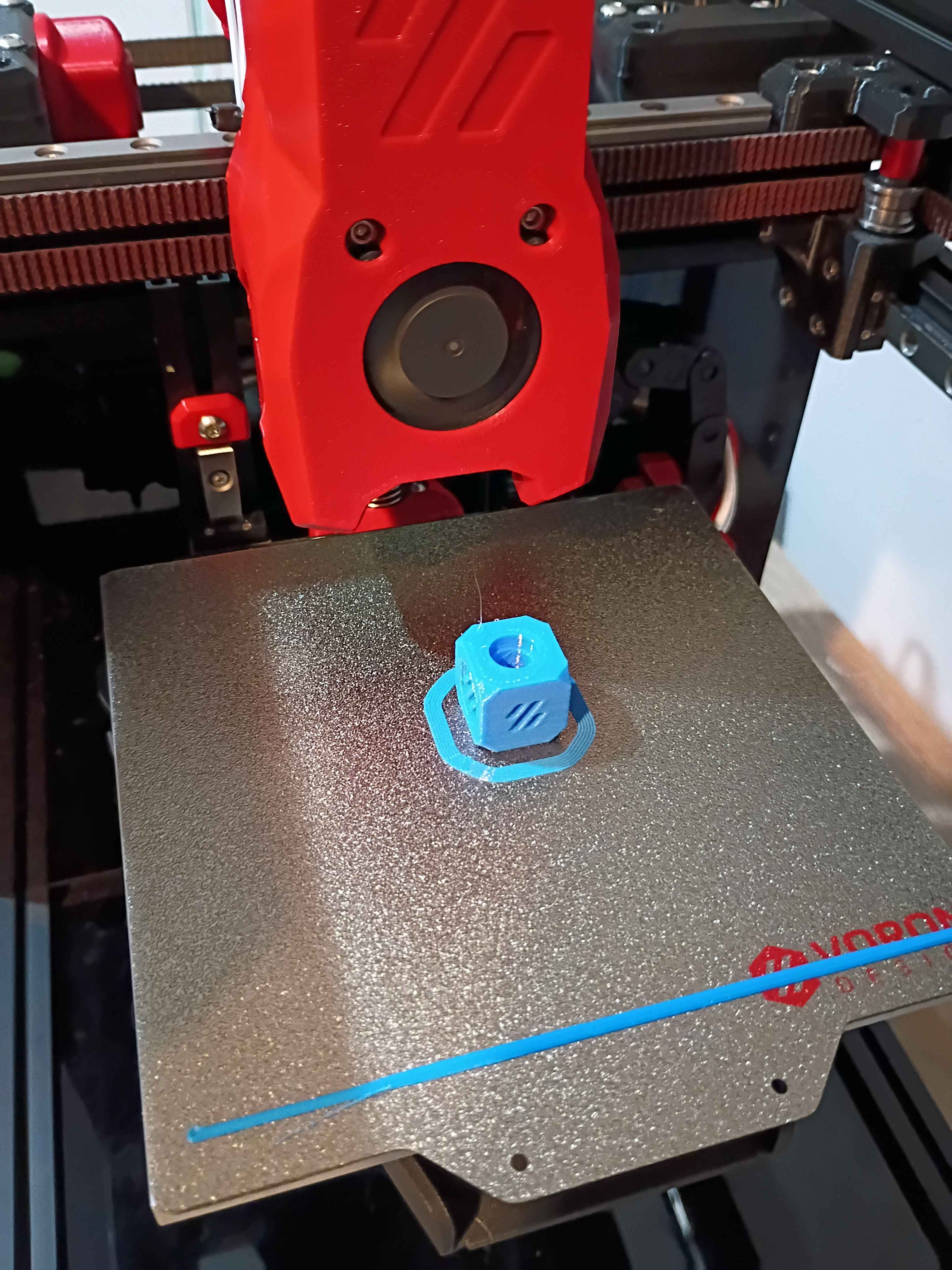
Helped launch project by brainstorming solutions to client request, conducting research, purchasing necessary components, and assisting with preliminary draft circuit schematic and PCB layout. 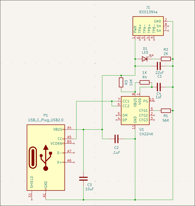
Continued to set up firmware for the Voron v0.2. Have the OS set up, and I'm just working to get the SKR Pico and OLED screen connected successfully.
Wrapped up most of the Voron 0.2 r1 build. The only thing remaining is the back panel cover (and hinge for the top hat) because I am hesitant to believe I wired (guessed) all the electronics correctly, and you can only access them from the back. Once I have the software set up and can validate that the electronics works, I will wrap up the final few operations. Also, although it's not necessary, I'd like to add more screws to the z-axis linear rails and upgrade the part cooling fans if not the entire hot-end system, but those can wait until after the printer is working and mostly tuned in, likely later this week. 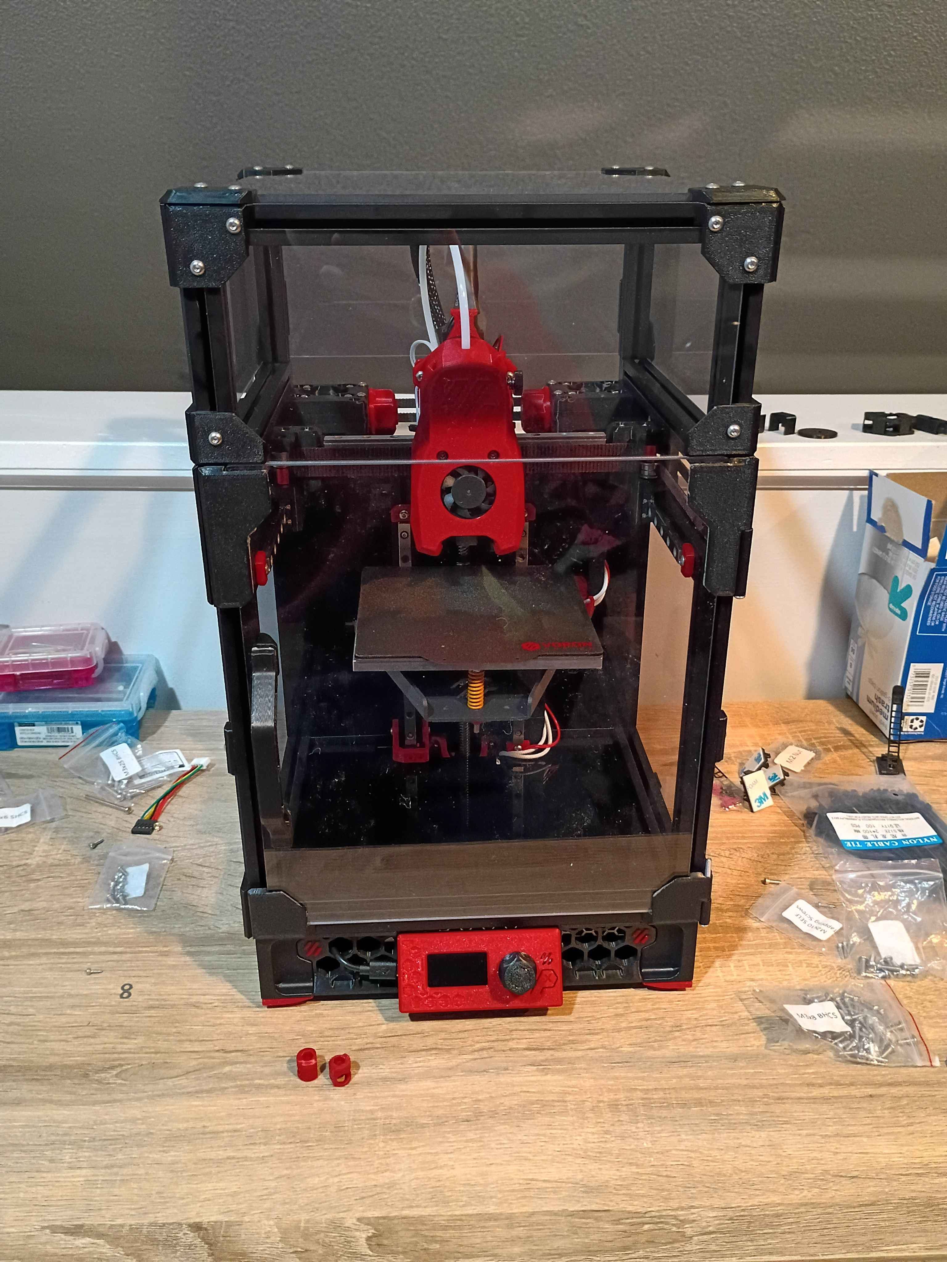
Continued to work on the Voron 0.2r1 kit. Completed most of the frame, motion system, and toolhead. Probably only 1 more day. 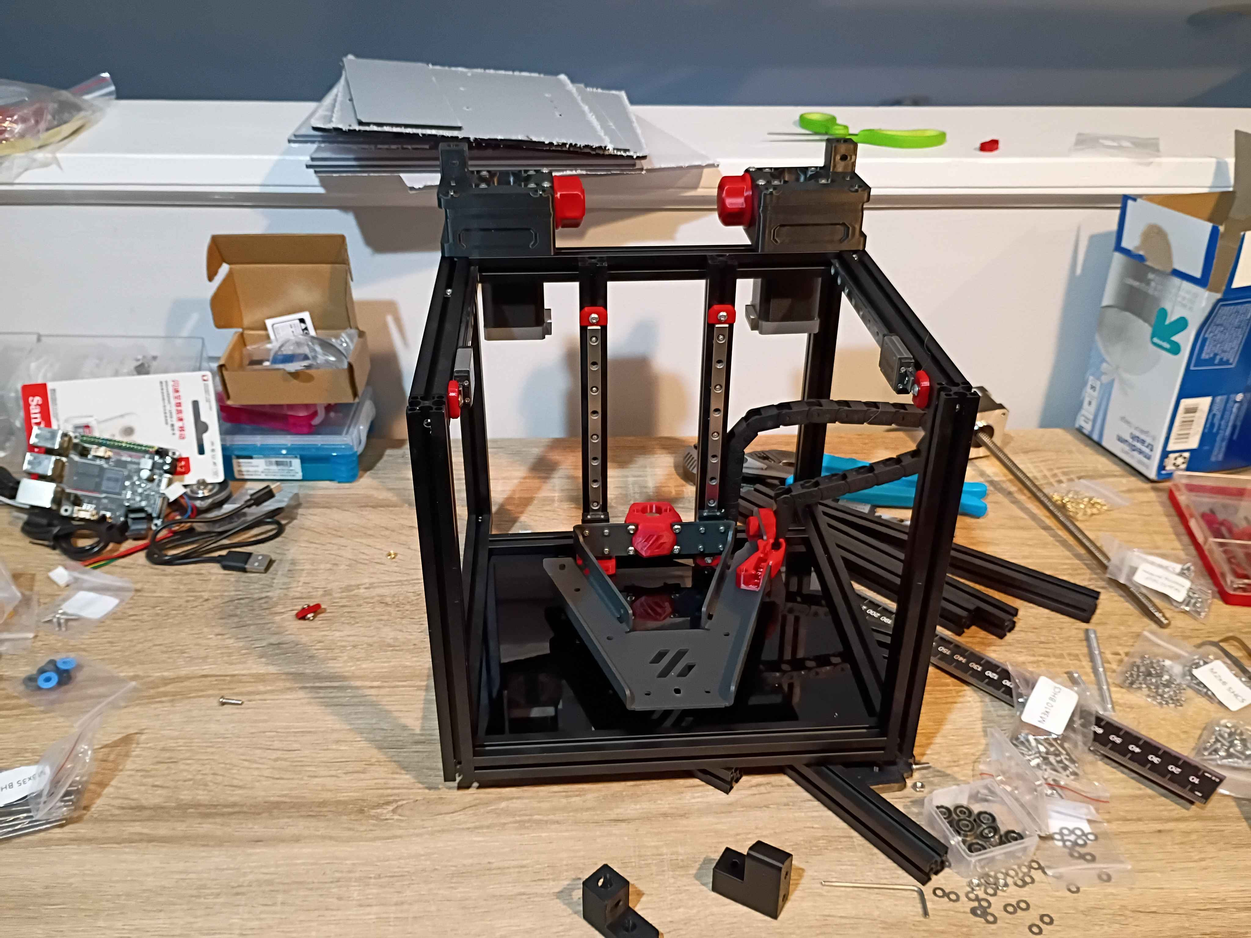
Started kit build of Voron 0.2r1. 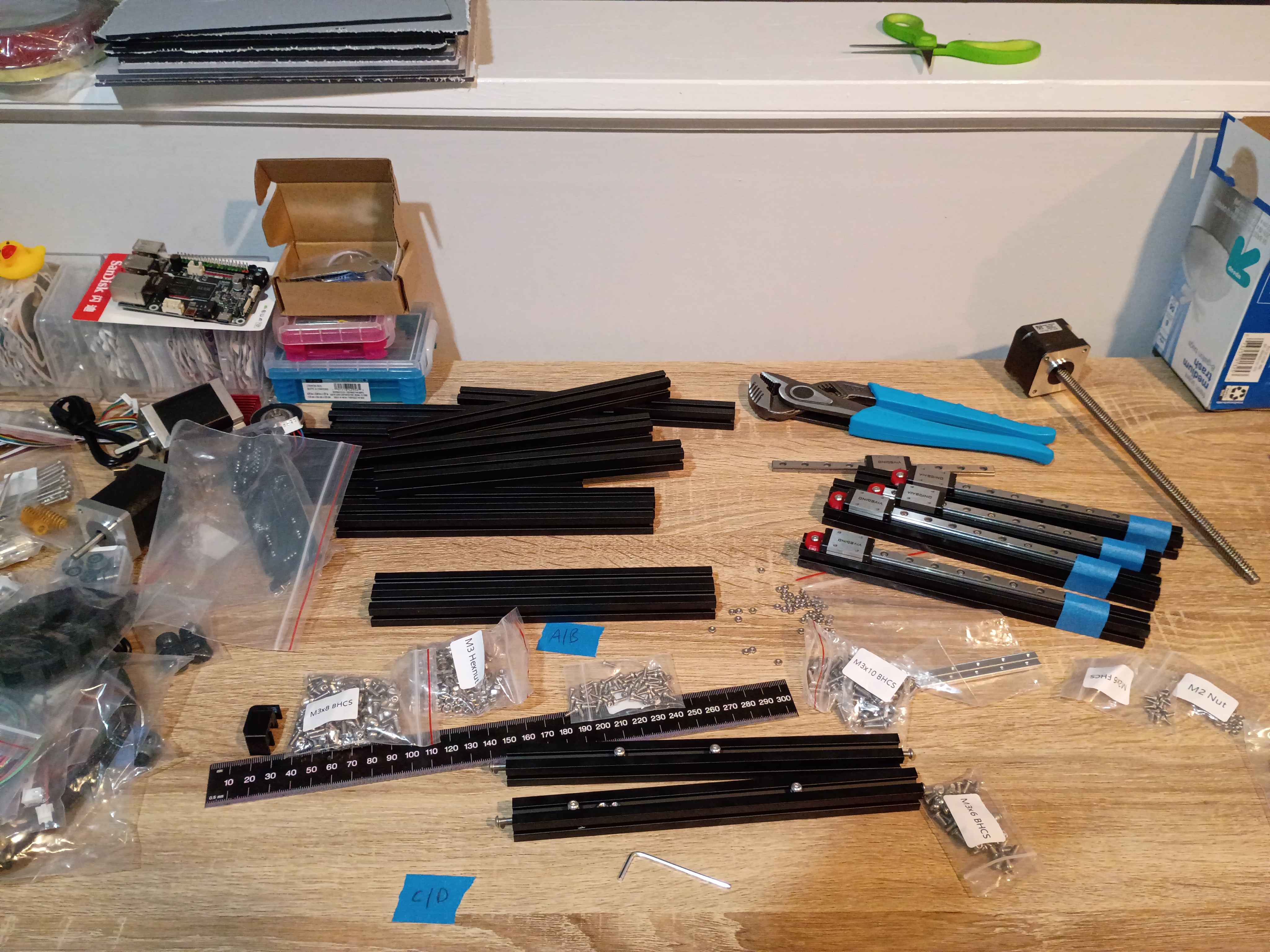
Laser cut some 03010-001 rulers. 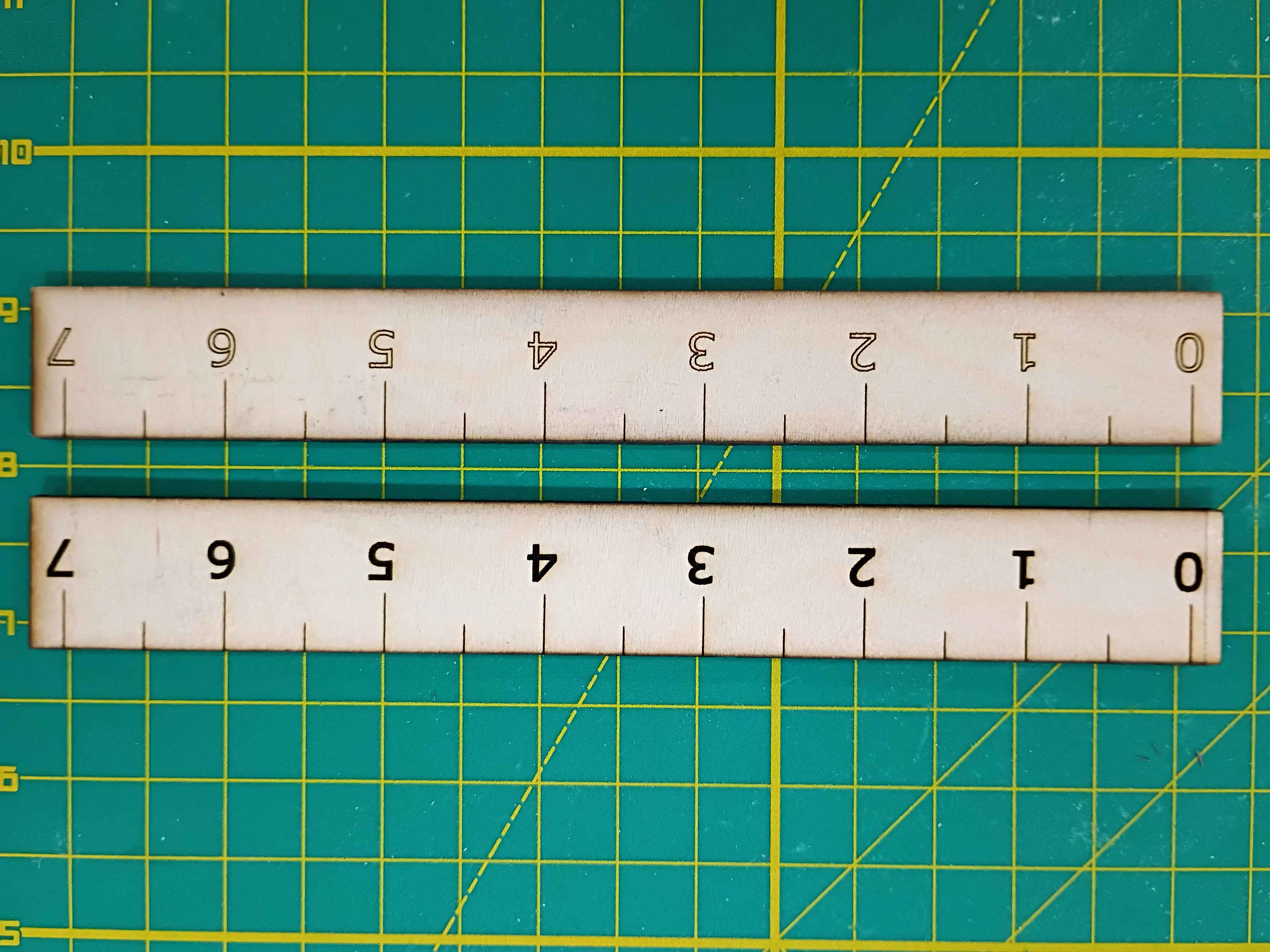
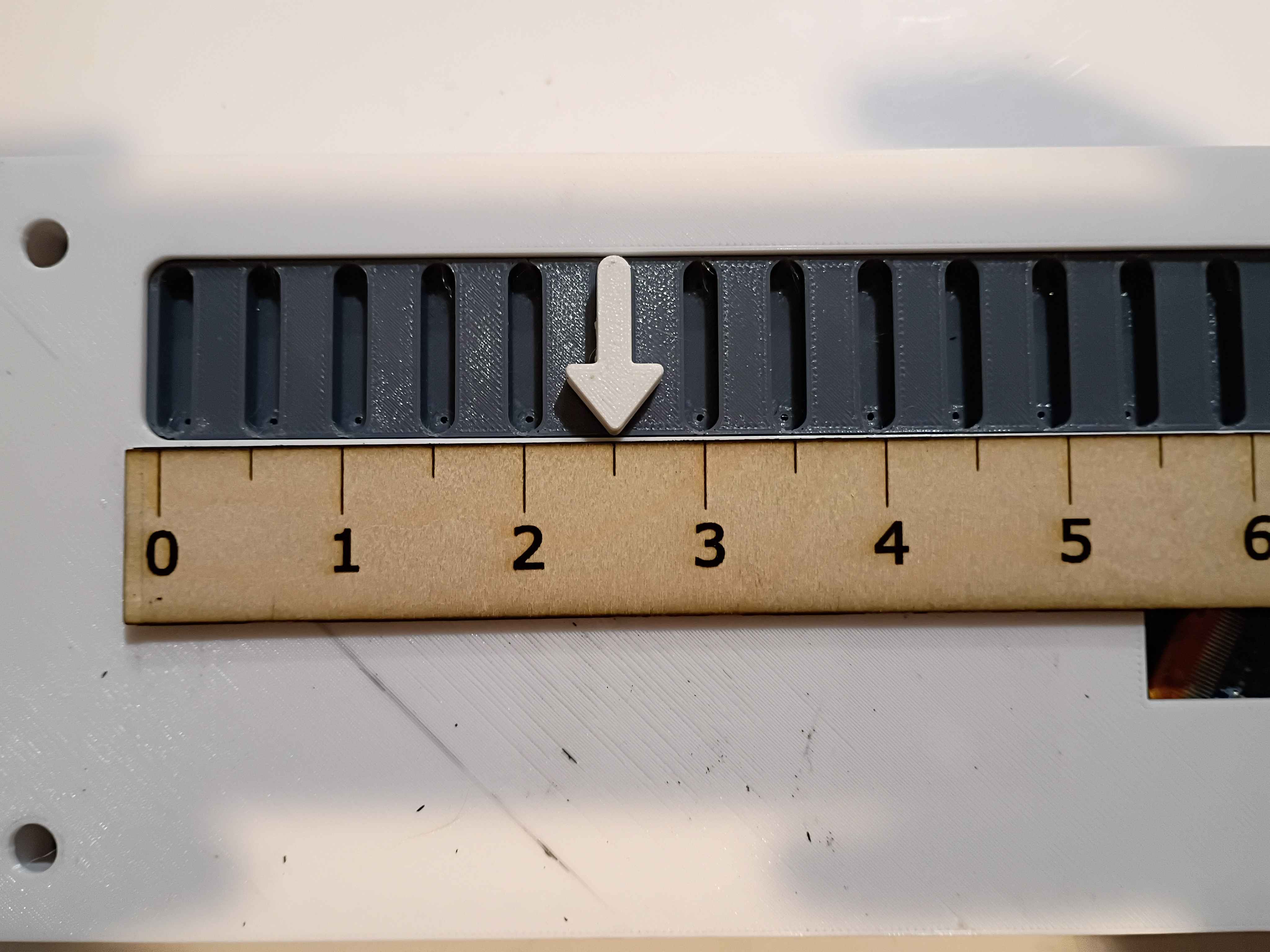
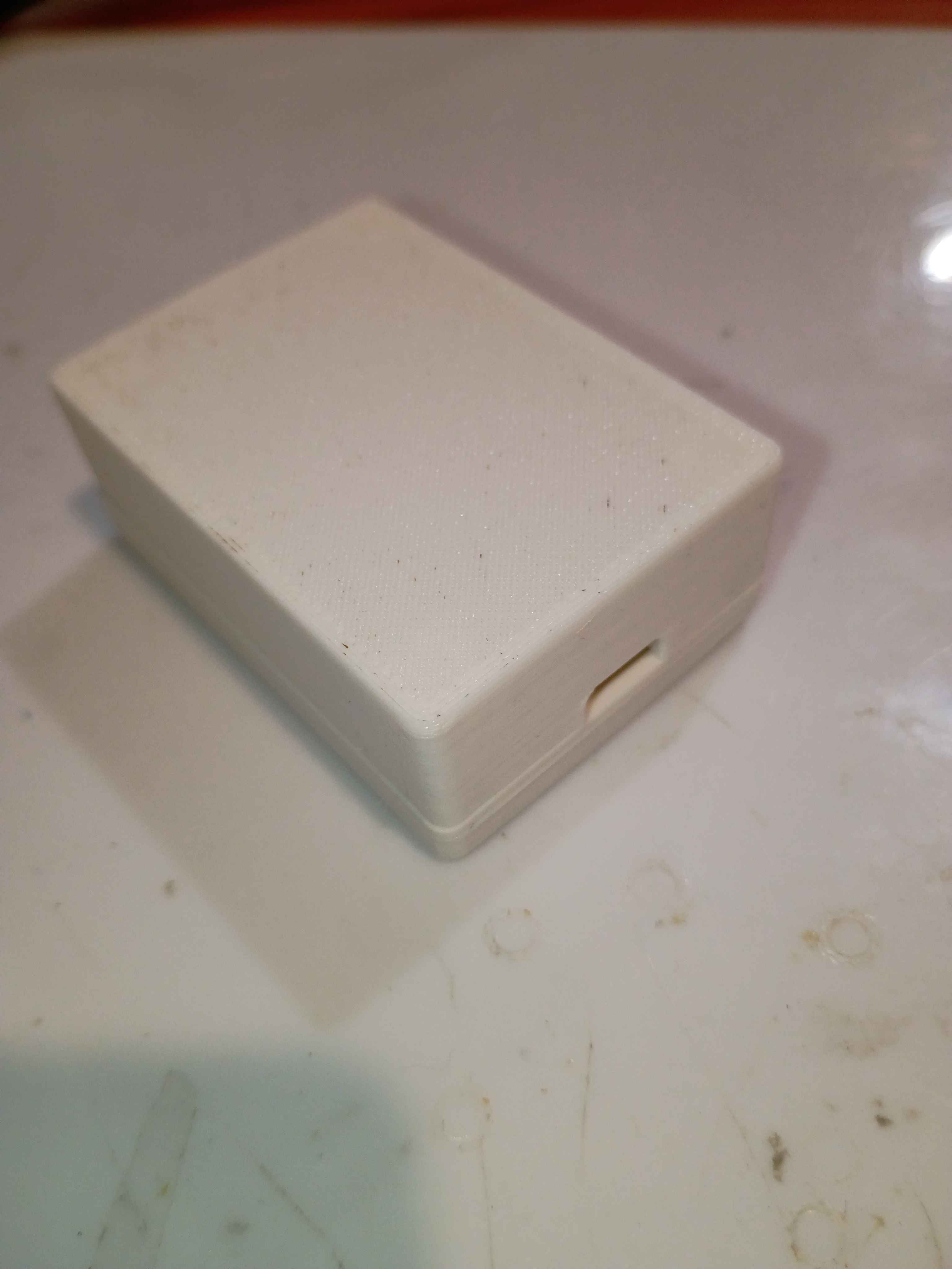
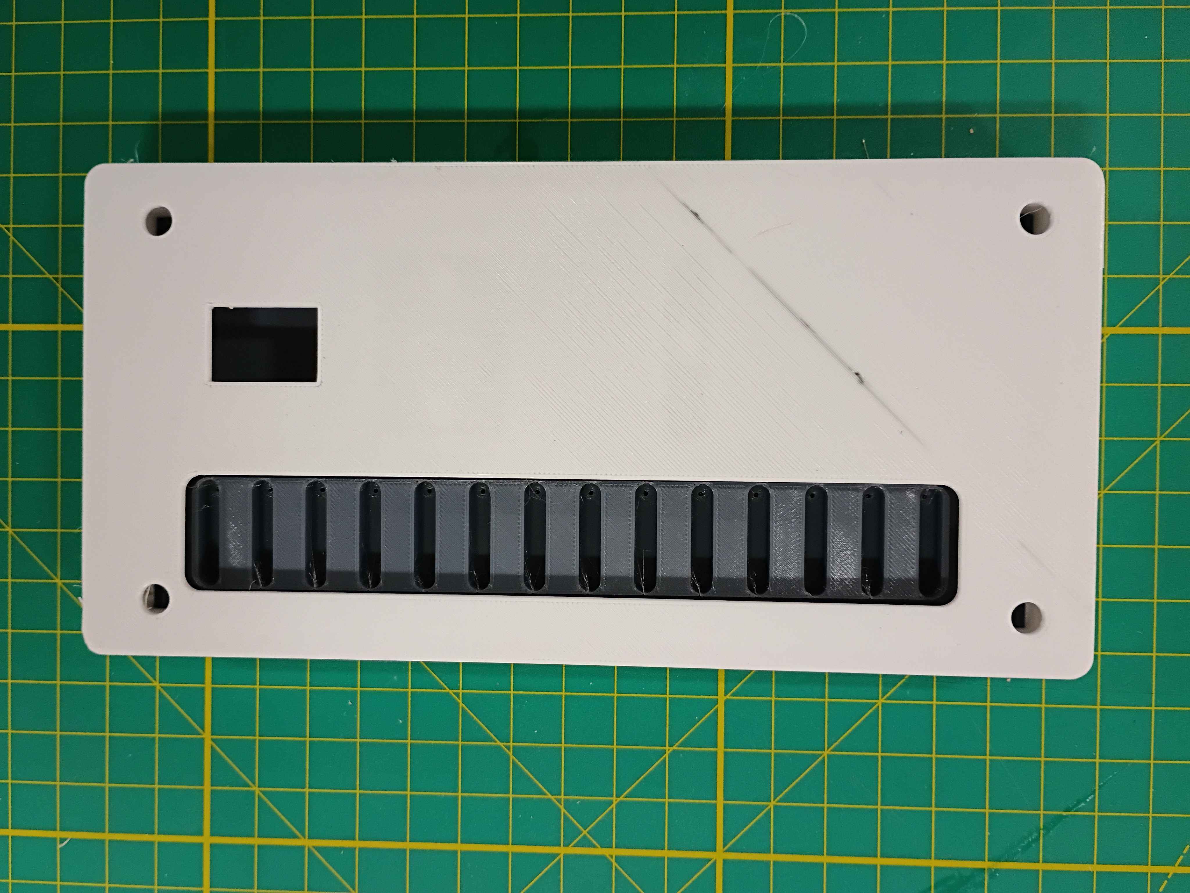
Tested box layout. May need to reprint the white body piece with the OLED cutout slightly lower. 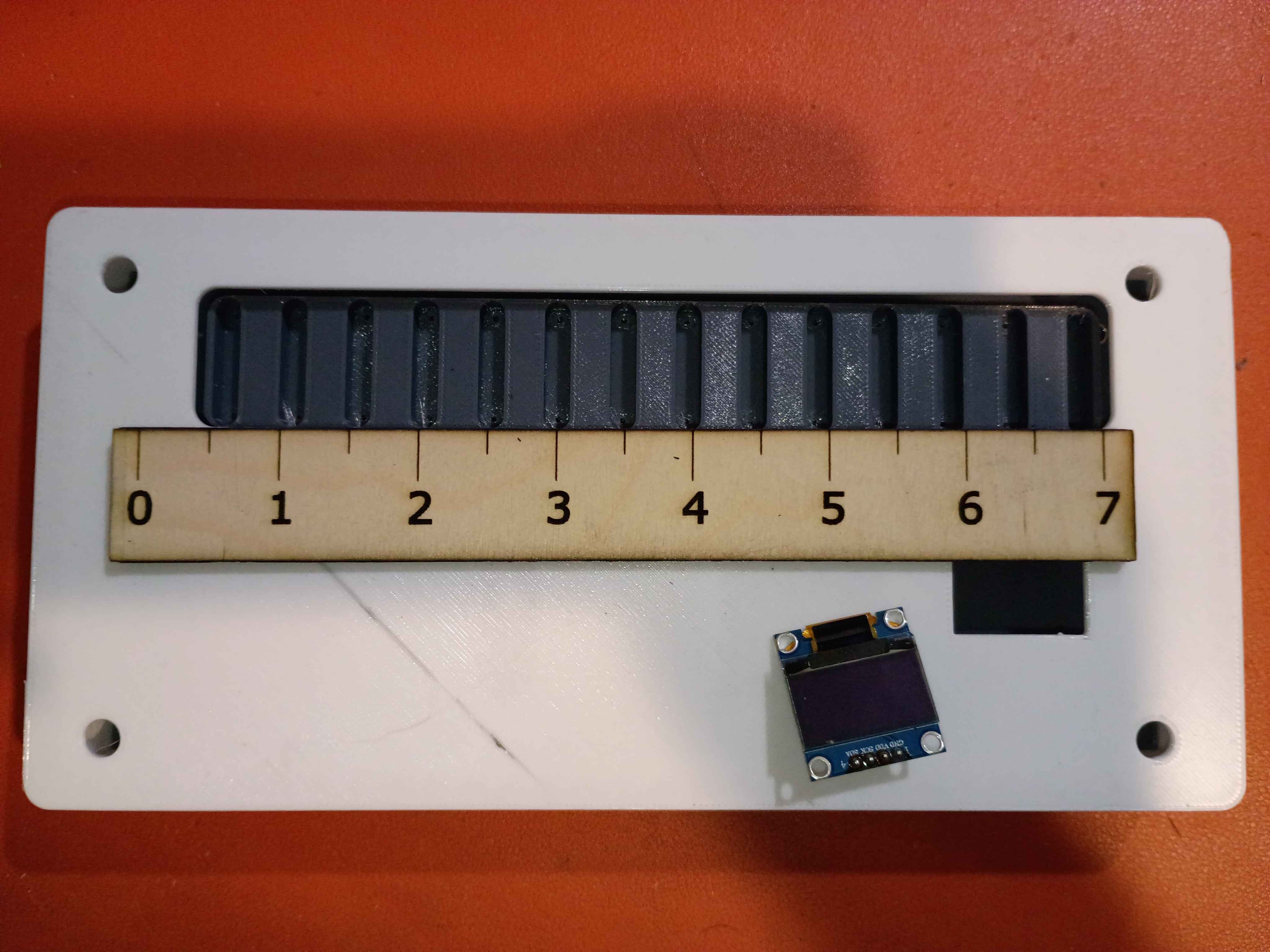
Attached rubber feet to bottom. 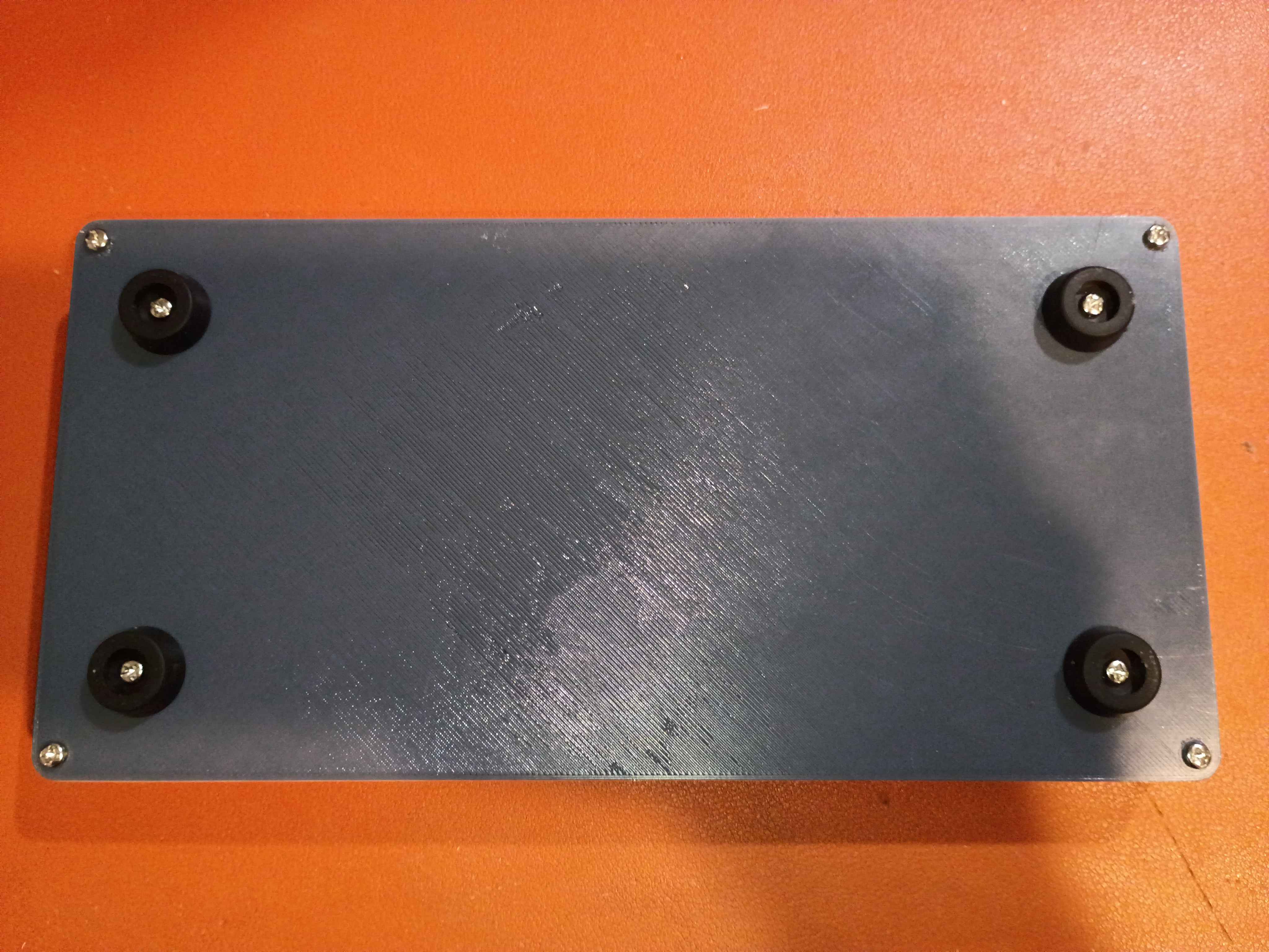
Tested various Ferric Chloride etch-resist options on a scrap piece of copper clad. 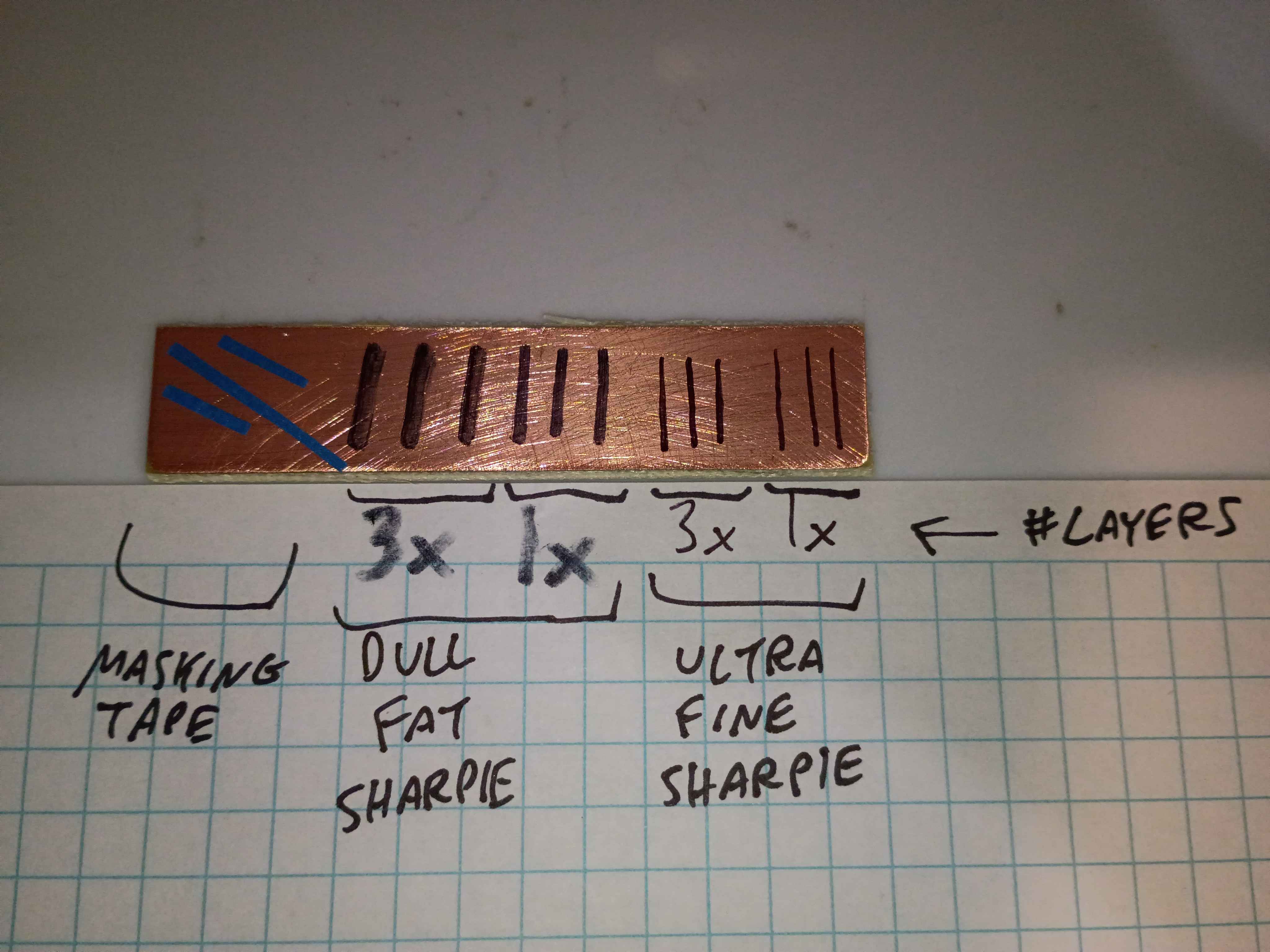
The finest and best solution is multiple coats/layers of the Ultra Fine Sharpie, or masking tape for large rectangular areas. 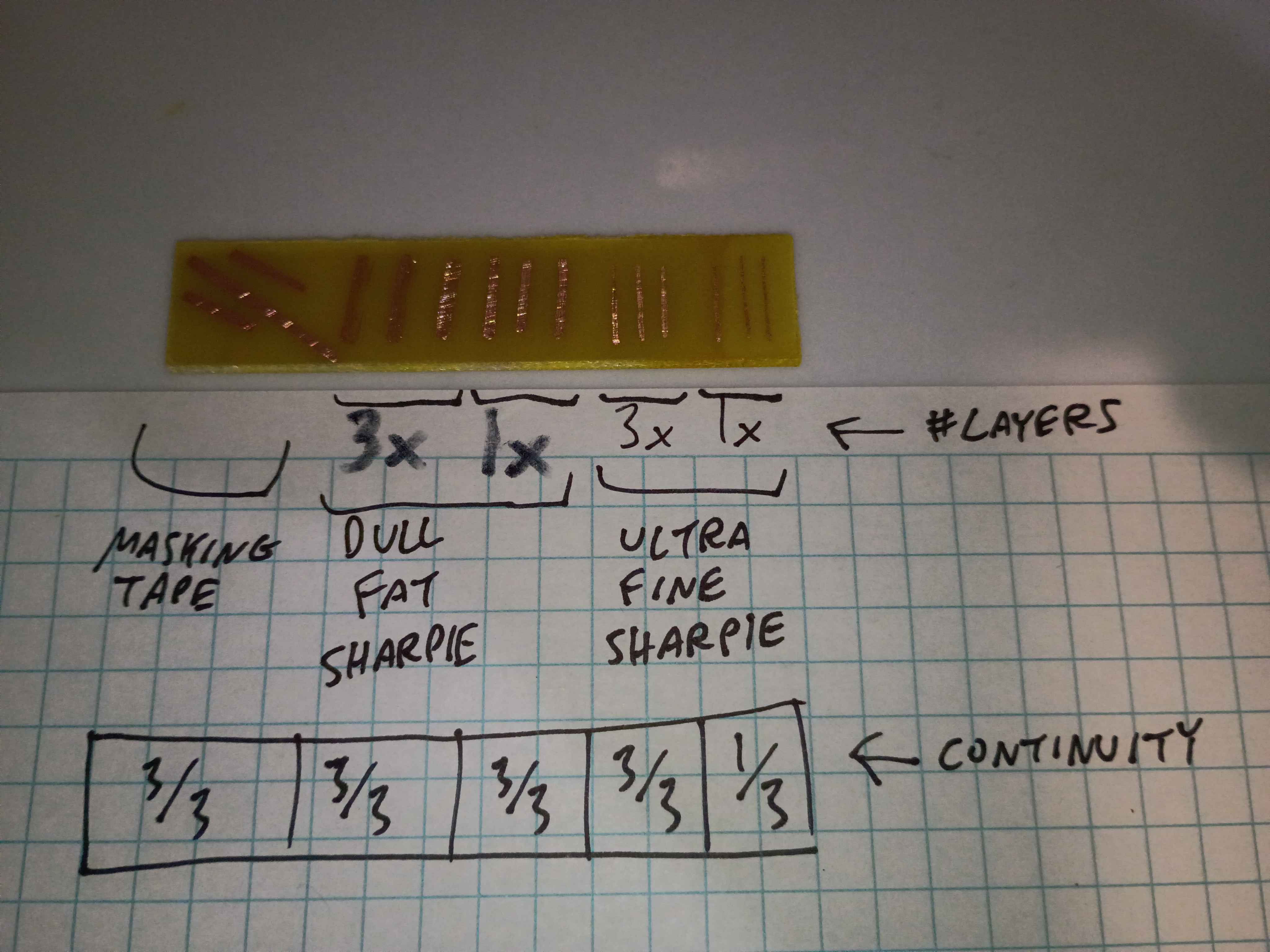
Used these solutions to repair minor issues in the toner-transferred copper mask. 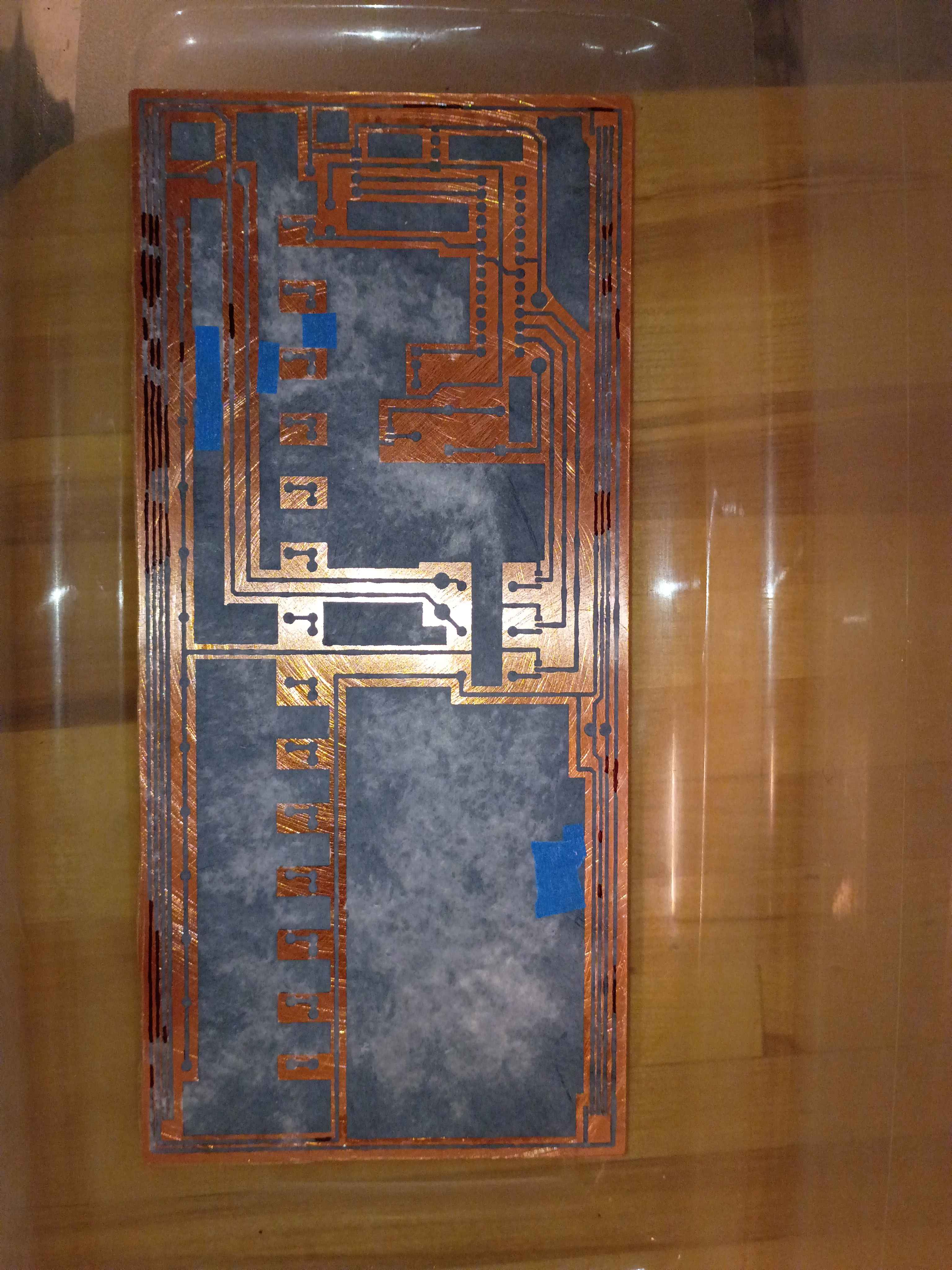
Etched away the copper to reveal the traces. 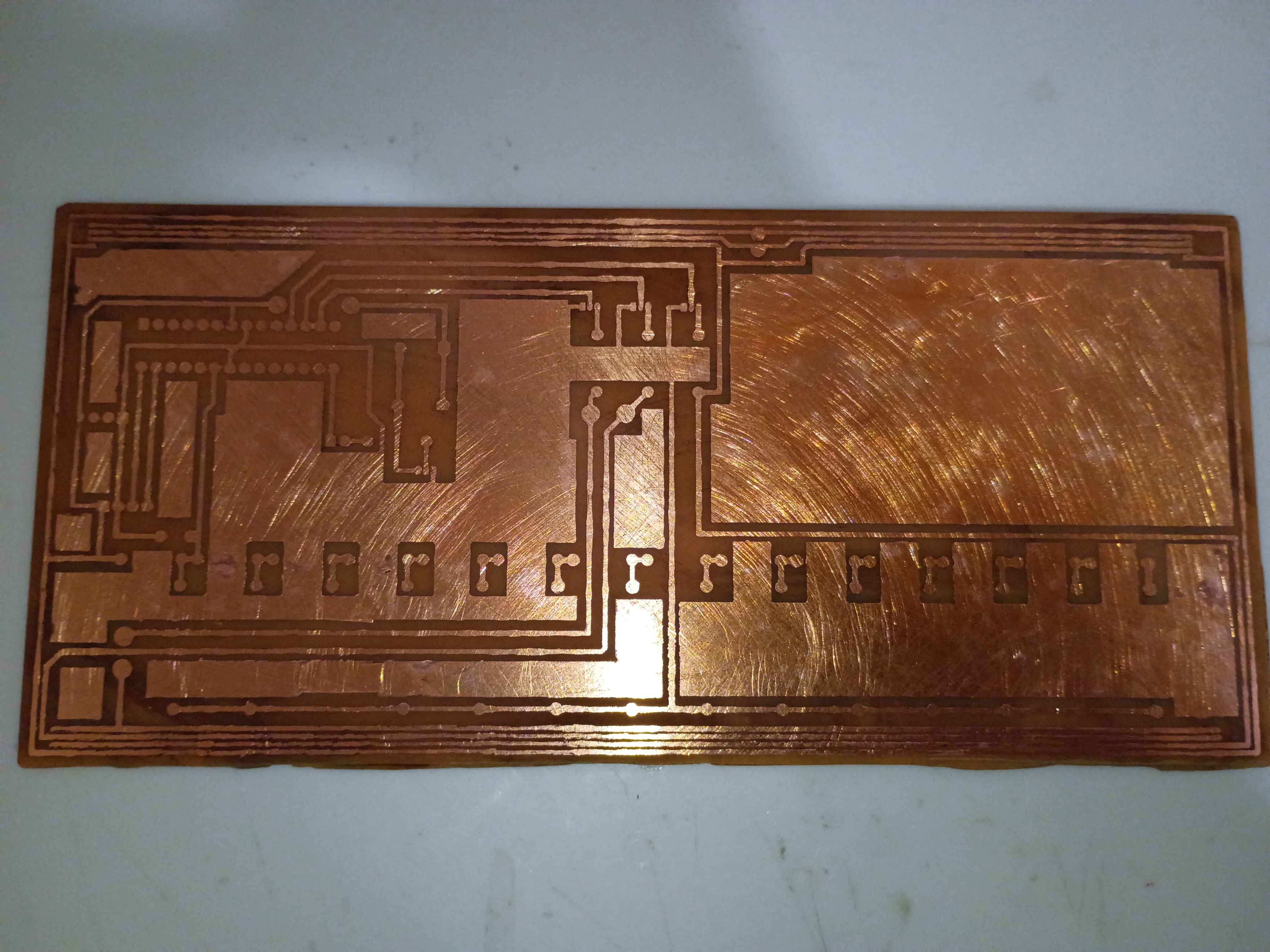
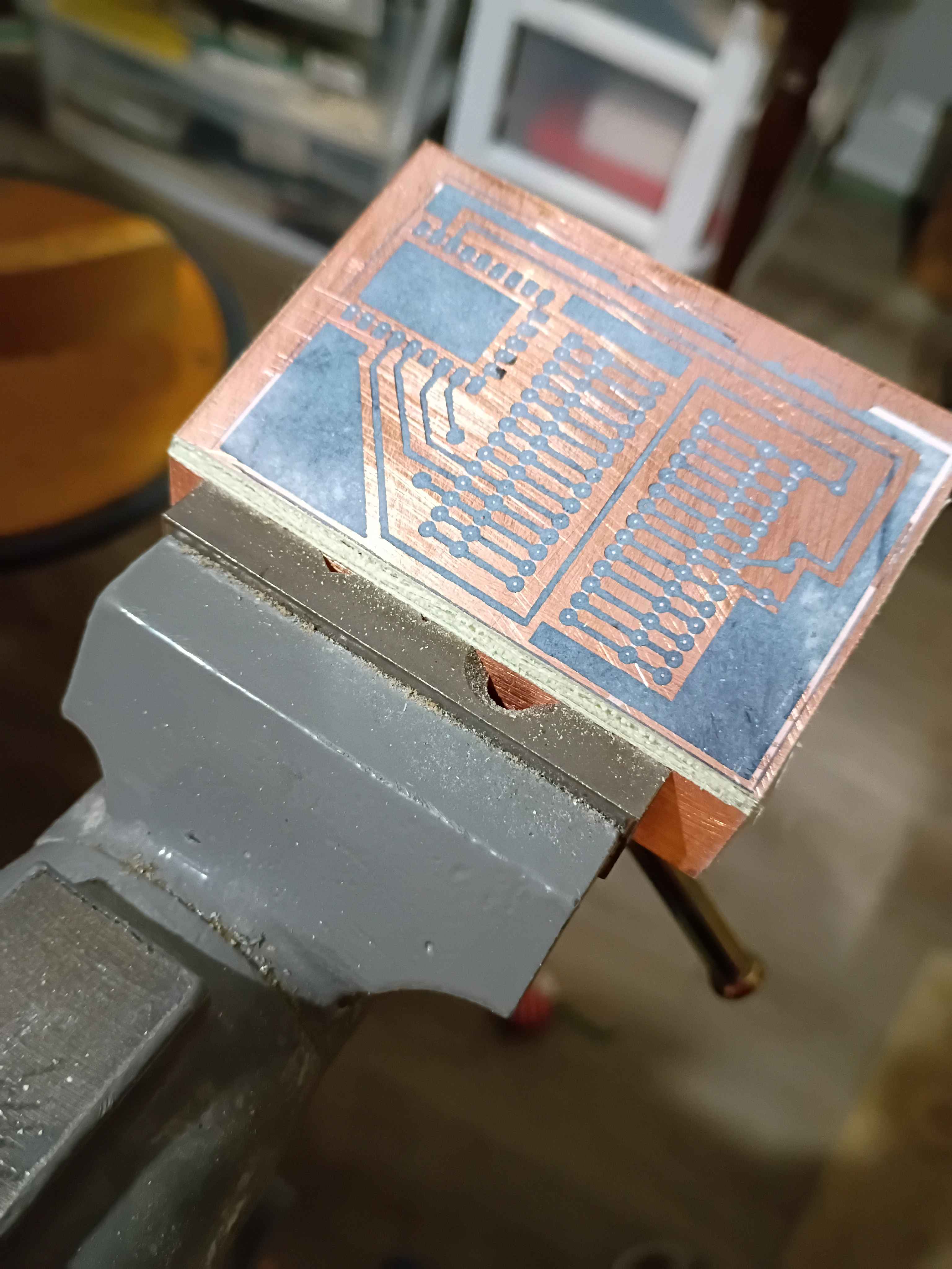
Toner-transferred the copper trace mask on the copper clad board. It actually turned out decently for the size and relative complexity. The edges peeled off a bit, but that always happens for me; I will redraw those areas with Sharpie or masking tape. I also scraped off the lingering bits of paper with a knife. For future reference, I used the iron on max heat, let the board cool briefly before setting it in the water, and let it sit in the water for ~20 minutes before rubbing off most of the paper backing, and 20 more minutes before rubbing off any remaining paper residue. 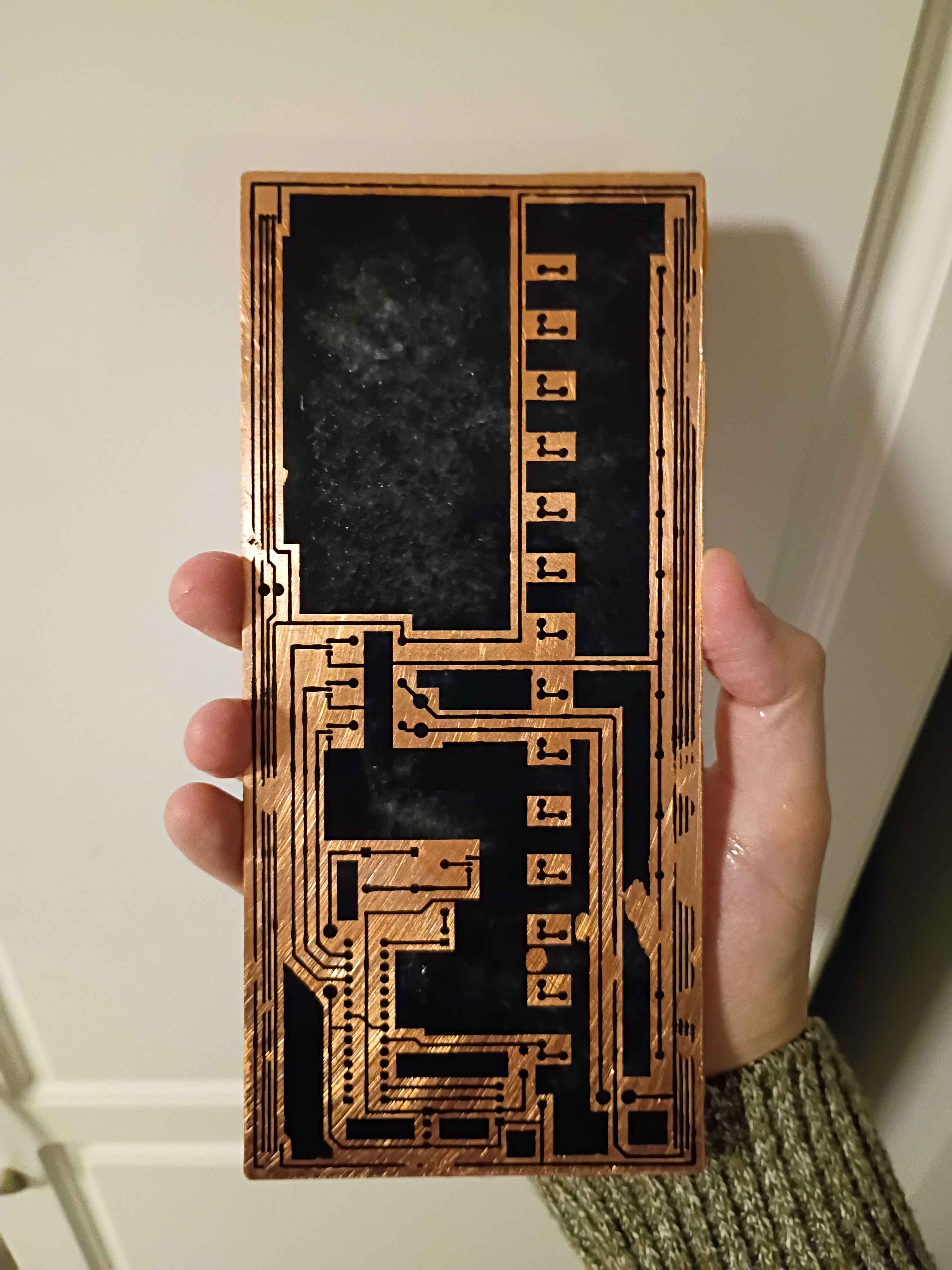
Implemented "!editjournal" command in Mary-Bot to edit an existing journal entry. Date, project & author values are preserved, but text content and uploaded images are replaced completely. Intended to make it easy to fix small grammatical errors or replace pictures. The syntax is: "!editjournal 0094 Revised text content goes here." In fact, this journal entry was created and revised using this command.
Successfully printed the box assembly from PETG. A little bit of warping on the large flat cover piece, though the screws should hold that in place, and a bit of discoloration streak on the top of the main box component, so I may need to sand/paint or cover with a sticker. Everything fits together well. 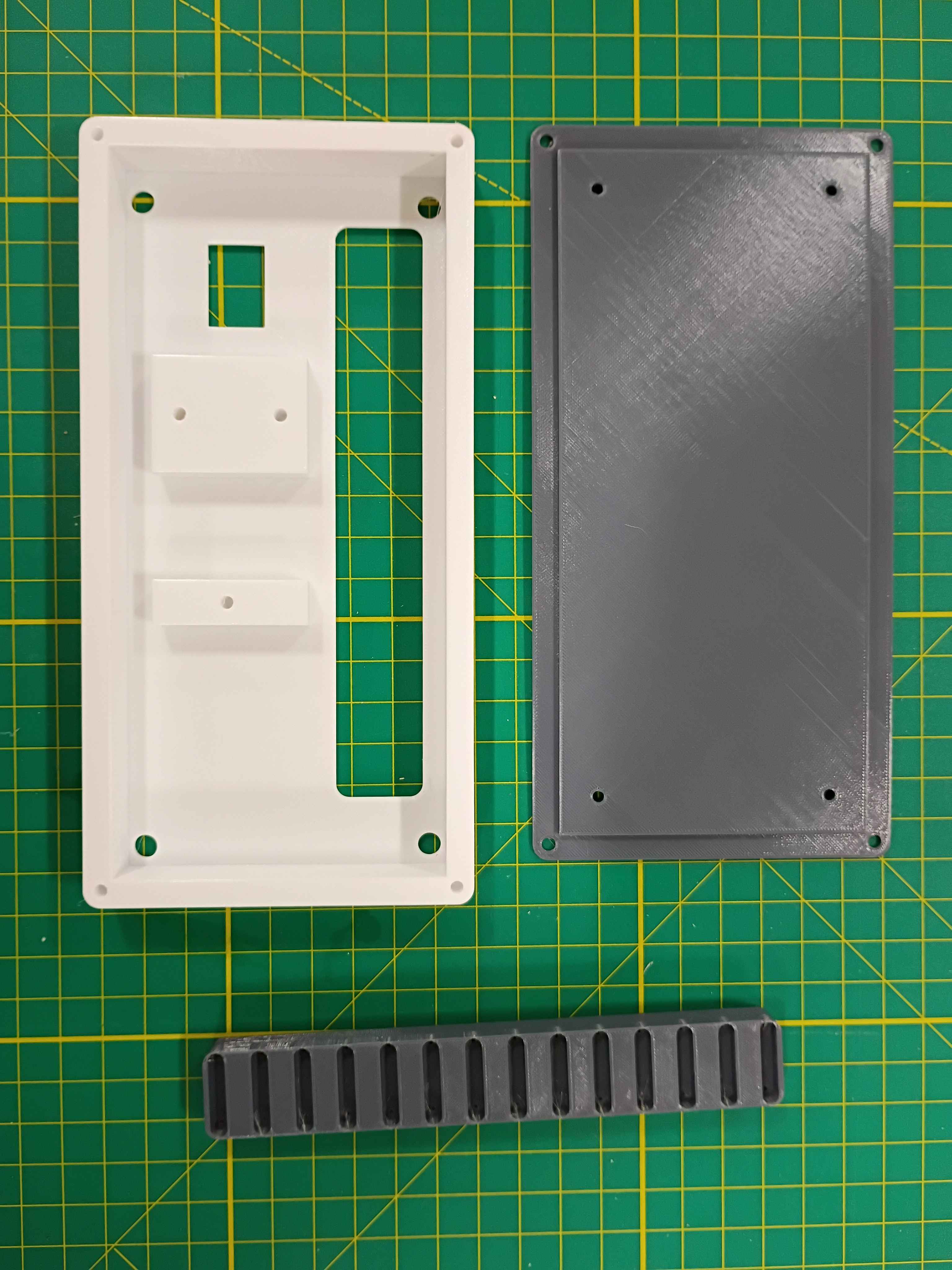
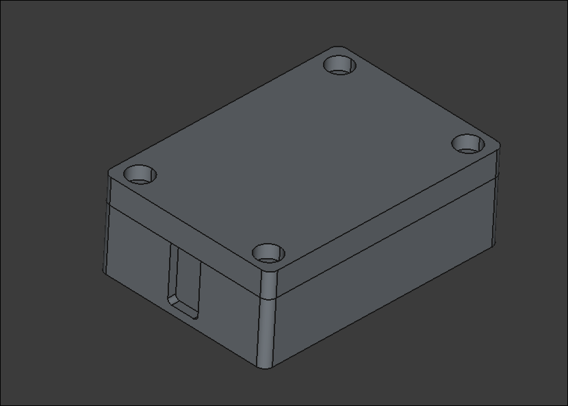
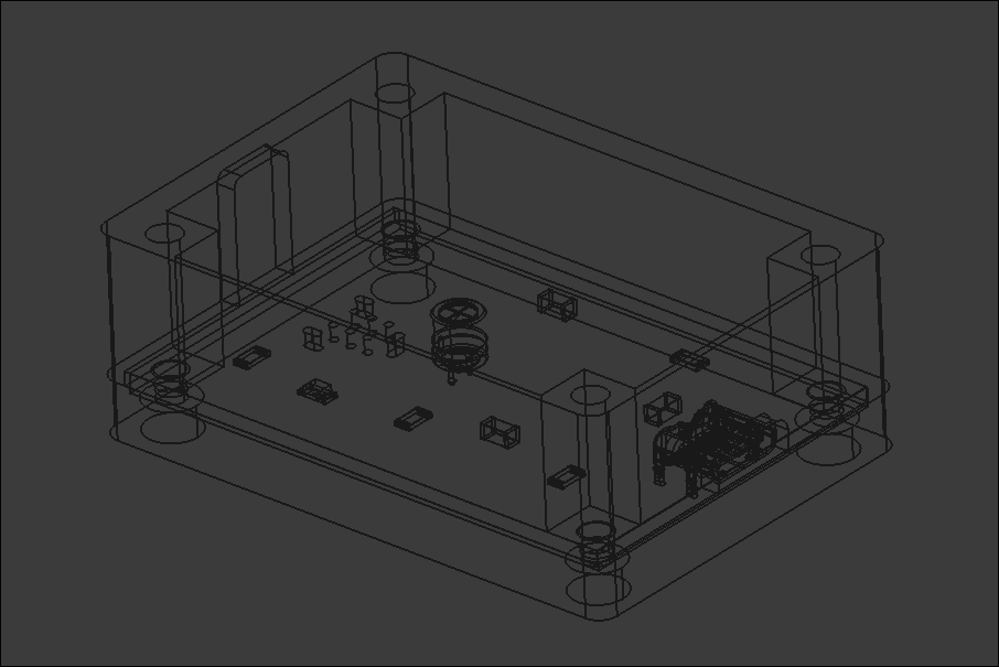
Completed design for a prototype box assembly that should support all the components and the rubber feet I already sourced. Since the part is quite large, it will need to be printed on the machine at work. I will try that tomorrow. I might need to iterate on the main support body at least once to get the depth correct. 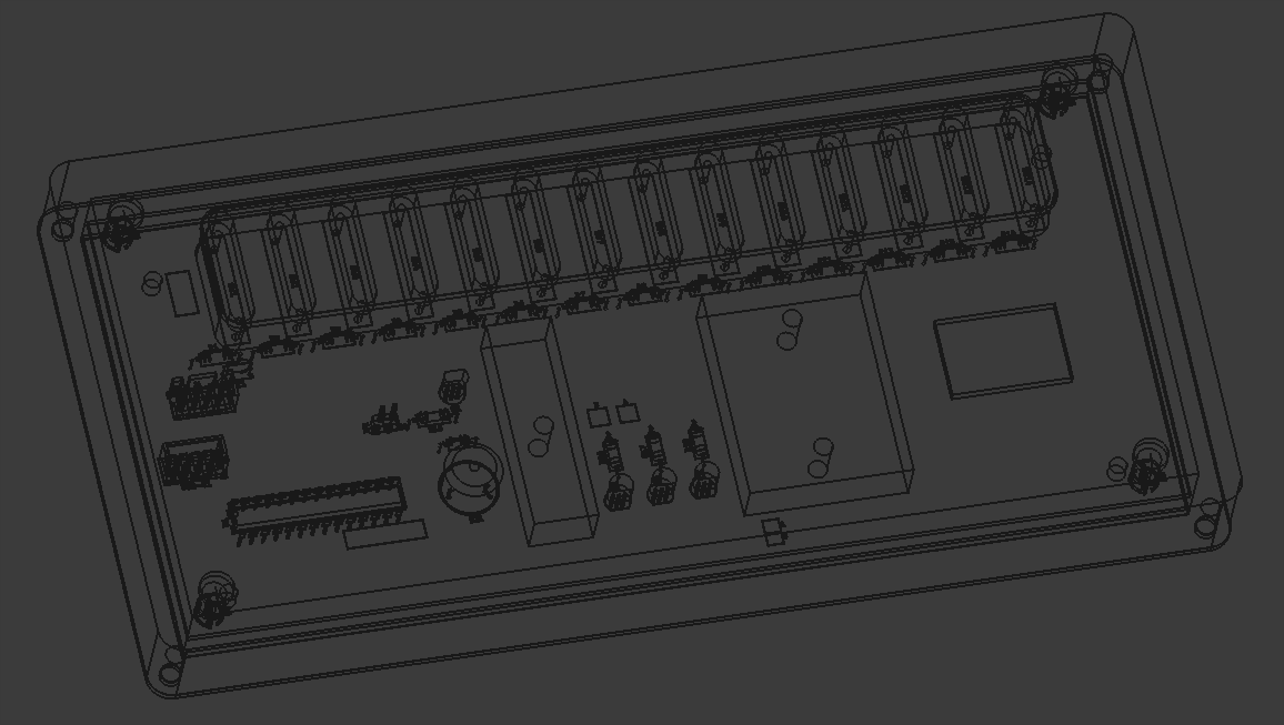
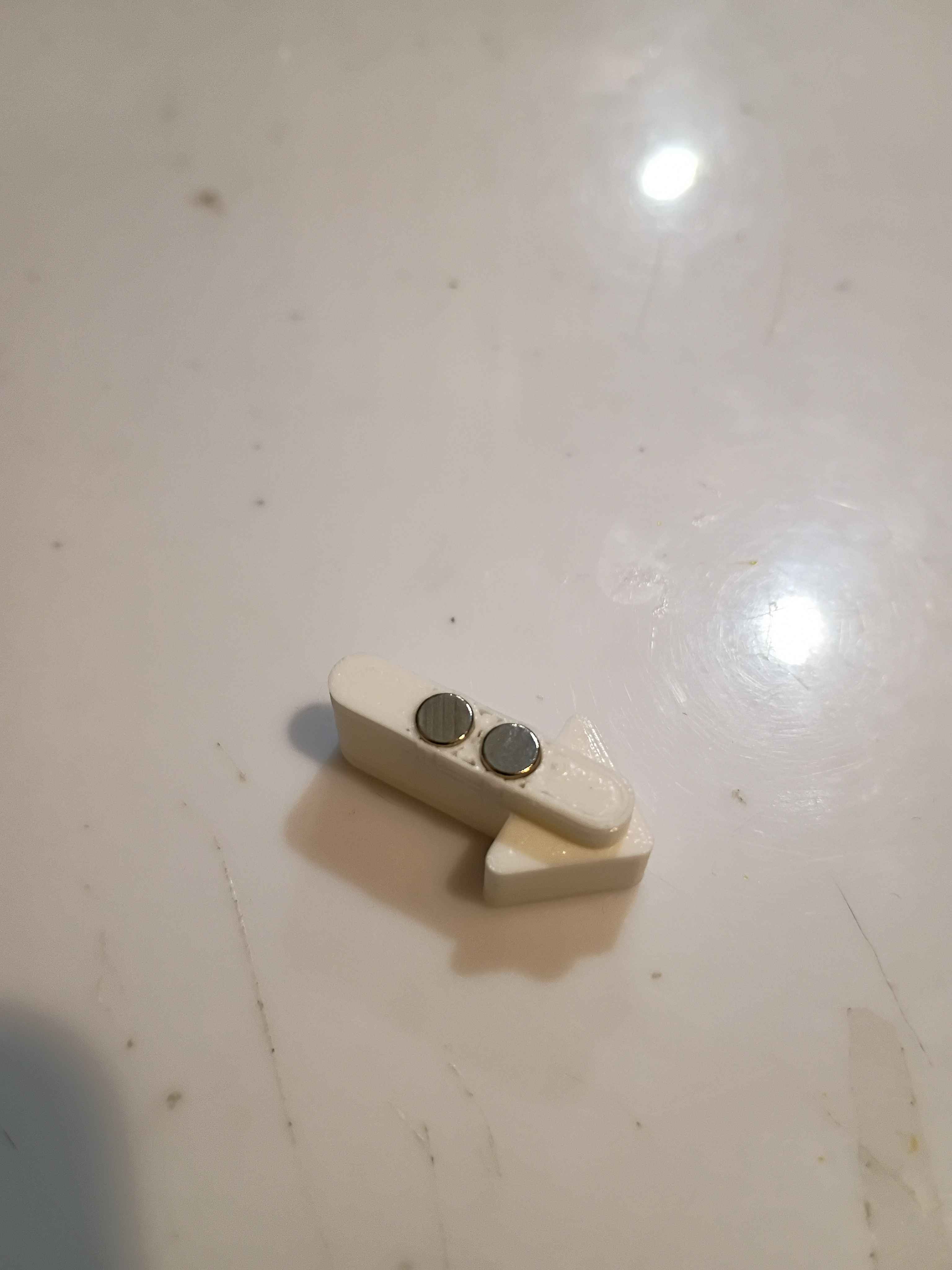
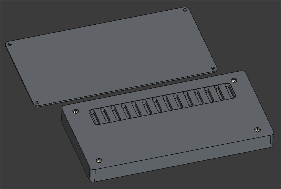
Designed a 3-piece 3D-printed assembly for the project. One component to support the reed switches on the PCB, one box to mount the PCB assembly, and a lid. I still need to add a hole in the top face for the OLED screen. Everything is removably mounted with M3 screws. 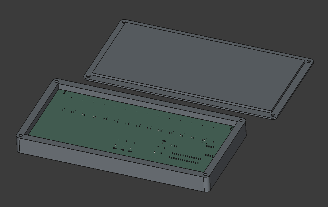
Looking into possibly pivoting away from laser-cut plywood box to a 2-piece 3D-printed box. It would be more robust, reproducible, and suitable for this container, though it will be roughly 230mm wide, which is approaching the maximum for the Prusa MK3S that I will print it on, which may pose problems.
Finalized design of top and front/back of manipulative box. Still considering options for the bottom that are easy to remove for access to repair and replace components.
Continued design of box lid, following the same ridged perimeter profile that worked so well on 03008.
Began the CAD for the box. Imported the PCB STEP file from Kicad to ensure a proper fit.
Added usage instructions and photos to the documentation linked by the product URL.
Trimmed roughly a quarter inch off the end of the ballscrew to make the entire Y-axis motion assembly fit in the frame interior (barely). Installed the stepper motor bracket in the proper location and then installed the stepper itself. Determined that 18mm of shimming will be required below the ballscrew support blocks. I have various aluminum stock thicknesses that together stack up to that value, and I can cut and drill those this week. 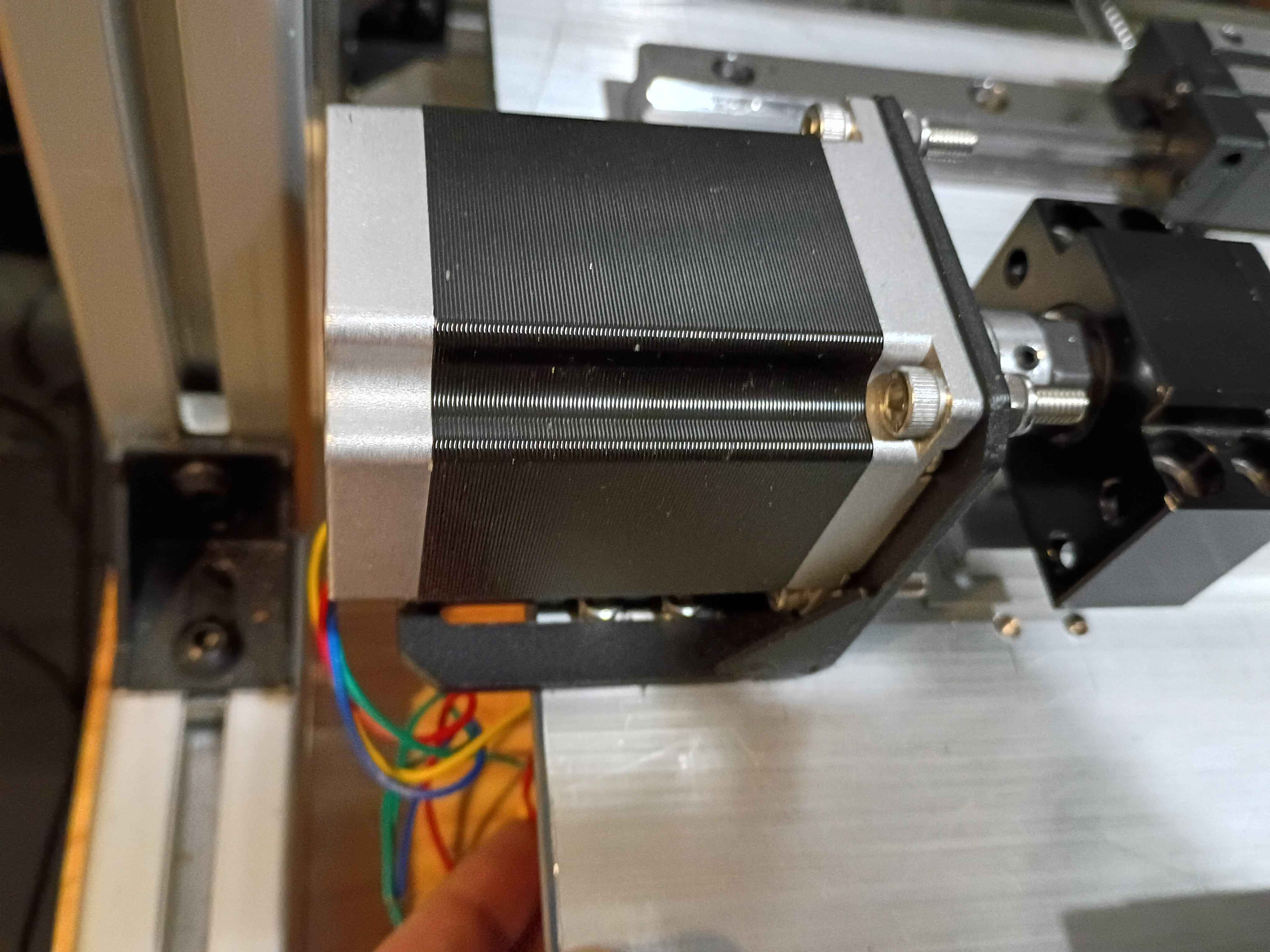
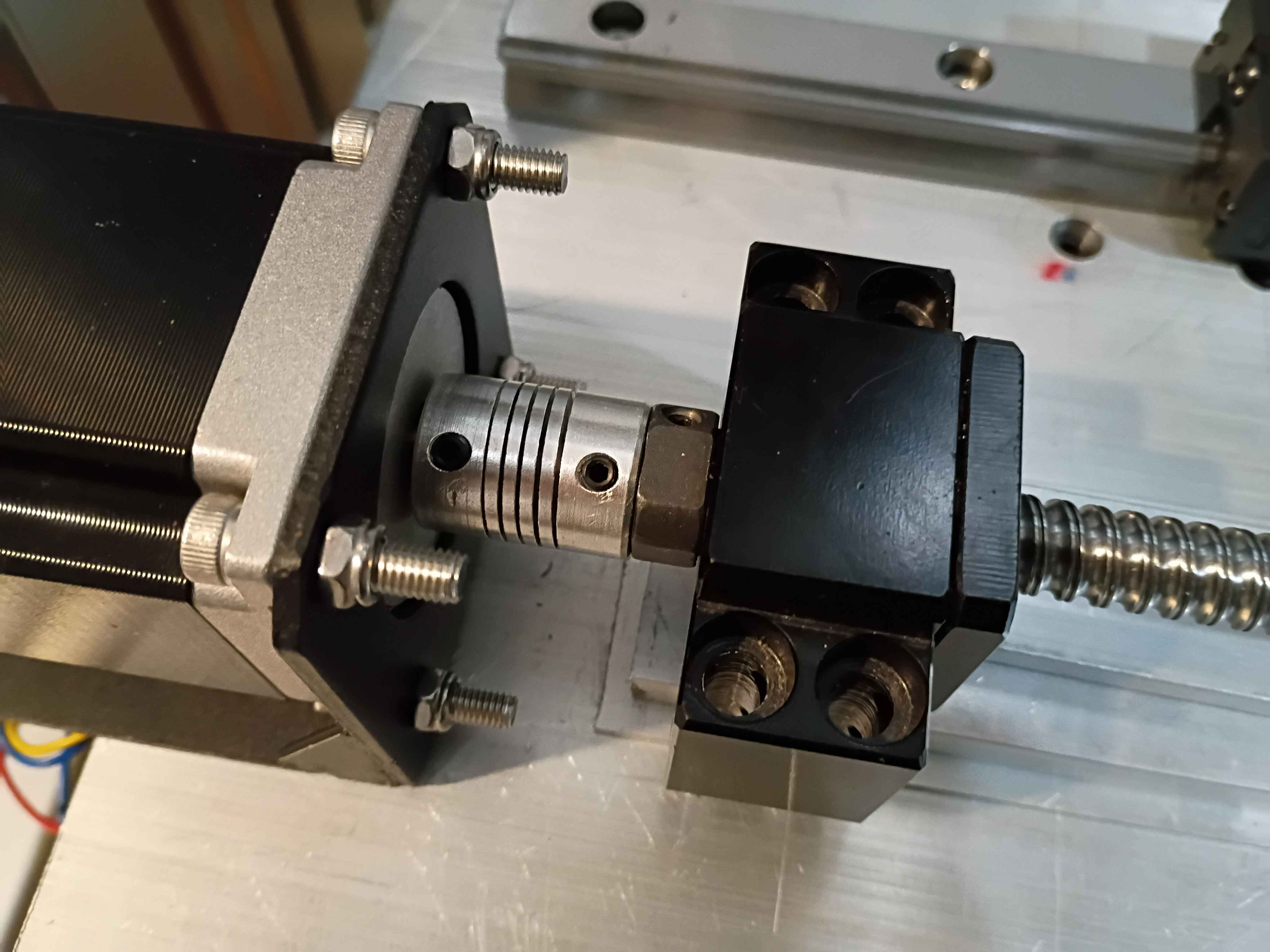
Calculated, measured, marked out, drilled and tapped holes for the Y-axis motion control on the X gantry plate. Installed the linear rails. Because space is tighter than I anticipated, I'll need to saw off a bit from the ballscrew and possibly even some from the drive shaft on the stepper. Not ideal but it should work. I'll also need a different stack of spacers between the ballscrew follower thingamajig and the XY gantry plate since the stepper mount is different, again since space is so tight. 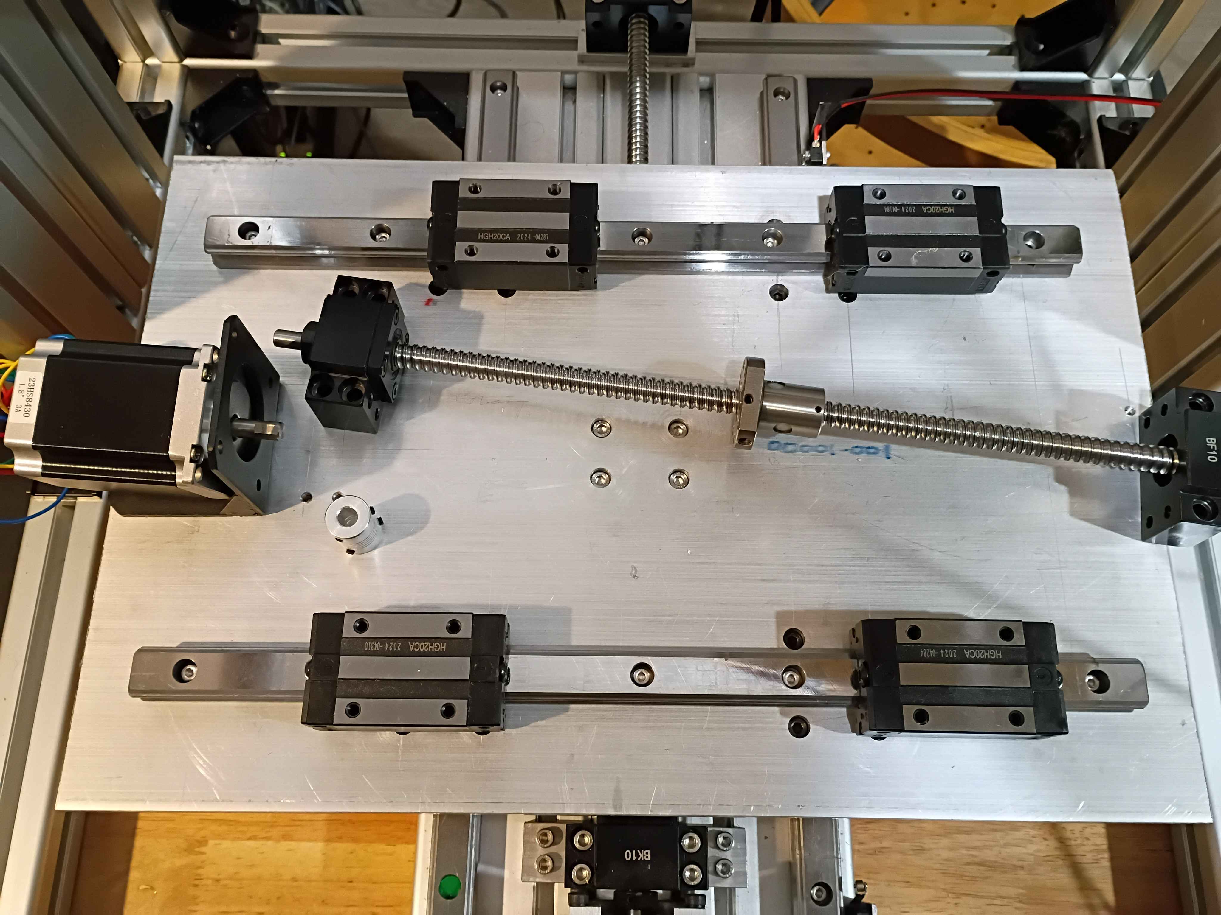
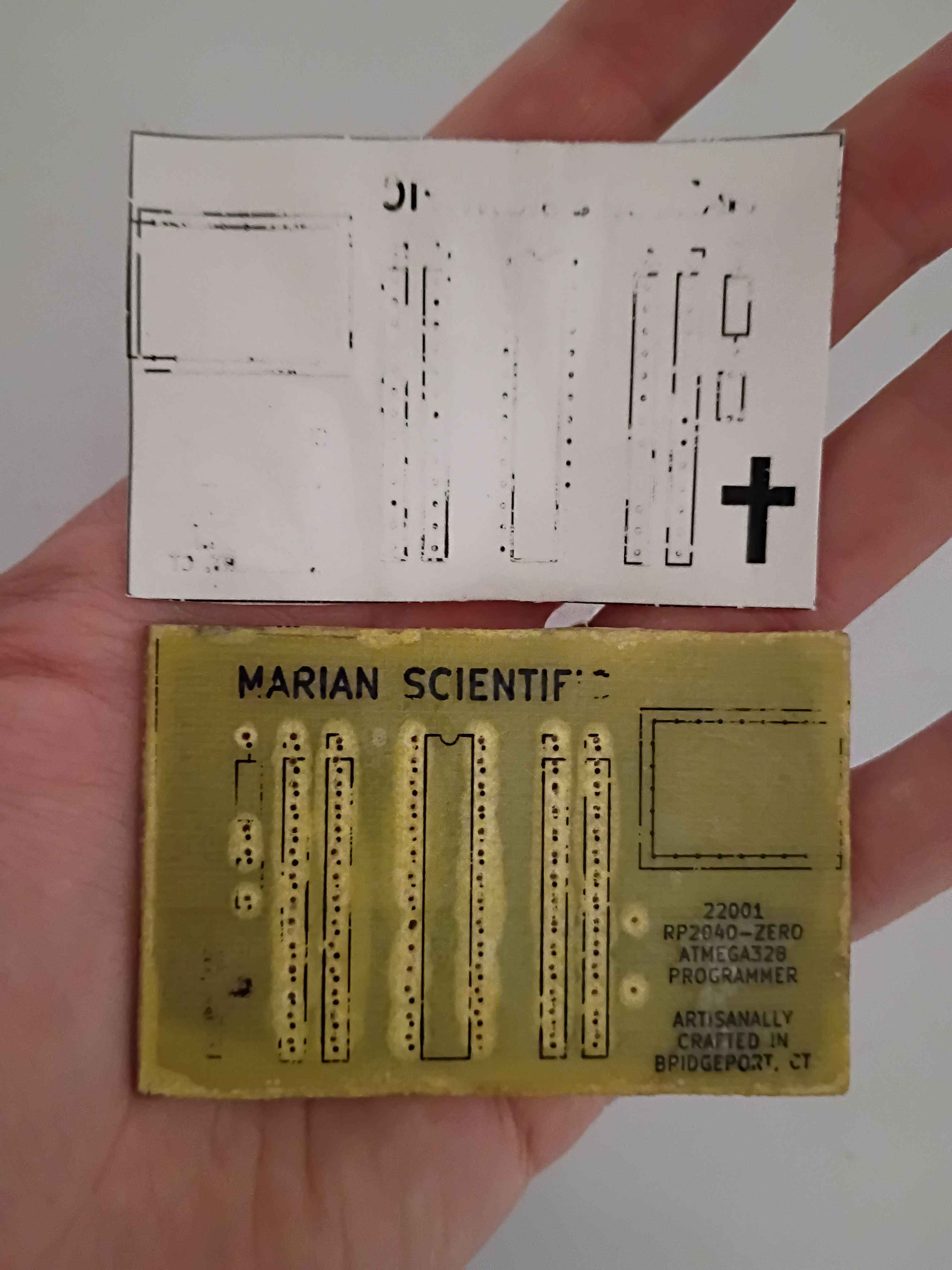
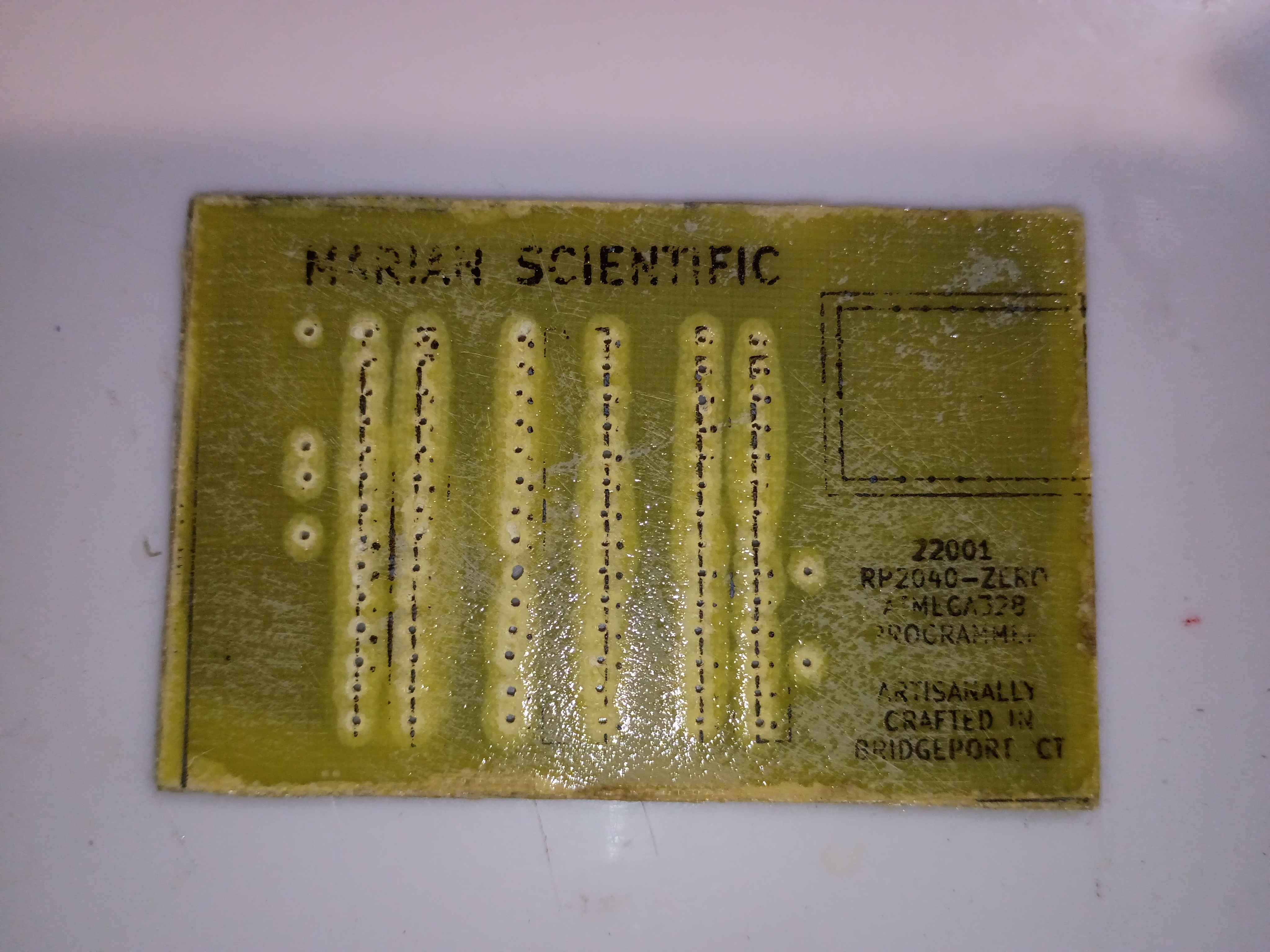
Set up automatic redirect from https://www.marian-scientific.org/22001 to the corresponding folder of the GitHub project repository. Also updated the code and documentation to match.
Completed fabrication of serial number 002 and shipped to our sister facility for future product development. See video of it working during QC testing. it does look pretty snazzy. 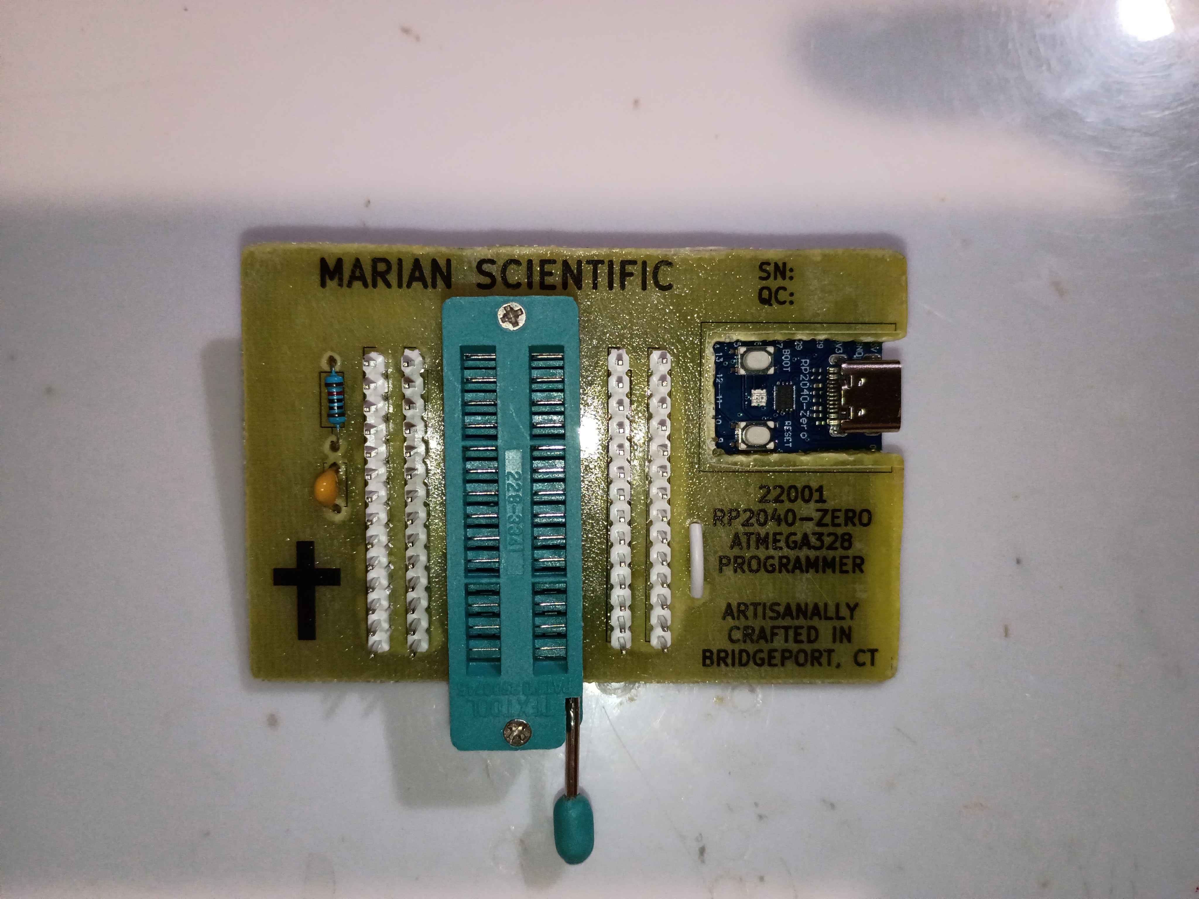
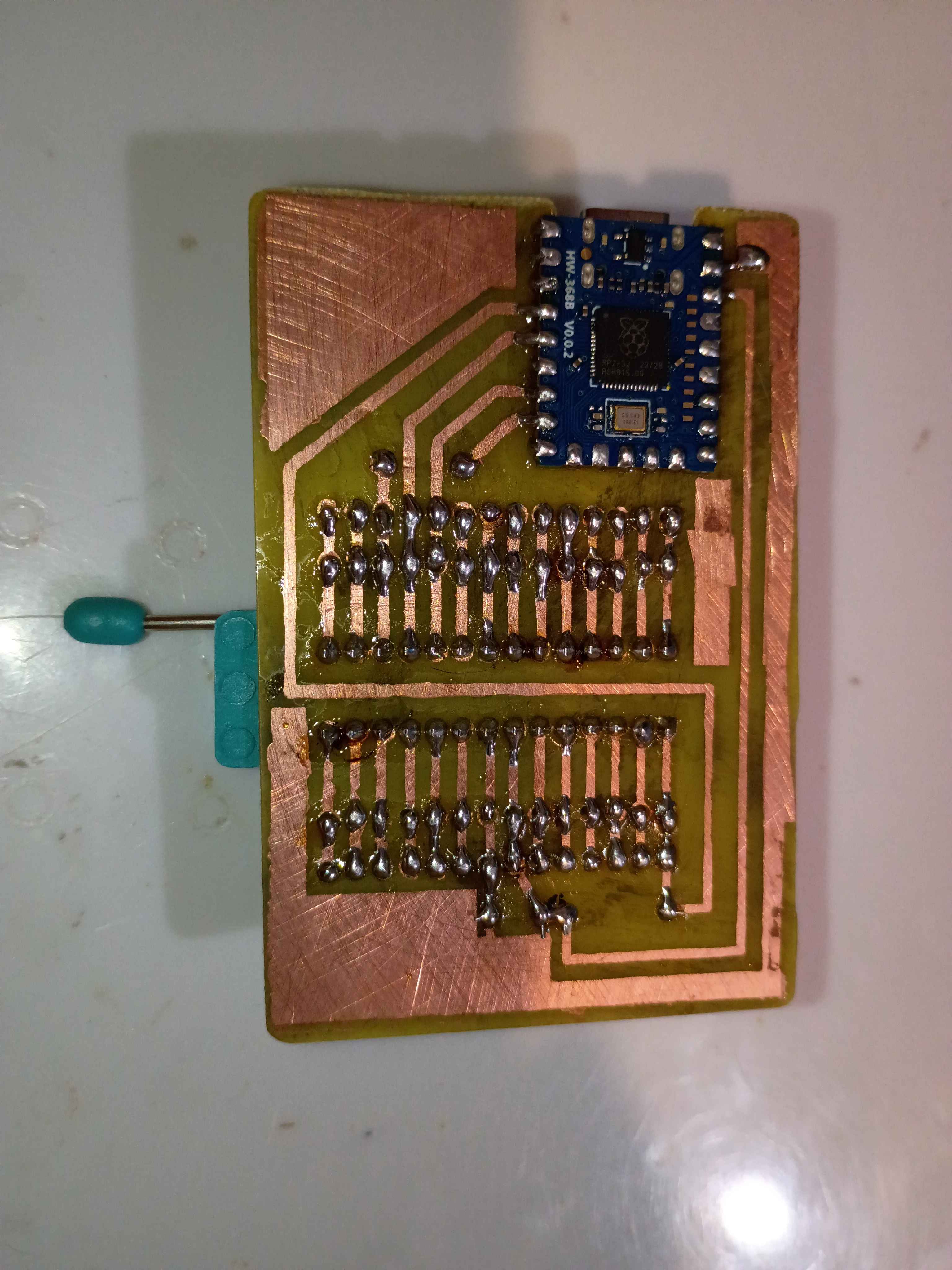
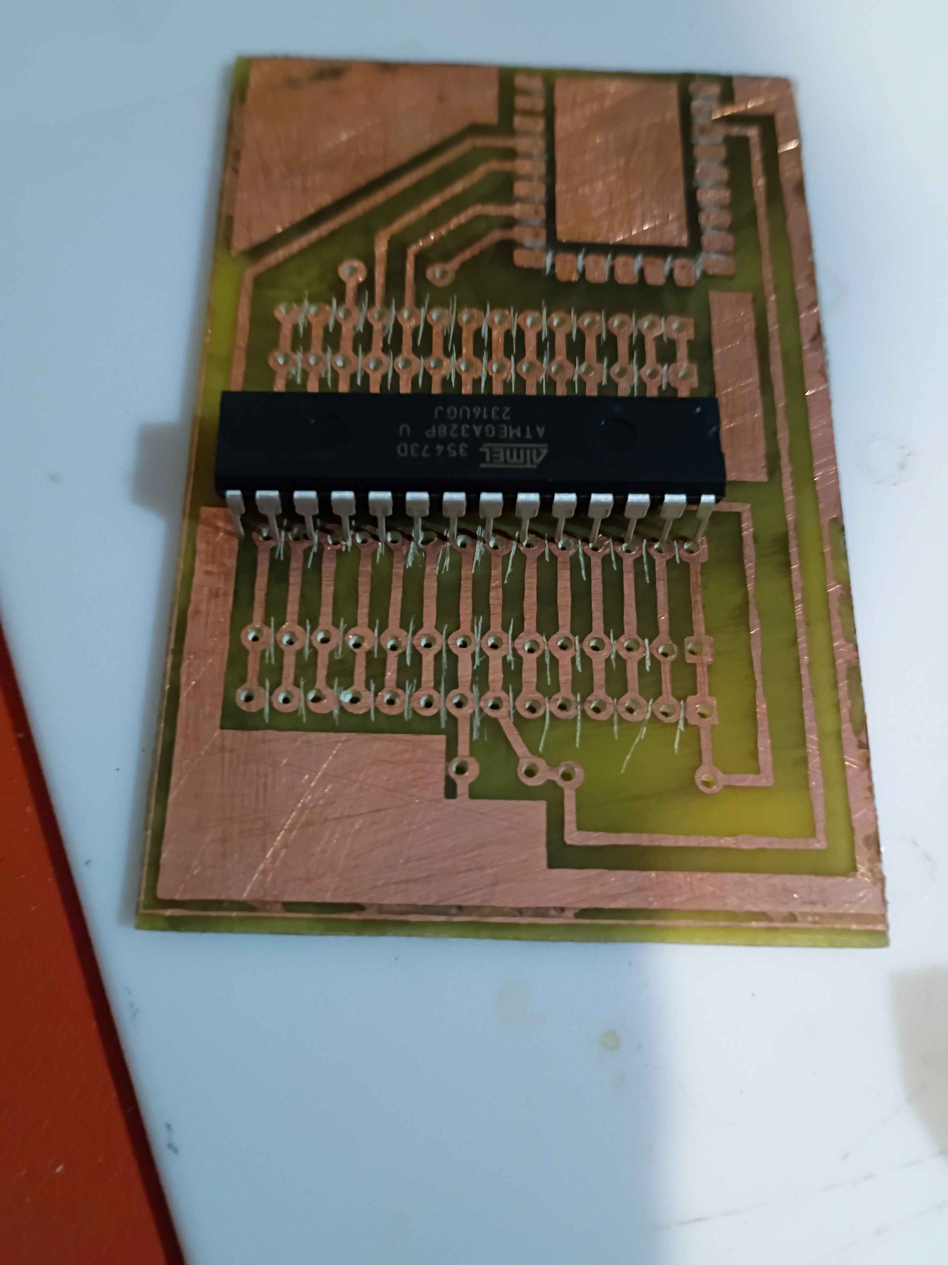
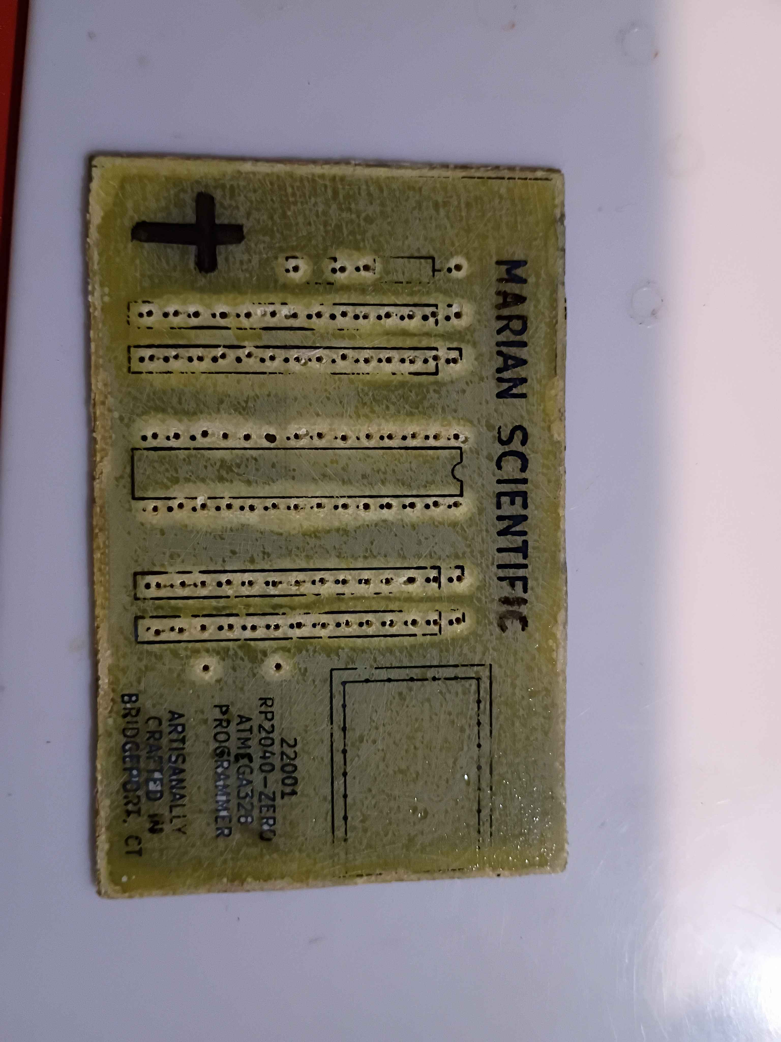
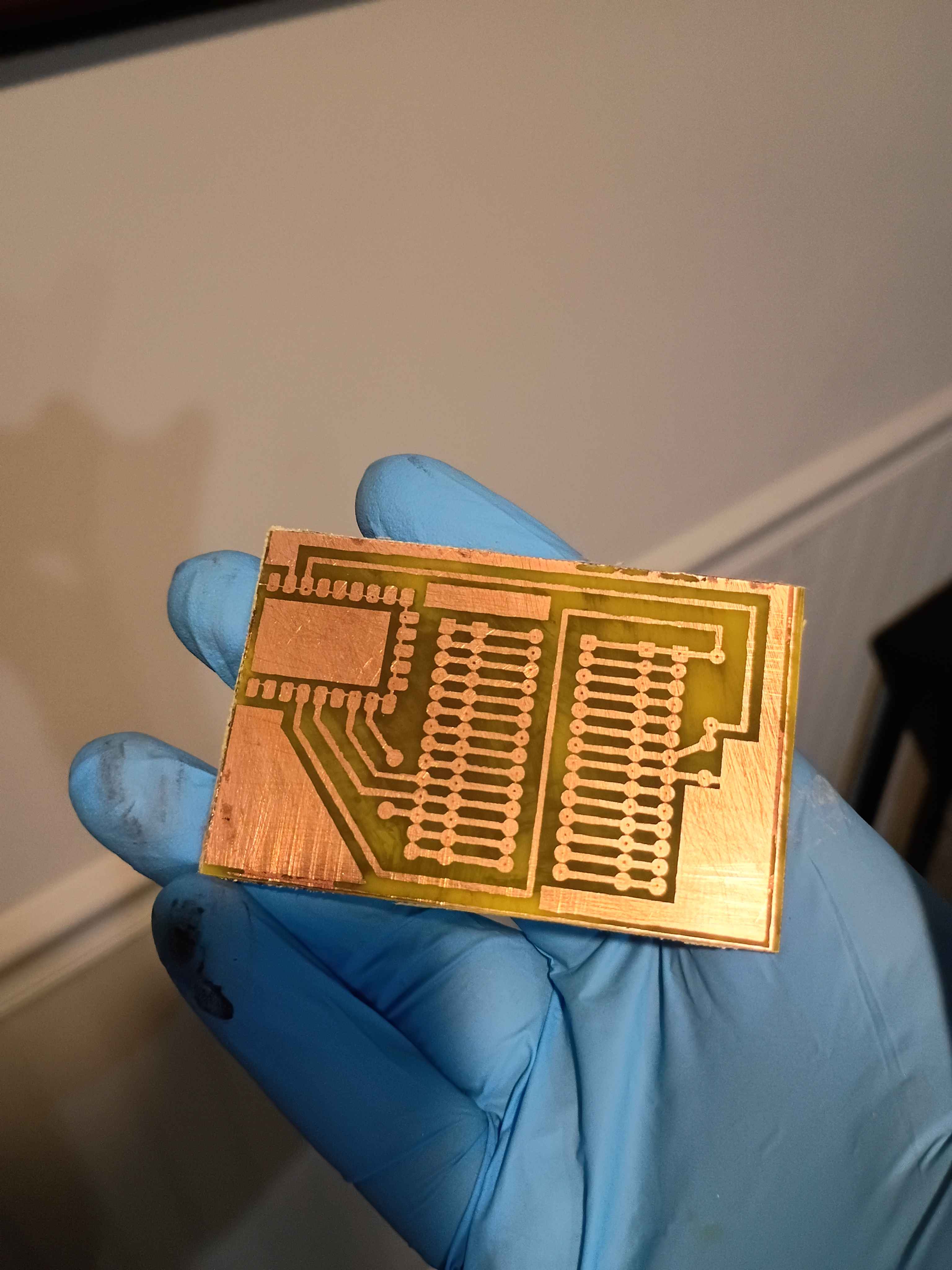
Attempting to make an improved version to provide for internal R&D efforts. Updated the PCB design to improve the text spacing on the F.Silkscreen and add a spot for serialization. Etched another PCB and drilled thru holes, slightly nicer than the previous one in a few different ways. Attempted in vain to toner transfer the silkscreen onto the front face for the final time. Decided to just use a sticker for the foreseeable future, as it's not worth the effort for toner, and it's less robust anyway. Just waiting on some ZIF sockets before I can assemble. 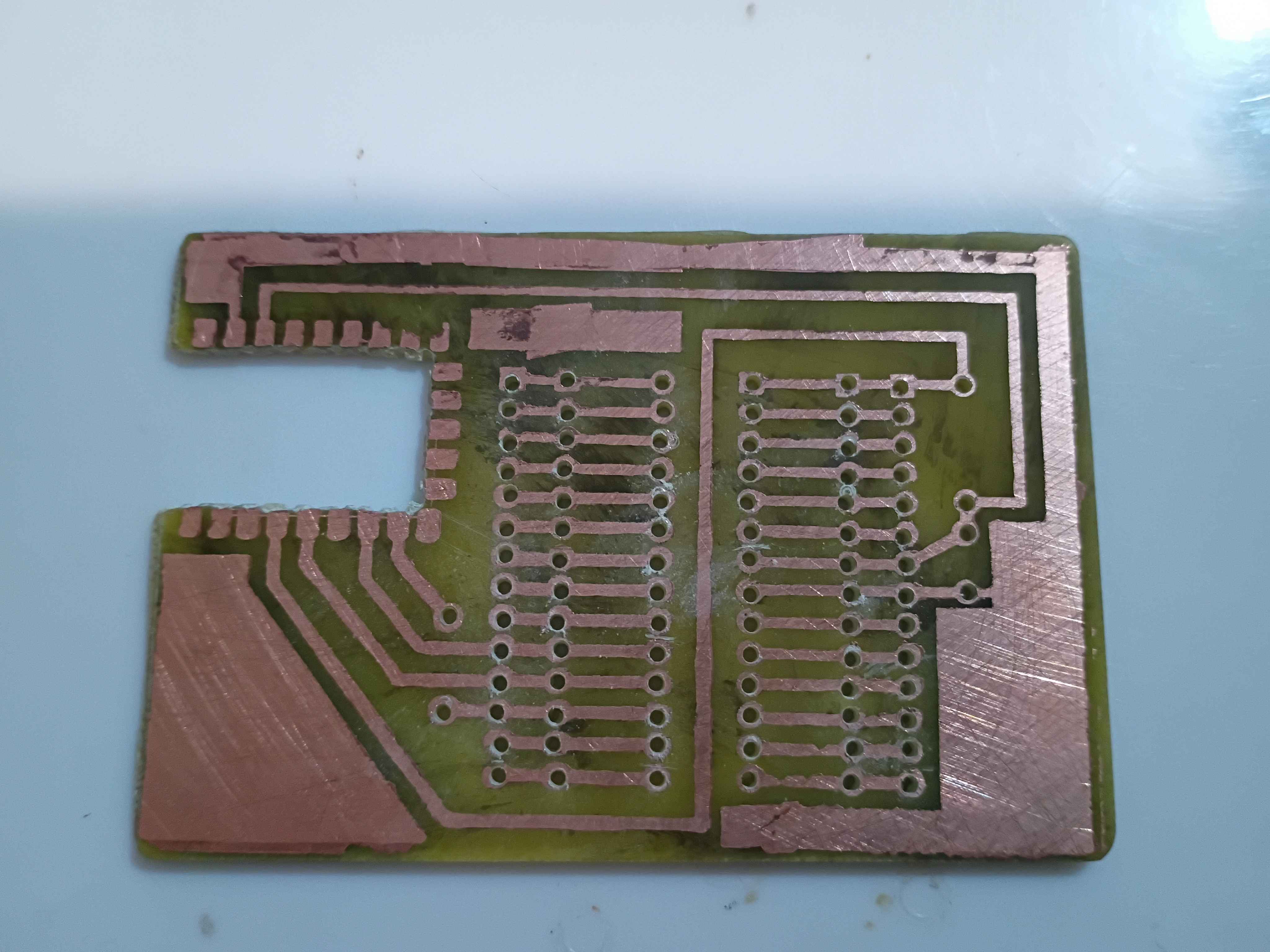
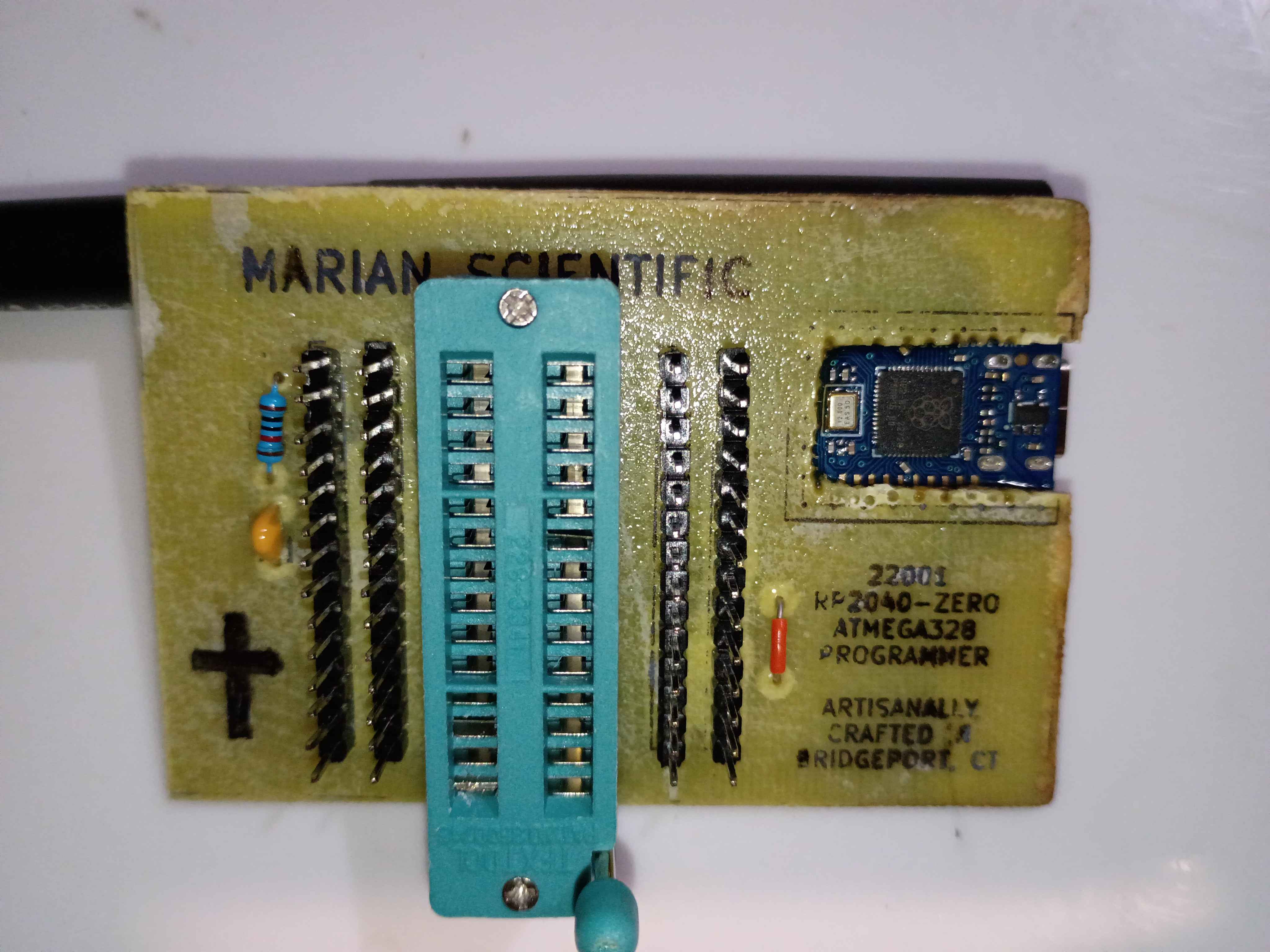
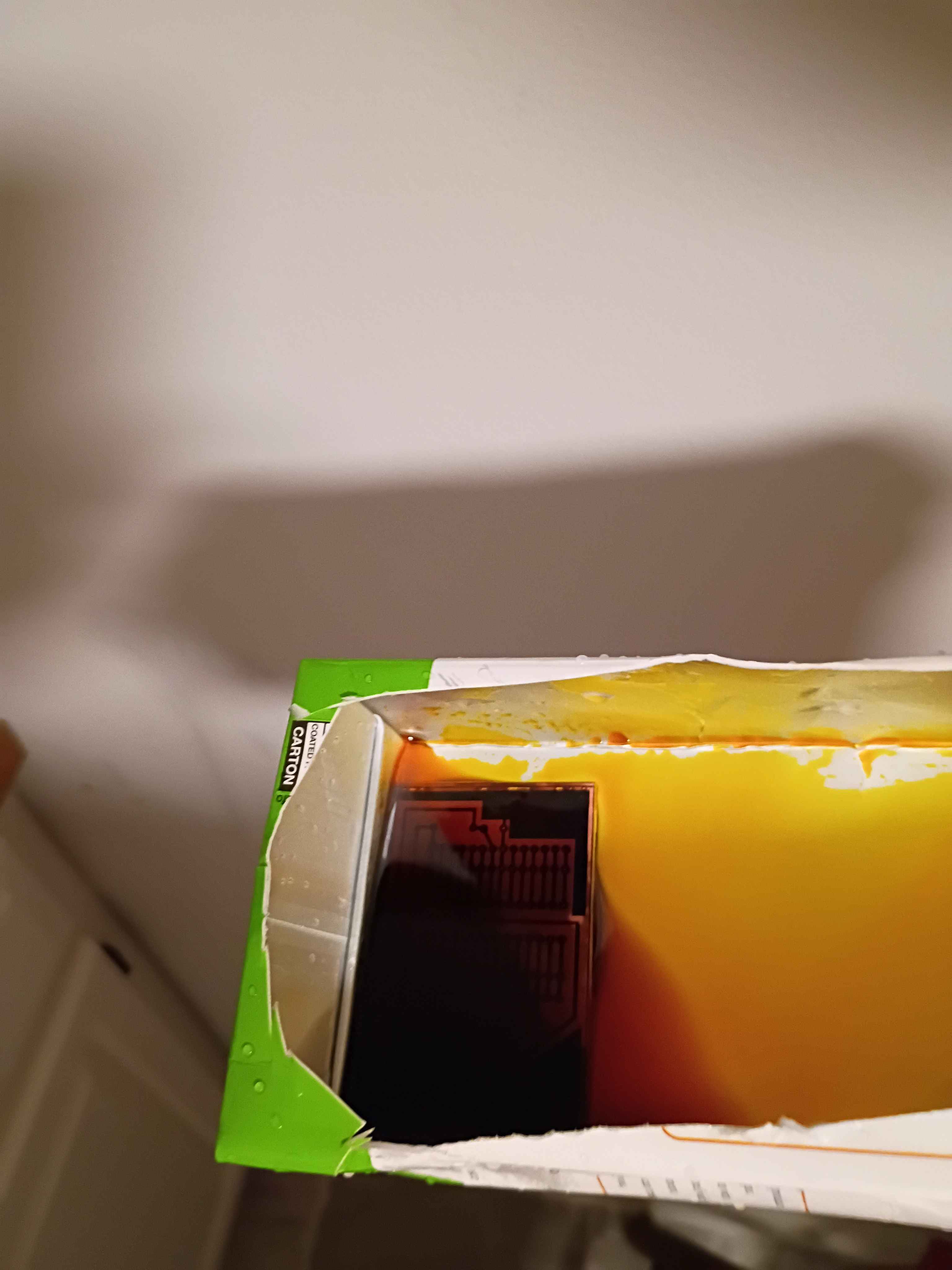
Yesterday, I burned a bootloader on the atmega328P chip, which is now removed from the board shown below. 
I re-soldered the RP2040-Zero board right-side-up, but the programmer still wasn't working. After a shameful 2 hours of debugging, I finally realized I must have fried some magic pixie gems inside the RP2040 by soldering it and running it the wrong way around, so I popped a new one in and it worked a treat. Project complete! See video of it working. If I make another one of these, I will try to do the toner transfer better. It might even warrant an investigation into the heat and pressure levels that give the best results. 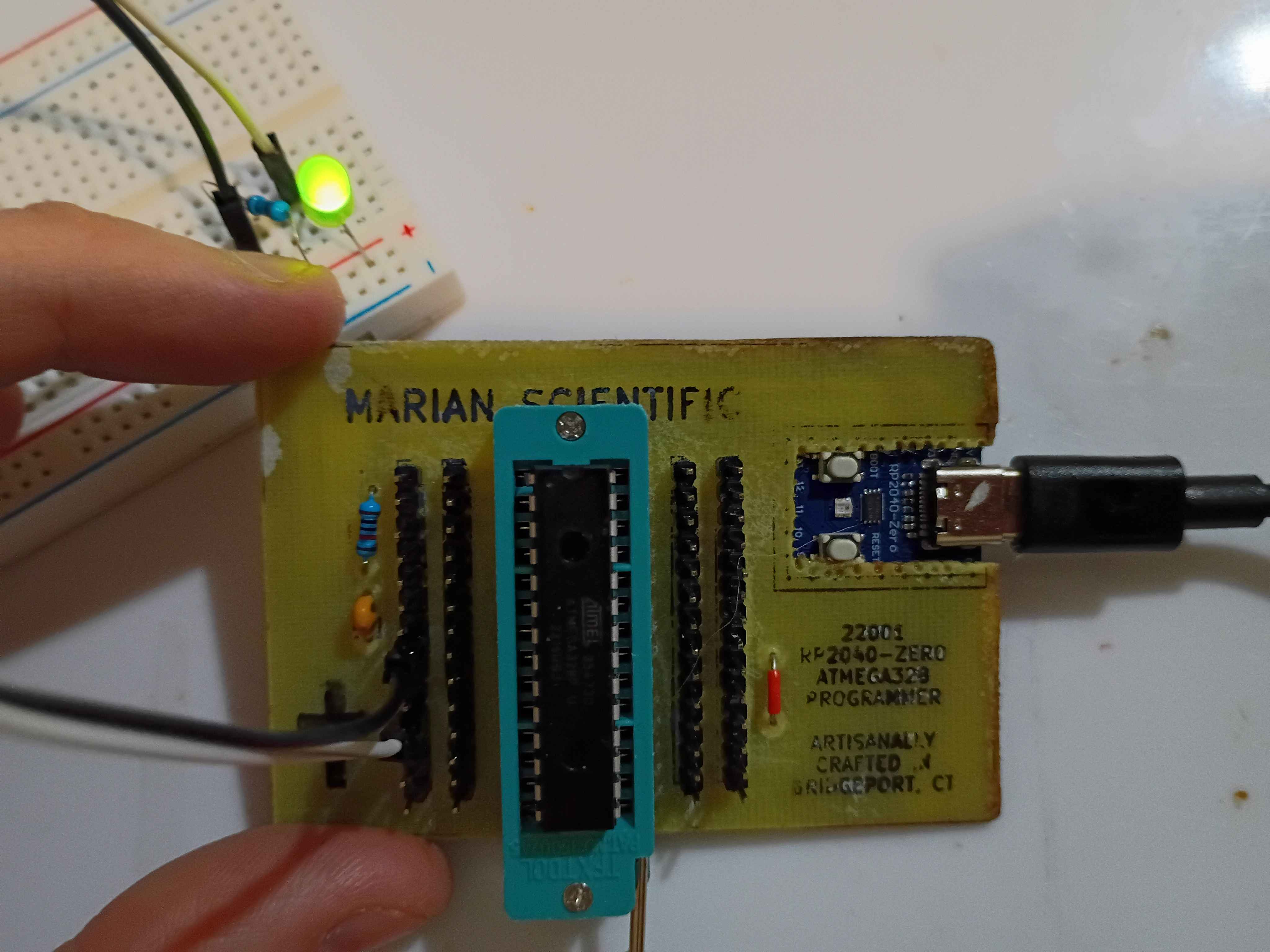
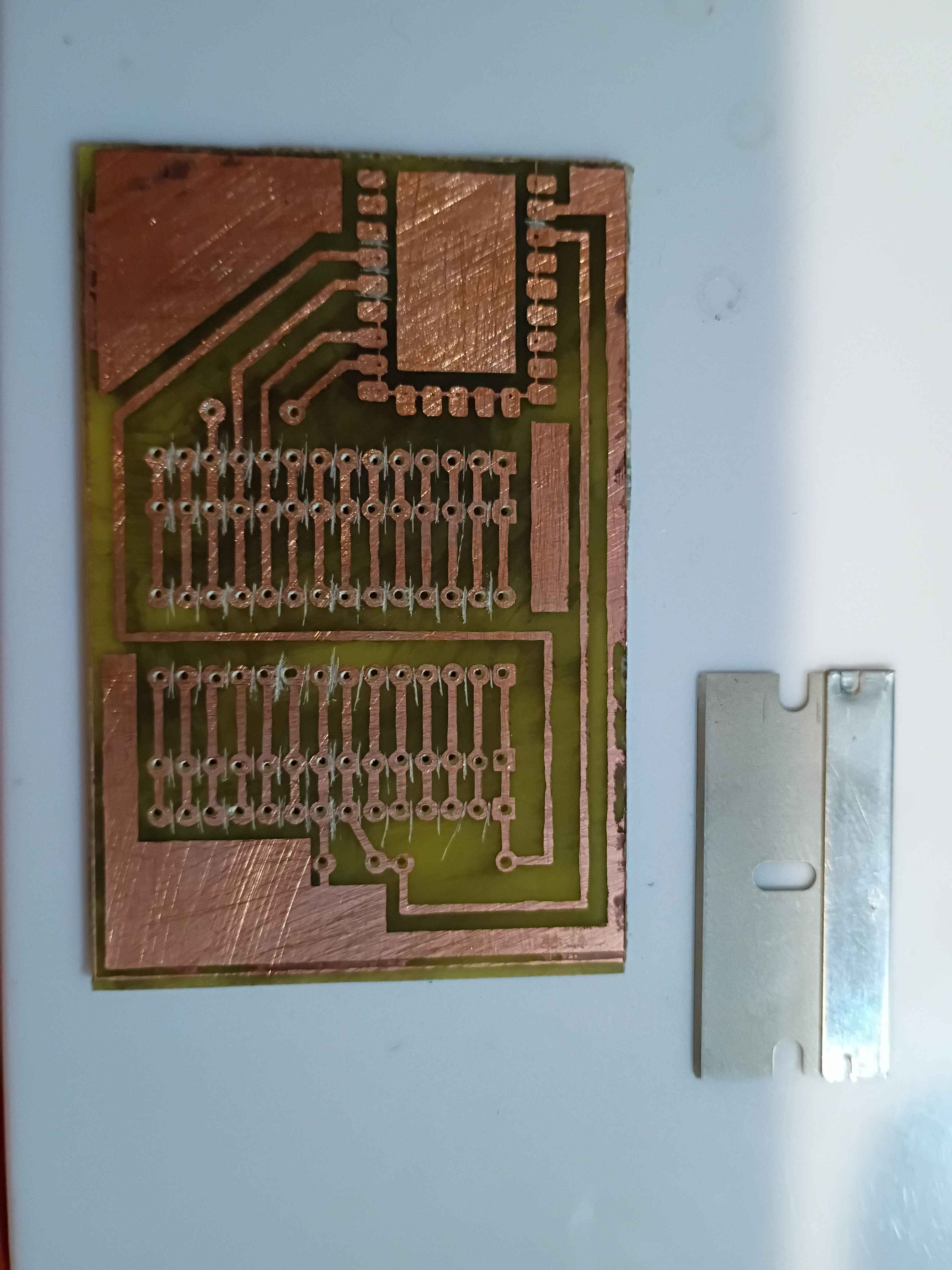
I redid the toner transfer of the B.Cu mask. For the areas that didn't transfer properly, I put some blue masking tape, 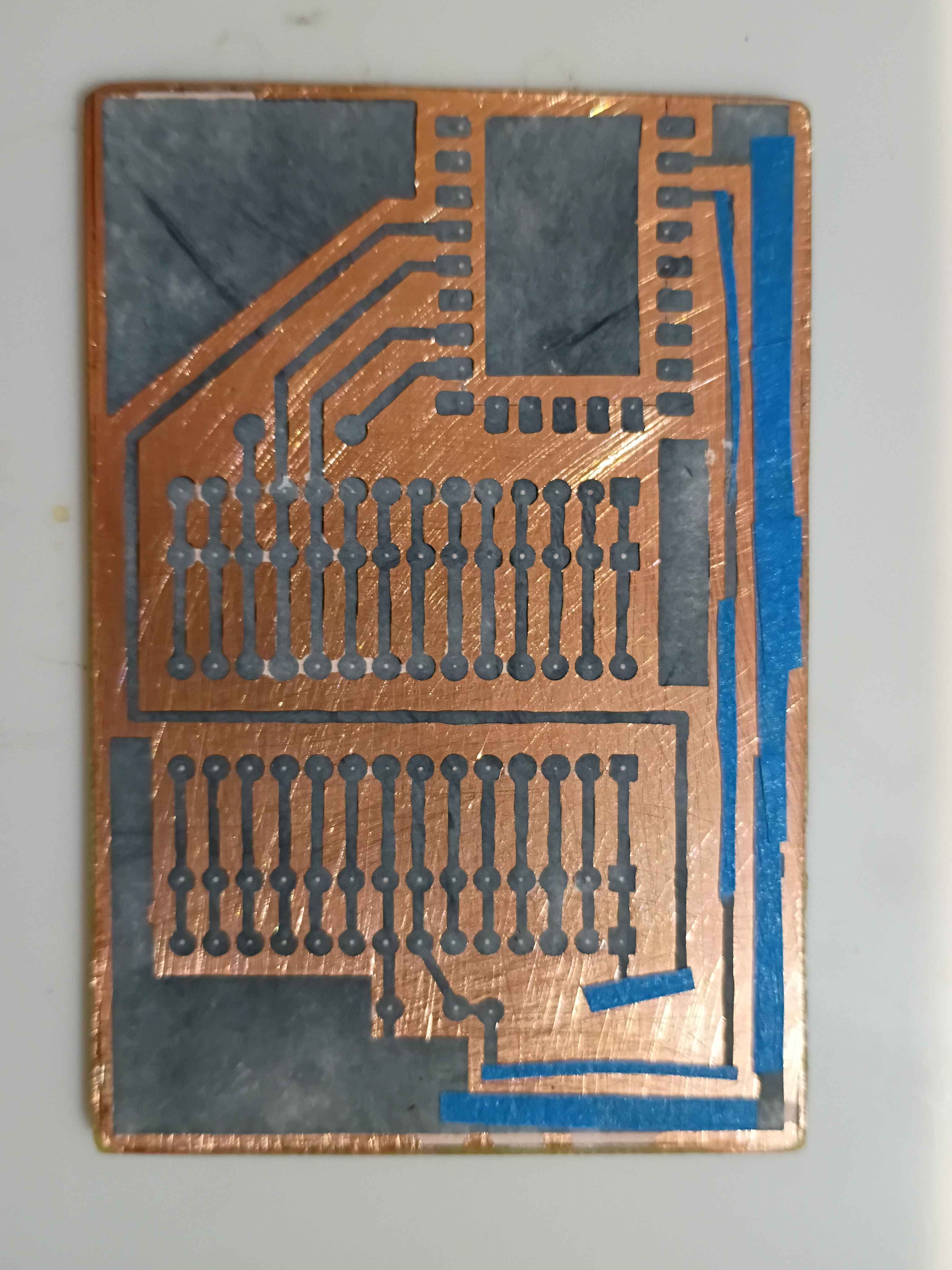
and that worked surprisingly well. I drilled out all the holes and even cut away the rectangle for the RP2040-Zero board. 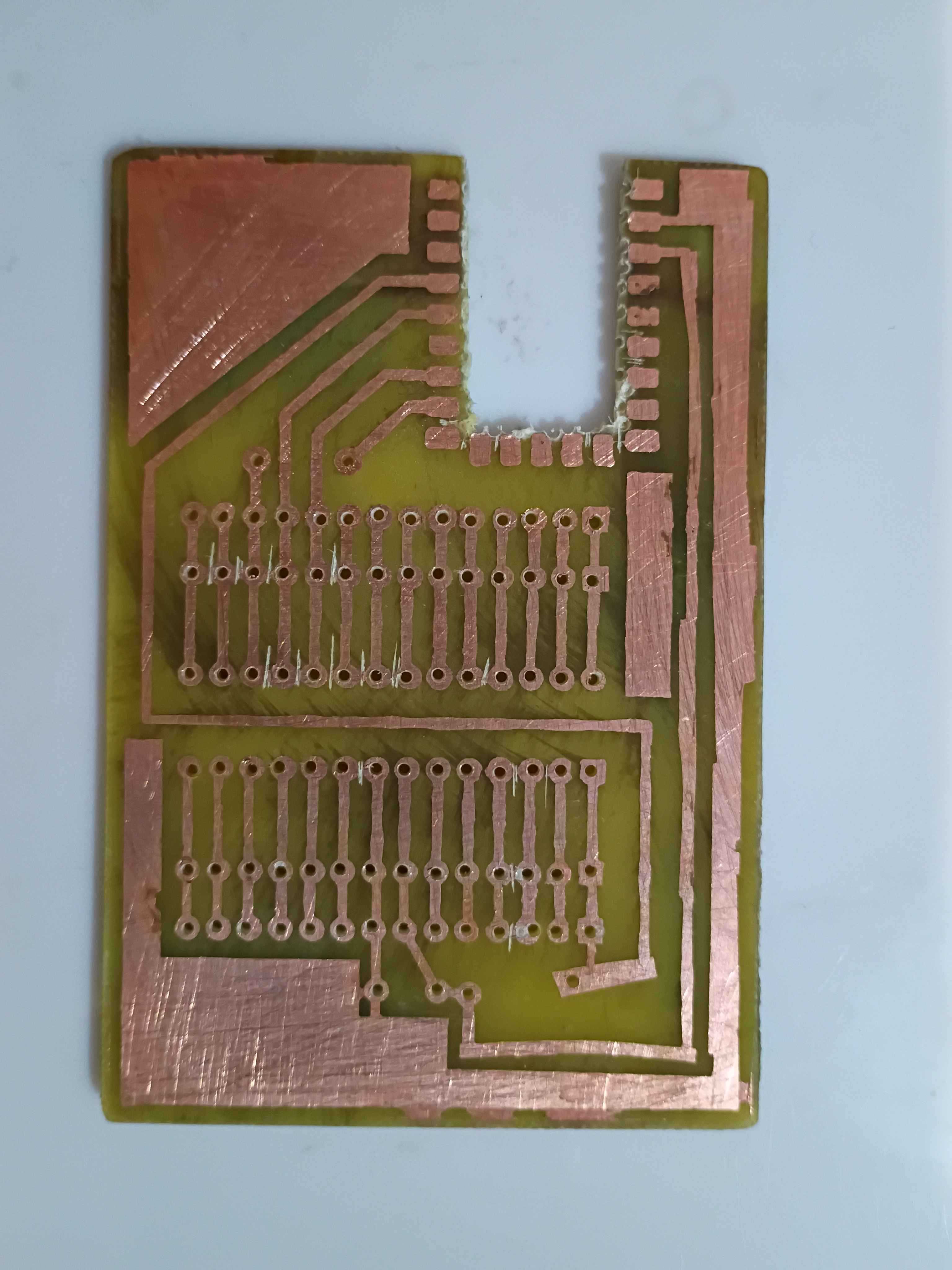
The toner transfer for the F.Silkscreen was not so successful even after a couple of attempts. I think it's because I sanded the fiberglass. I just retraced the parts that didn't transfer with black marker. 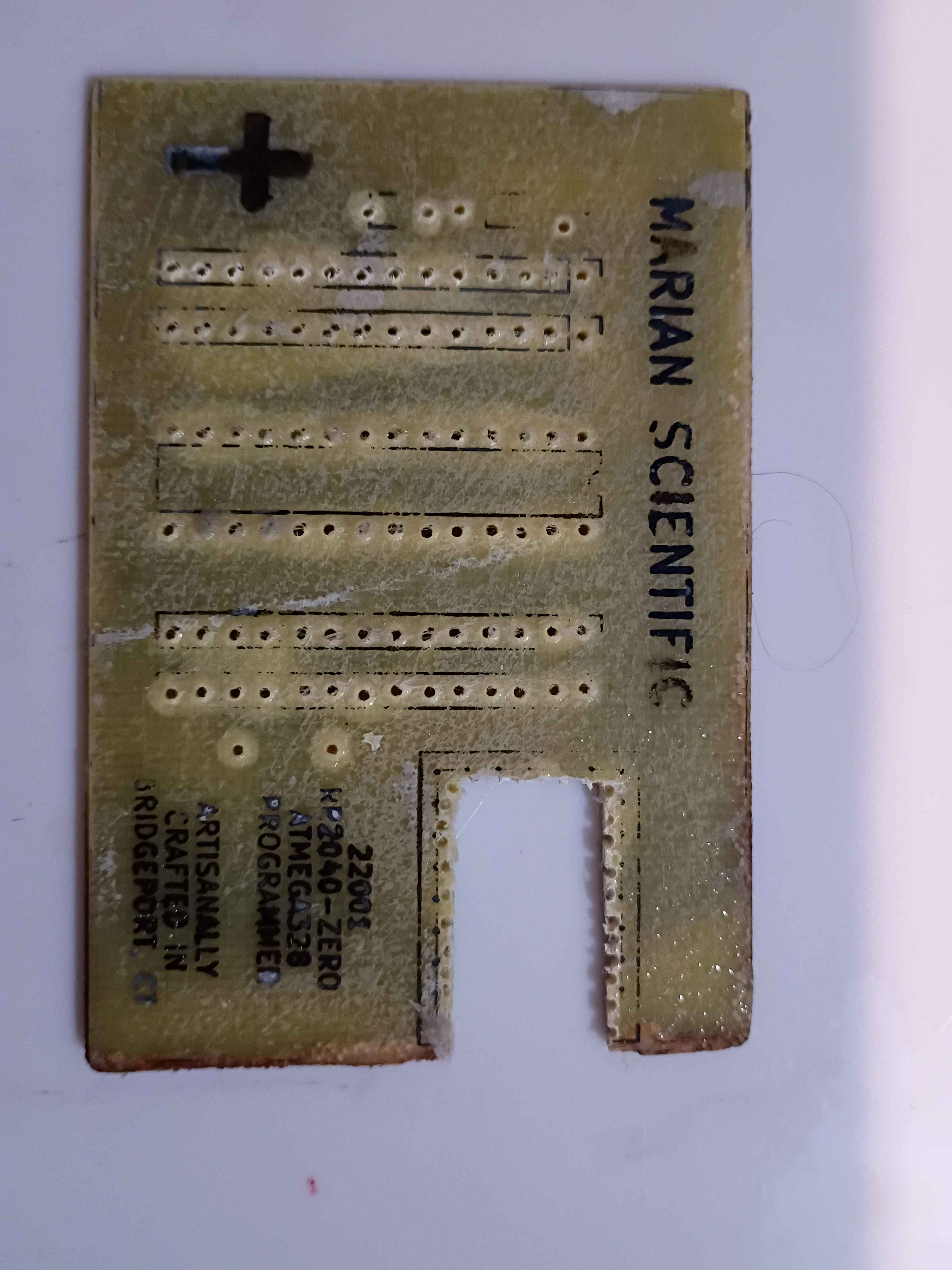
I soldered the components to the board, and it all looks great, until you realize I soldered the RP2040 board inside-out... I need to fix that tomorrow. 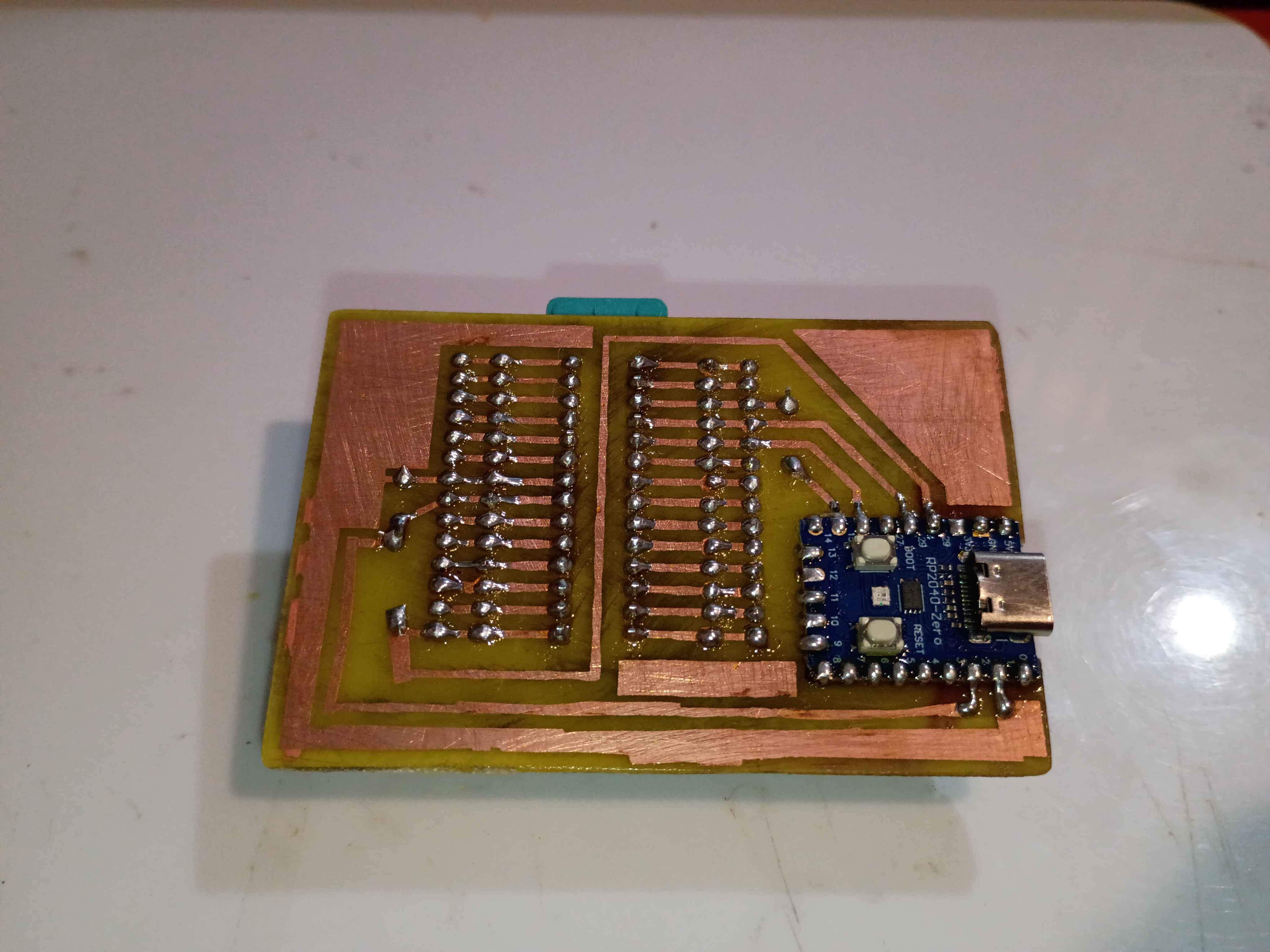
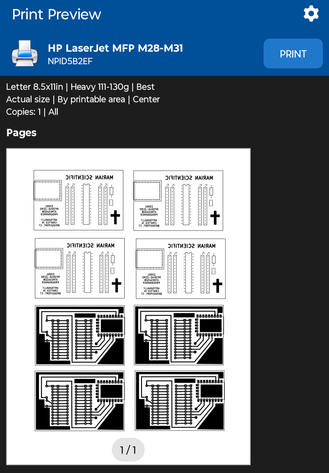
Sigh, apparently printing the PCB mask PDFs from my phone was a bad idea, since it automatically resized them down a few percent to "Fit to Page", and now none of the components fit, rendering a few hours of work yesterday and today completely wasted, except of course the practice etching and the lesson learned.
I reprinted the PDF with "Actual Size" scaling using the NokoPrint app and the settings below.
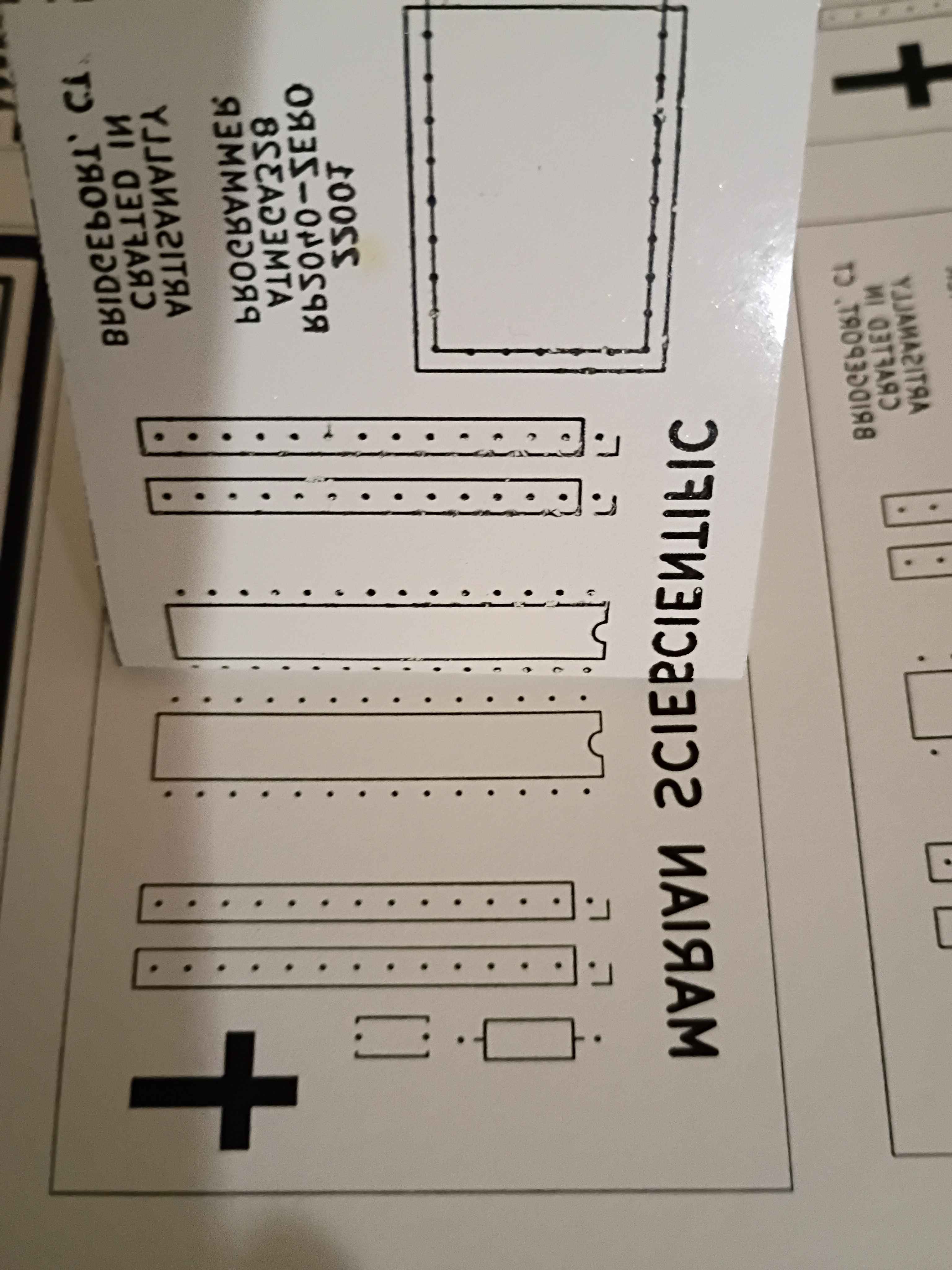
Before I realized I had the sizing wrong, I did retry the toner transfer of the front silkscreen, and it mostly worked, although the cross and some of the letters did not come thru. The areas of toner that didn't transfer properly, I filled in with marker. I can try again with the correct sizing tomorrow, which should help, although the cross probably didn't have enough direct heat applied to it to transfer.
Used Inkscape to put a bunch of the background copper and silkscreen masks onto a single sheet and printed that on glossy paper. 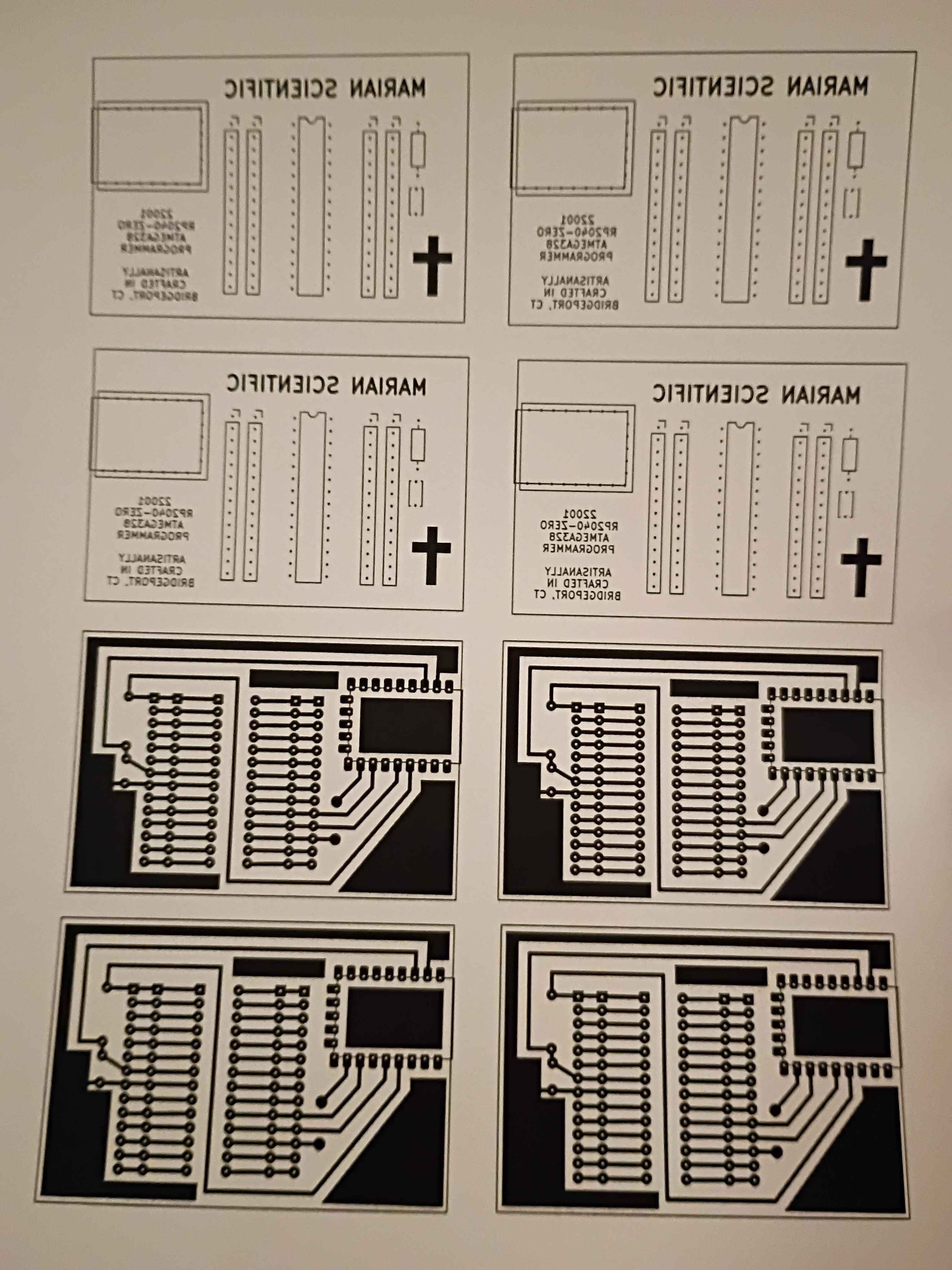
Hopefully successfully implemented a minimum set of functions for Mary-Bot. This post is the first test of the live software.