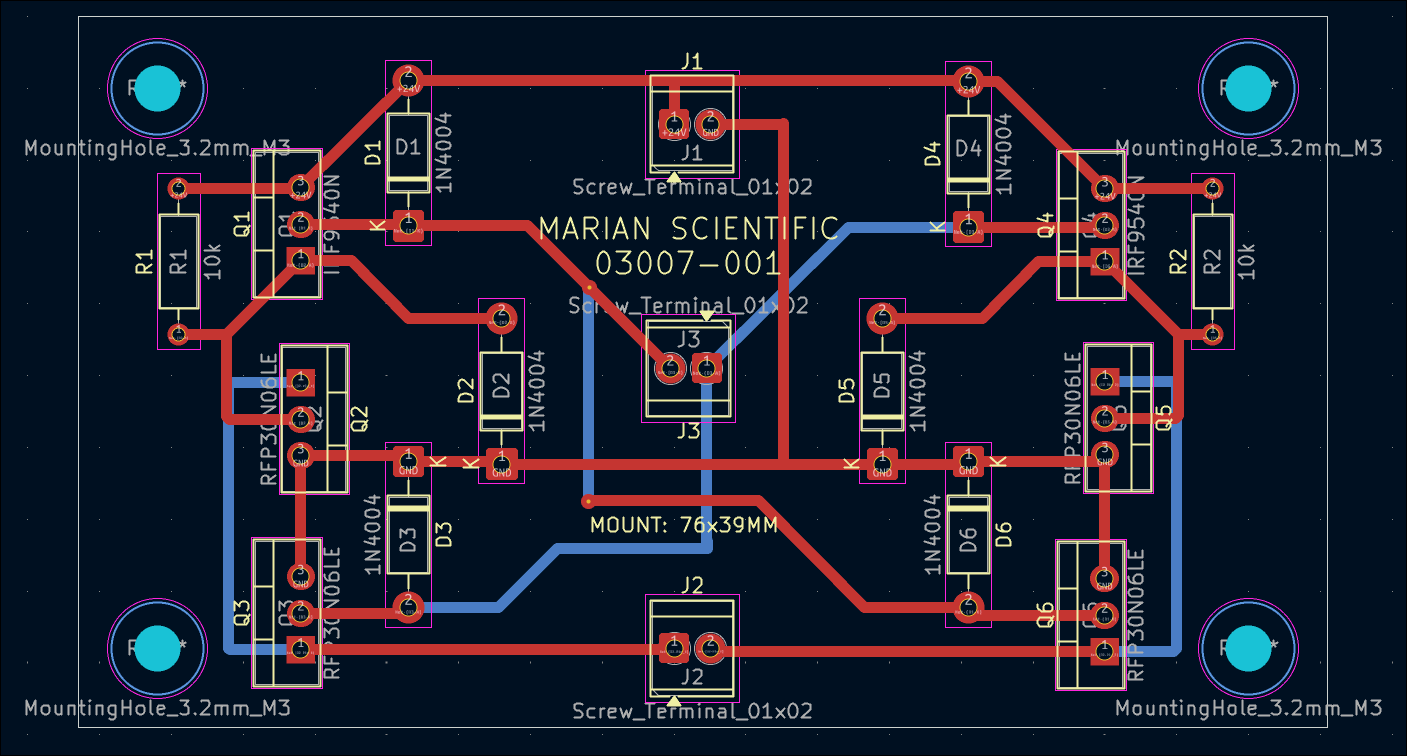
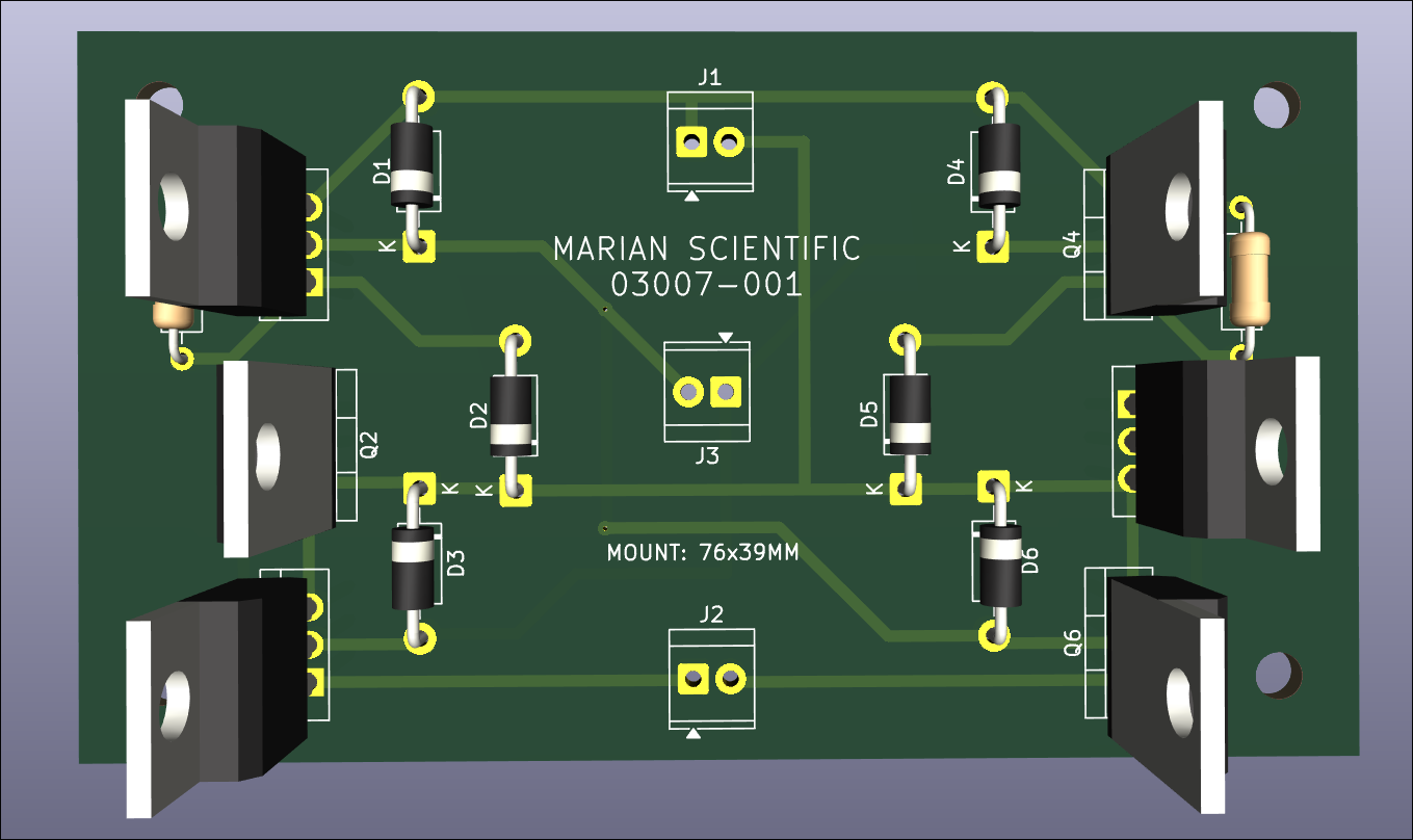
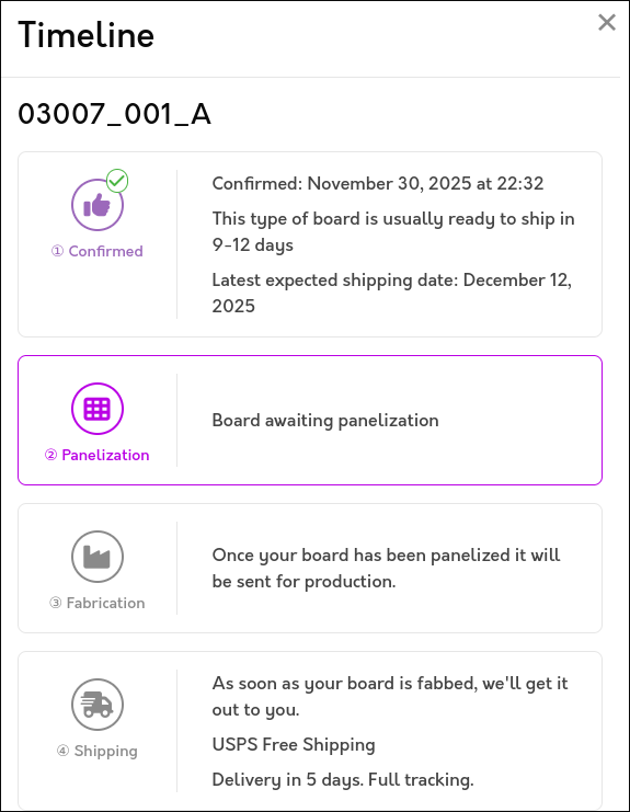
Designed and ordered 6x stepper motor driver PCBs from OSHPark to compare against DKRed. See CAD files. Submission was seamless, and they give better visibility into the order timeline. Pricing is comparable to DKRed. I decided not to expedite.
I updated the web journal-generating script to categorize entries by submission month and reorganize the main page by project/author and the most-recent 10 entries. This is to improve page load times. A similar monthwise breakout eventually needs to be done at the author-level as well.
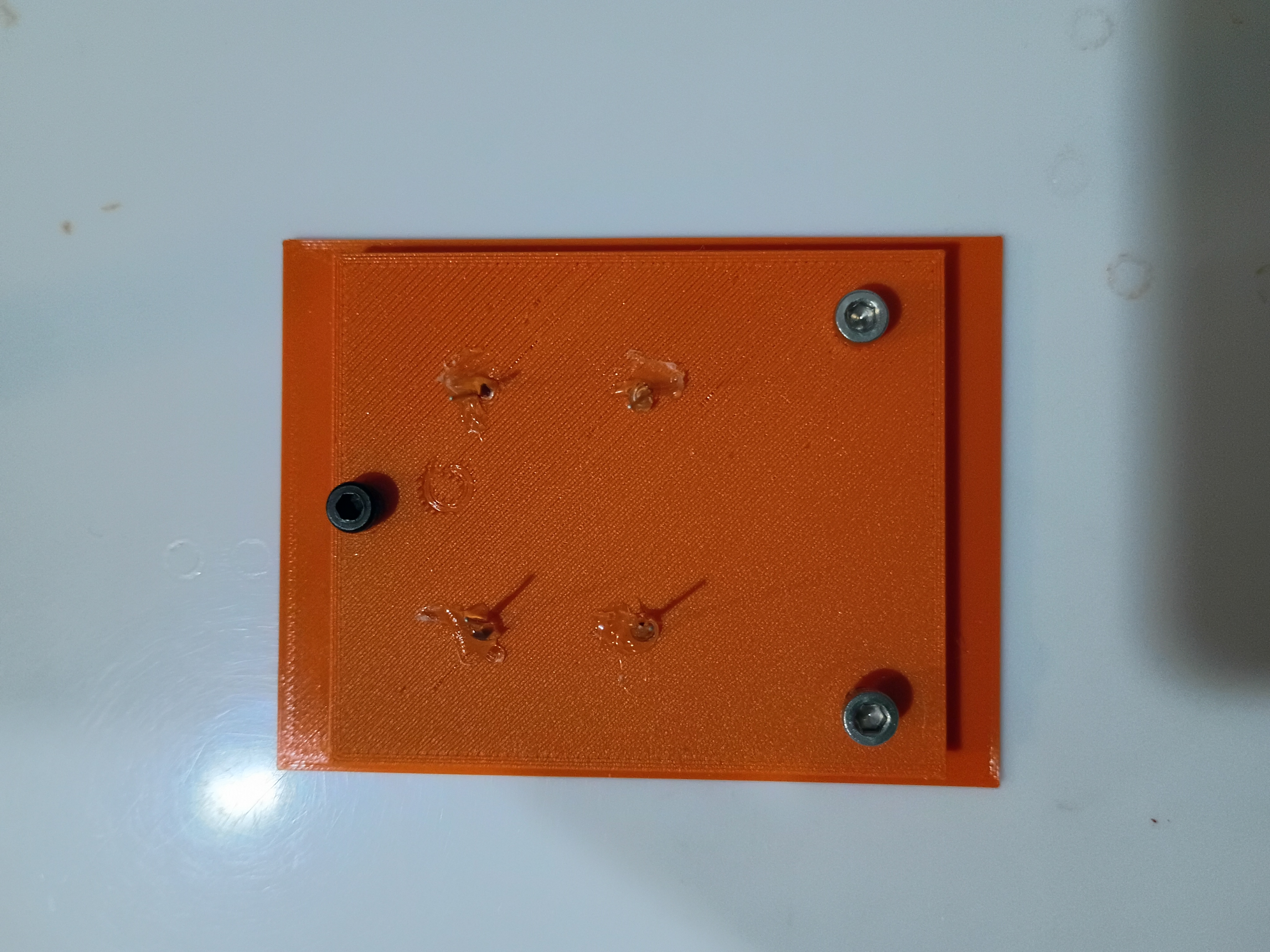
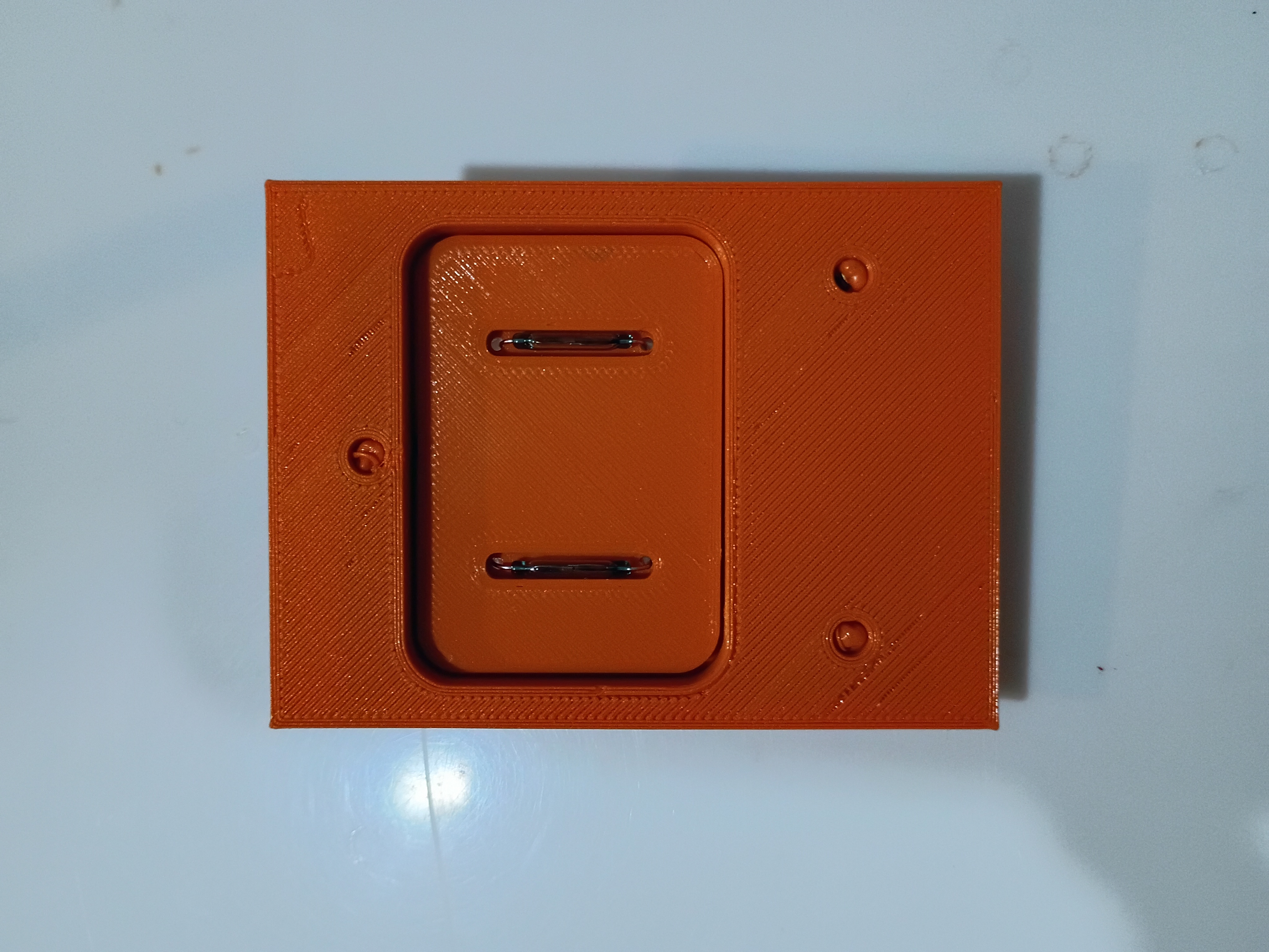
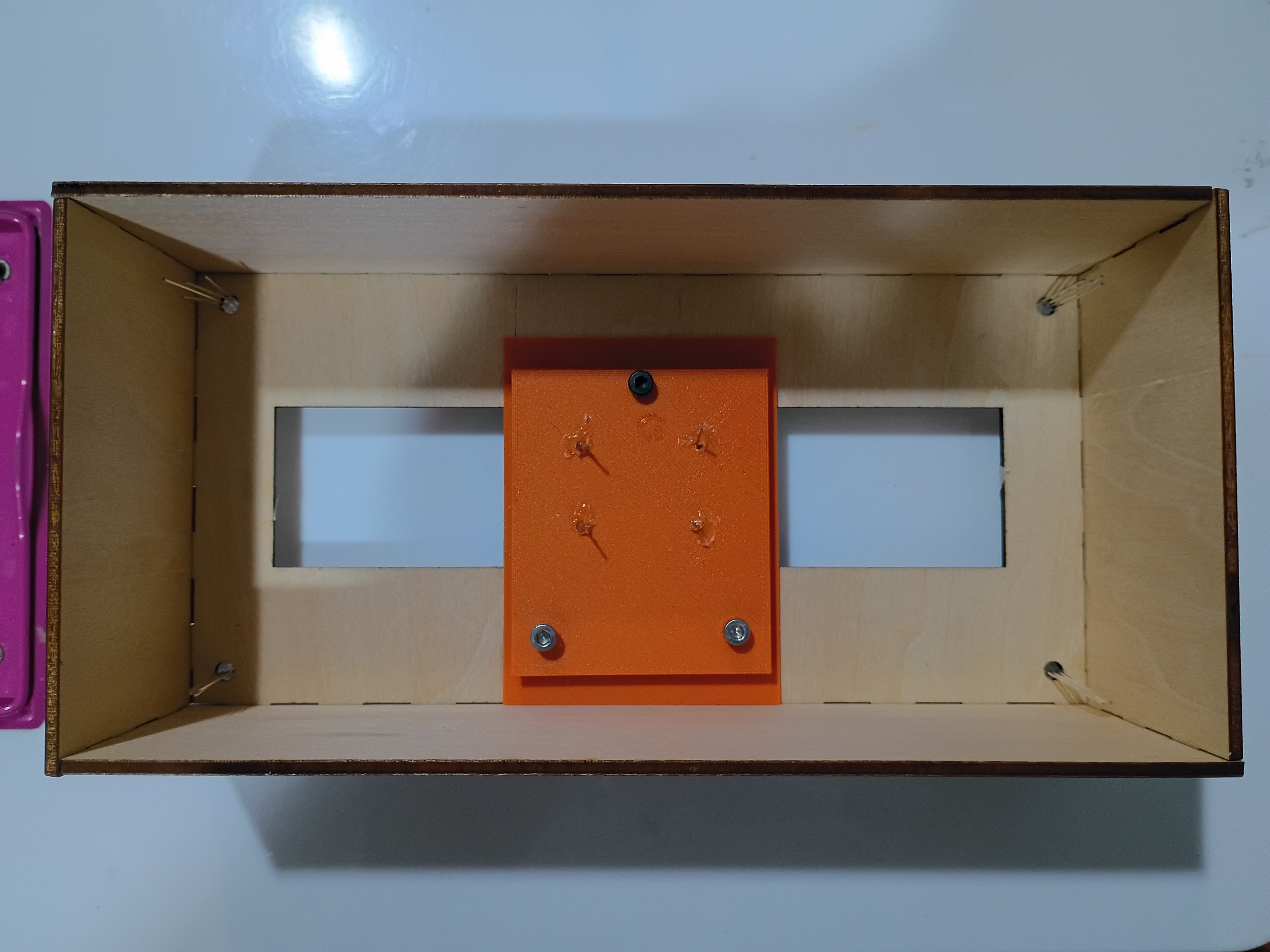
Reprinted magnet block with 2 holes to accept 2 magnets which must be oriented with opposite polarity facing out for best detection by the reed switches. See example. Also glued mounting blocks for the bottom acrylic plate. 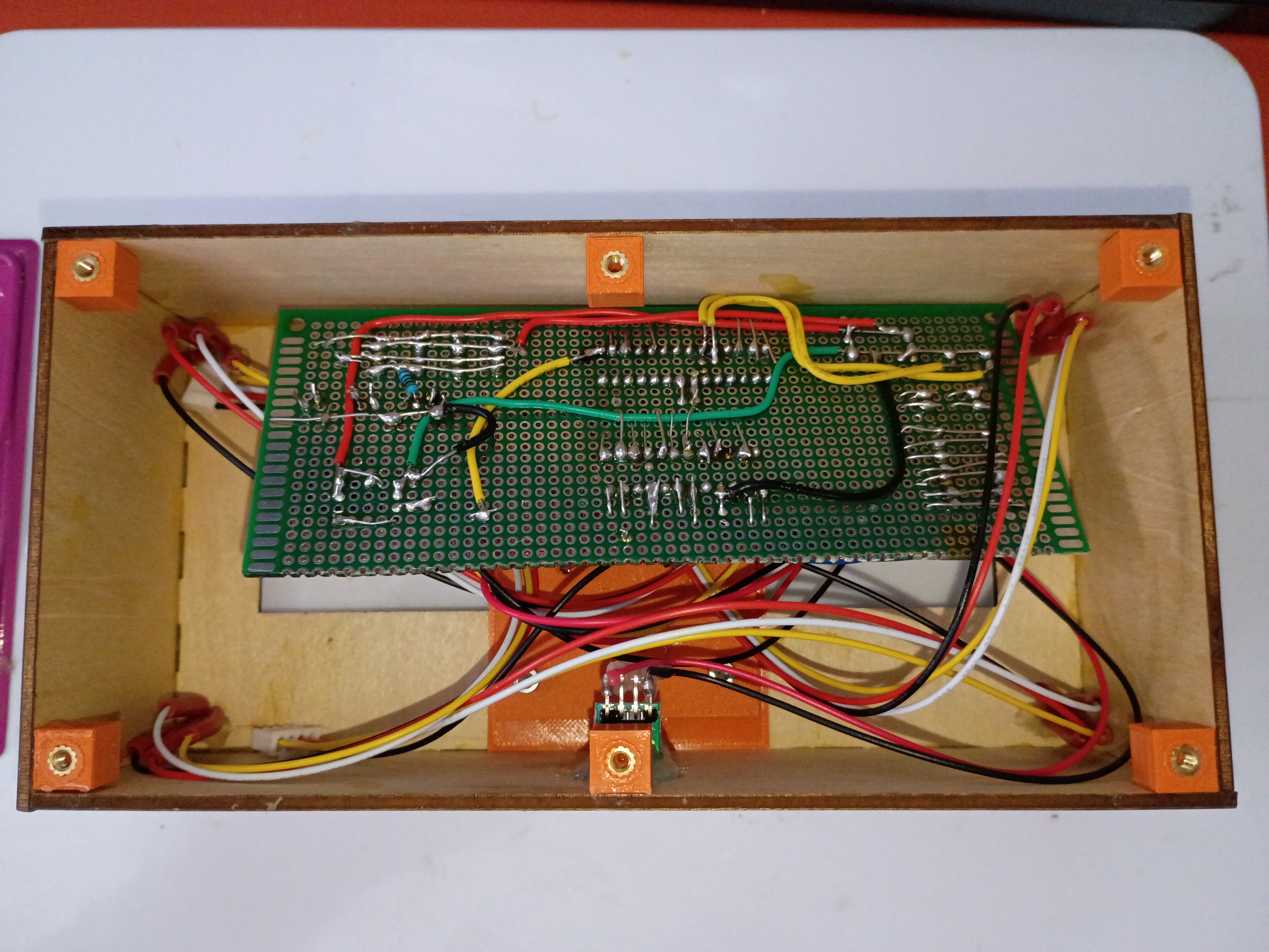
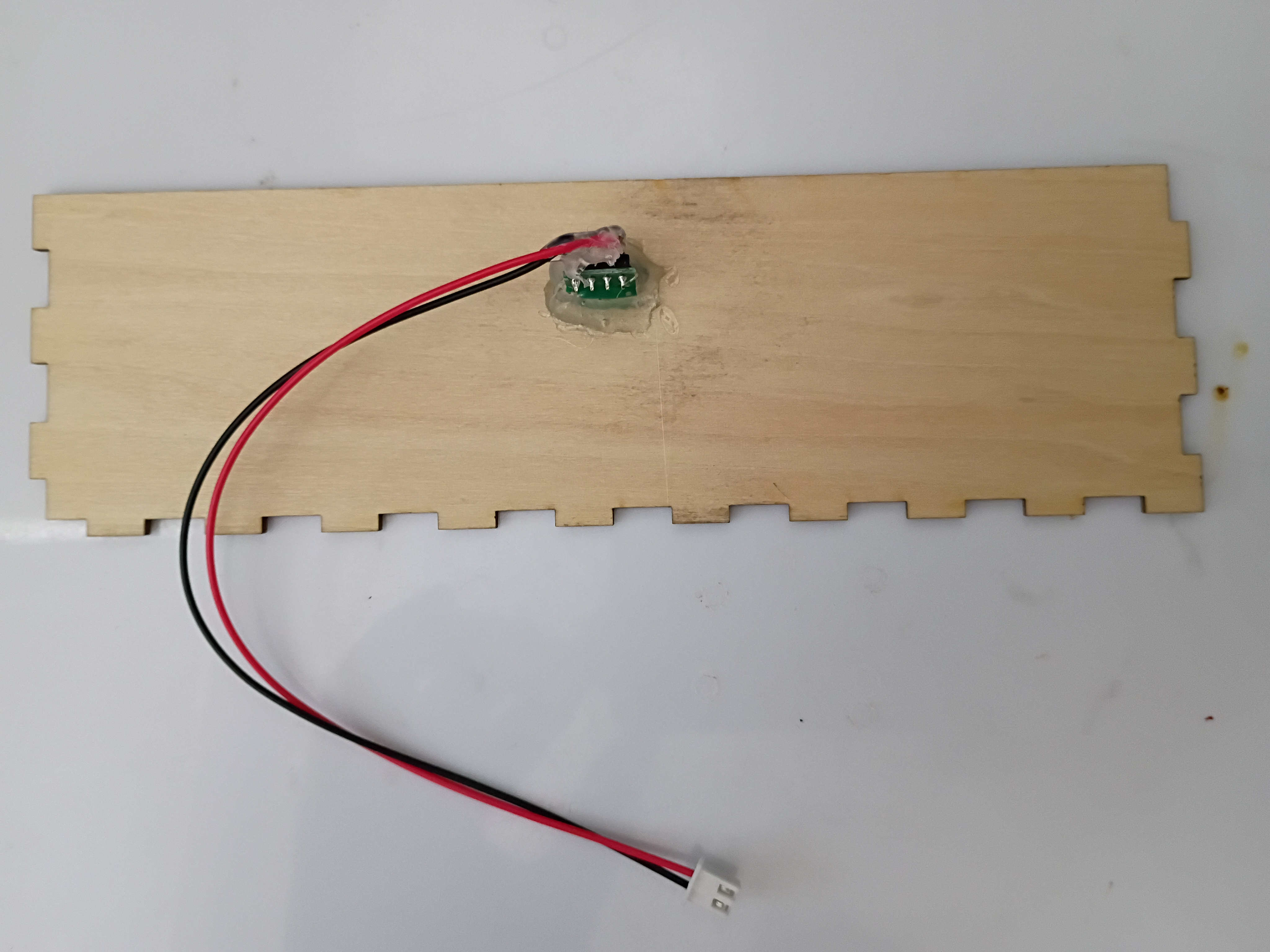
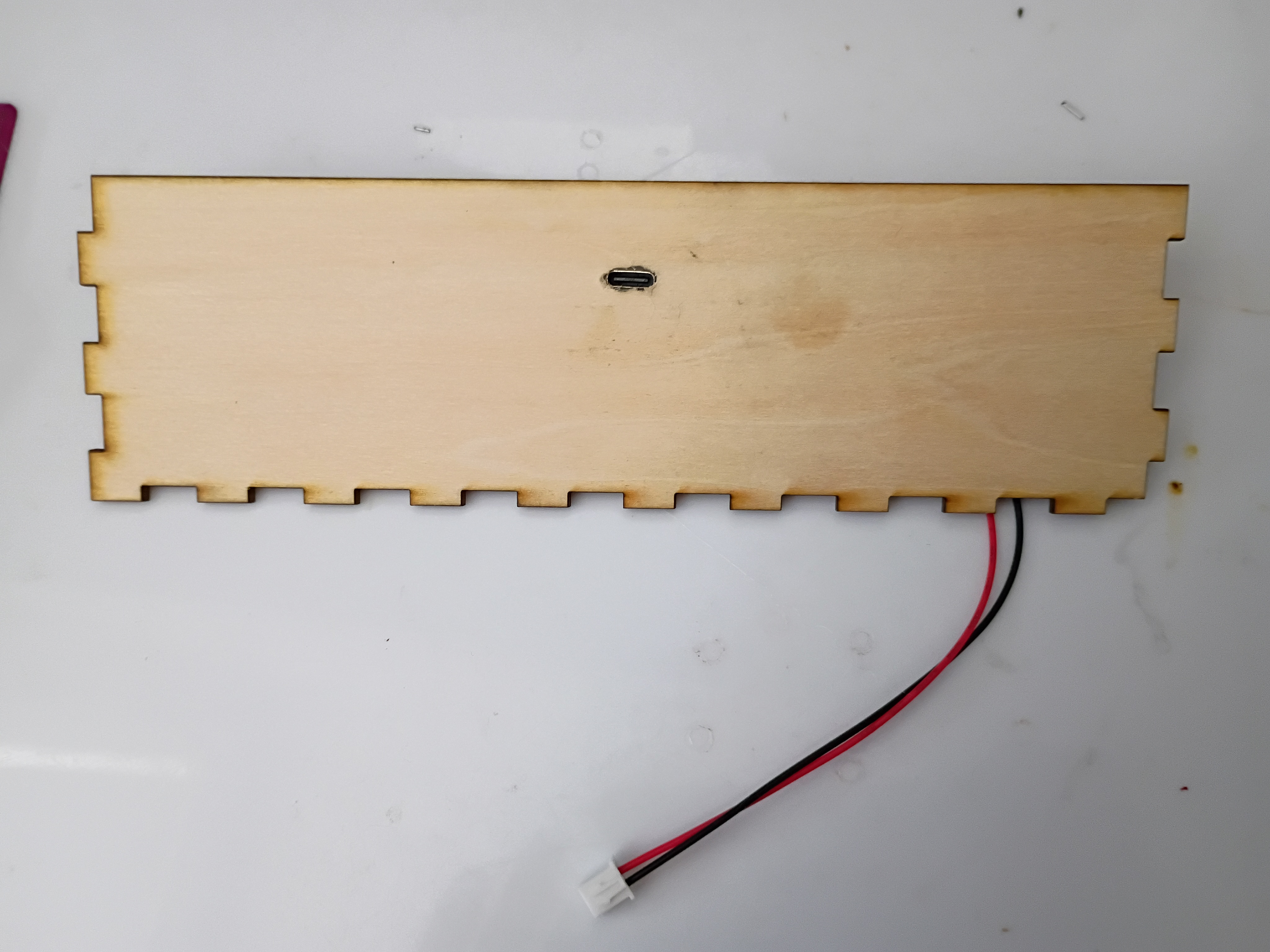
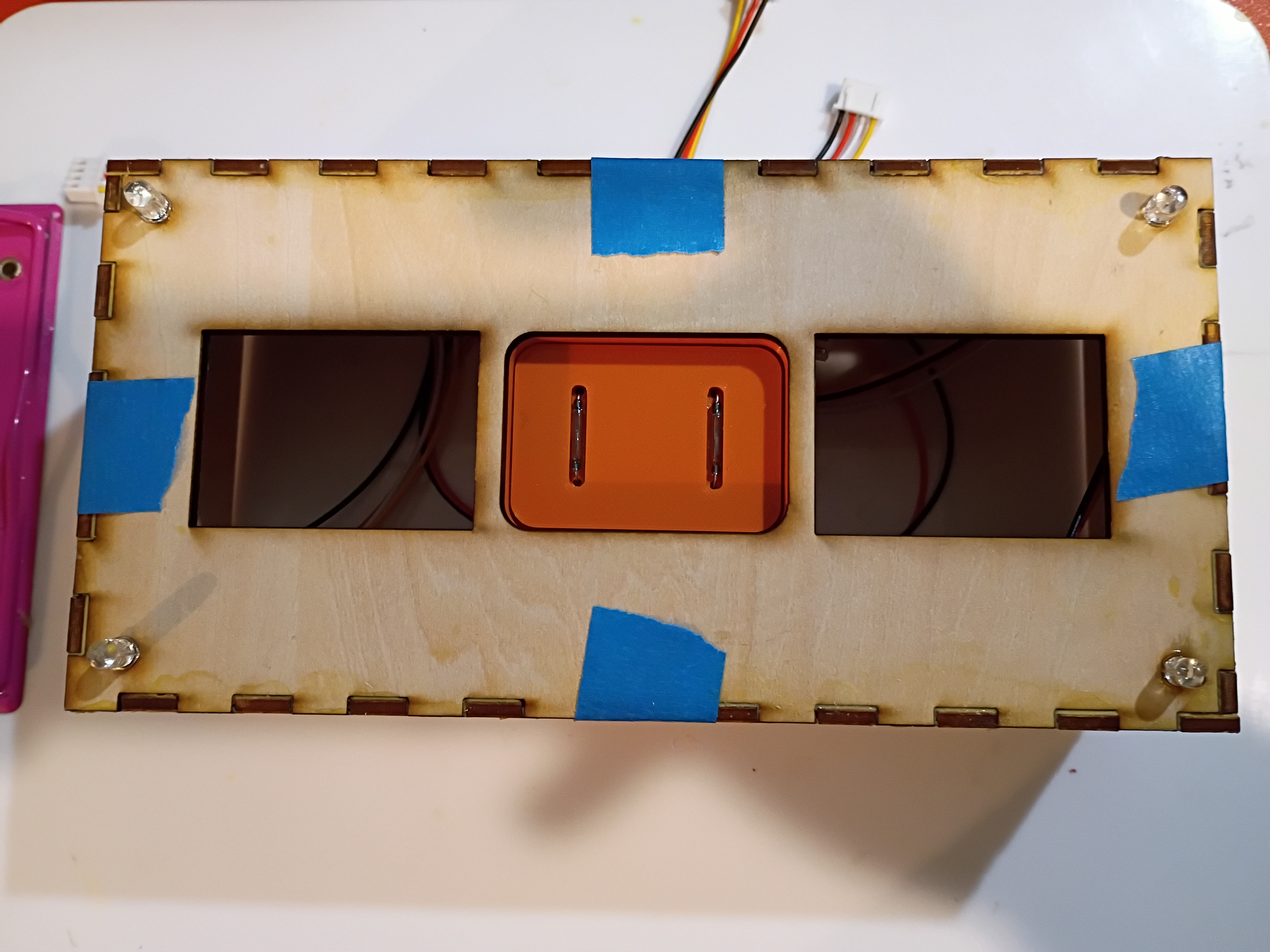
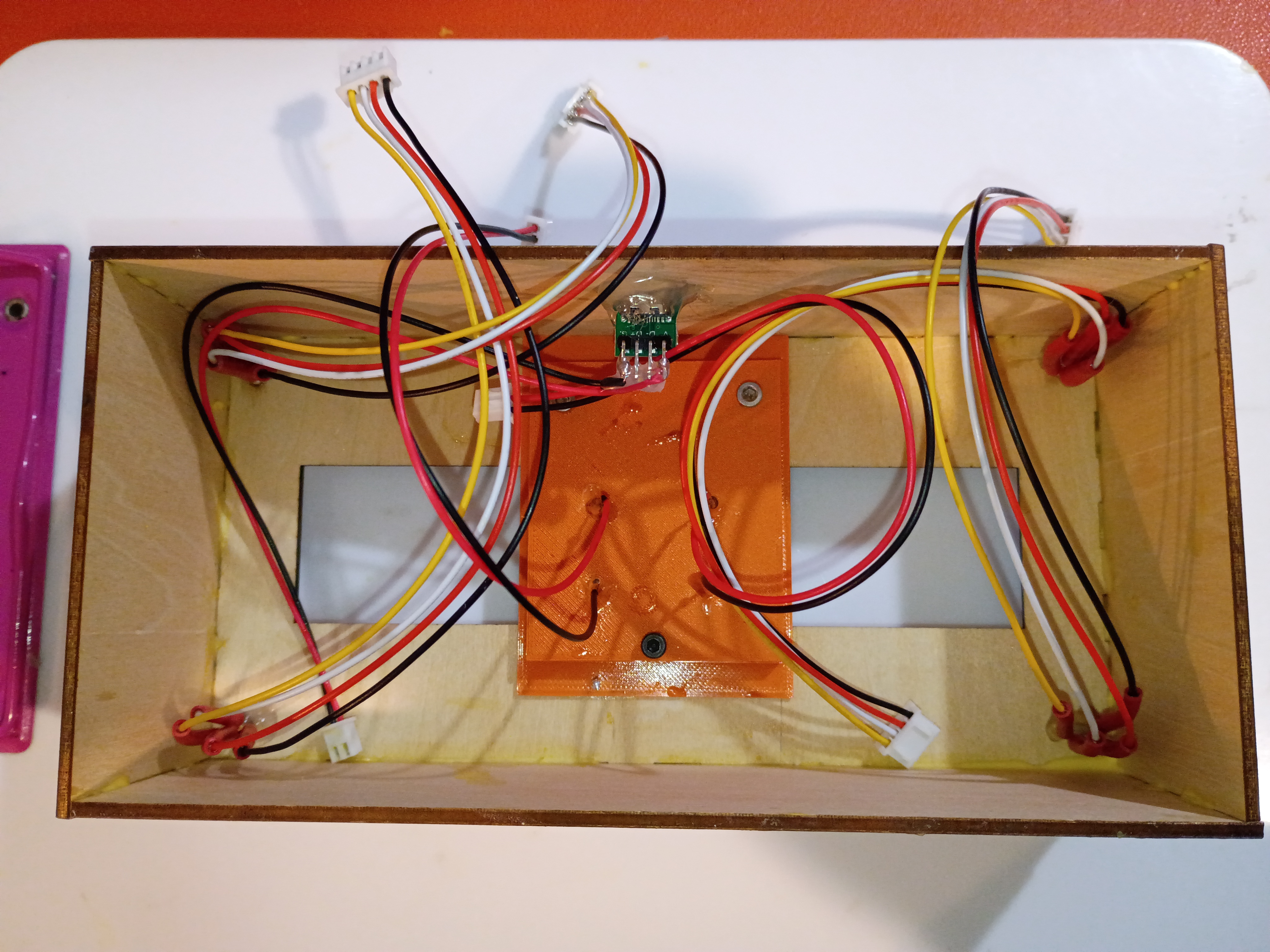
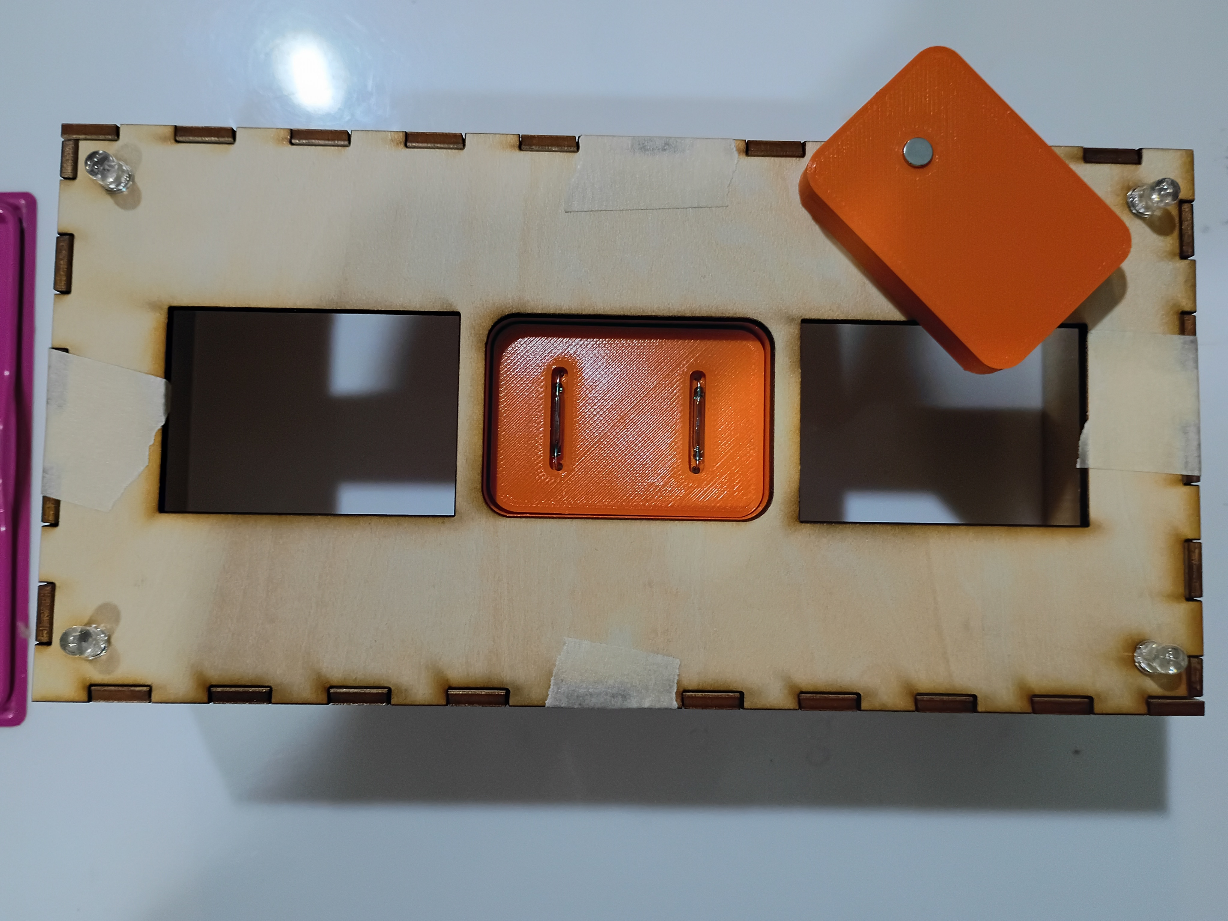
Drilled slot in box and mounted USB-C connector. Mounted, soldered, and heat-shrunk leads to all indicator LEDs and reed switches. Soldered additional JST sockets for the reed switches onto the main circuitboard. Glued box together. Tested magnetic field detection with this C code. 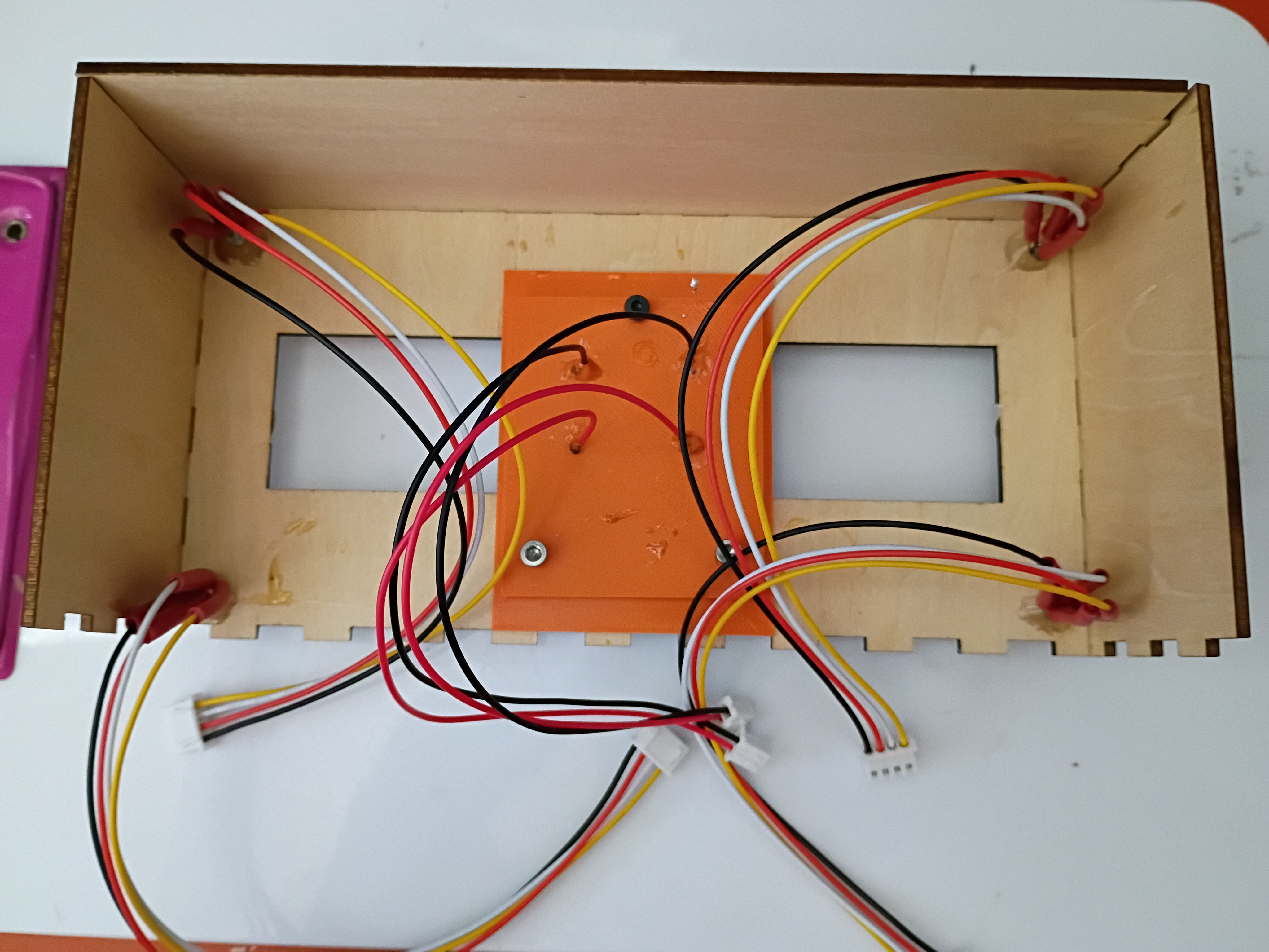
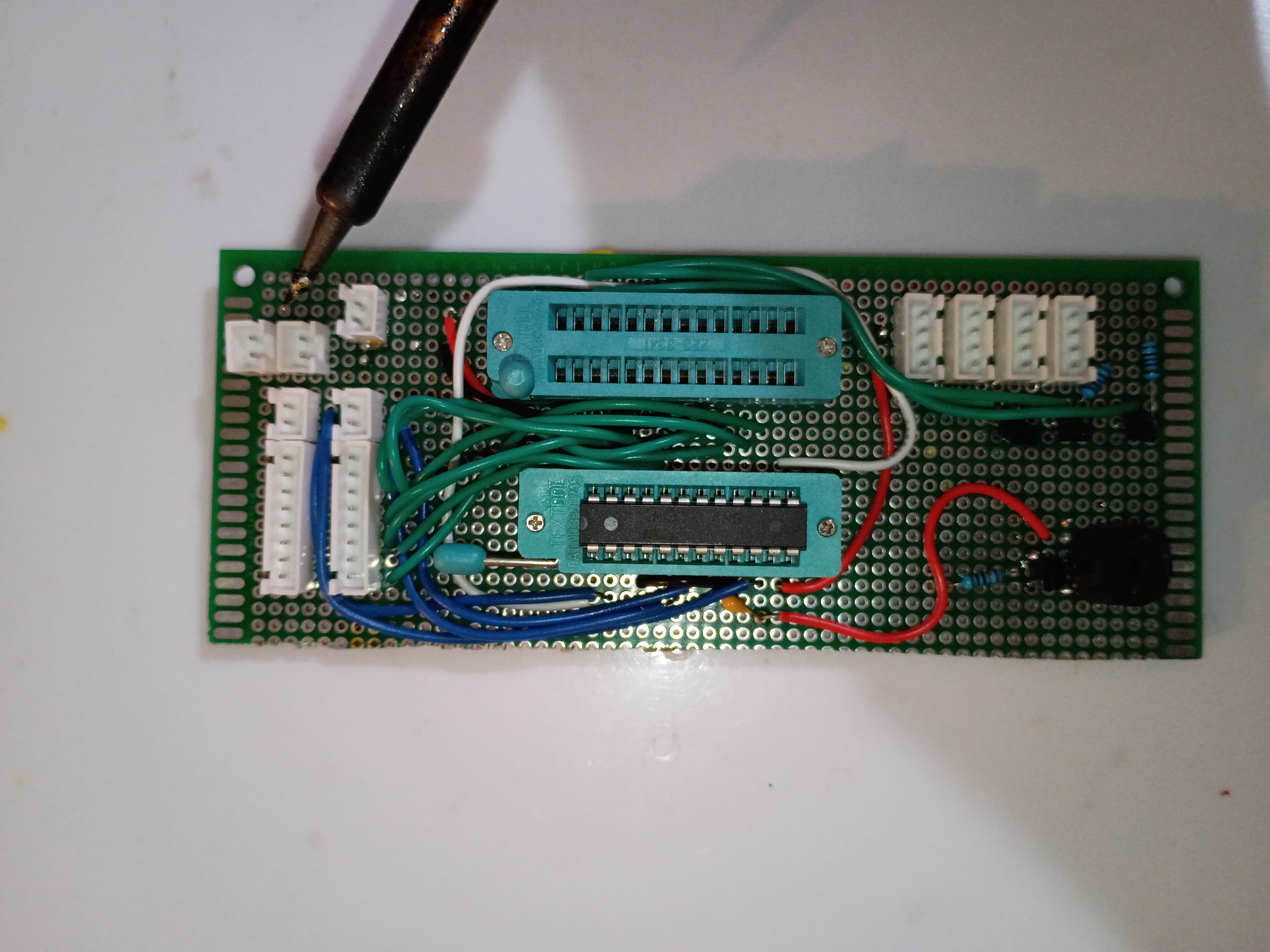
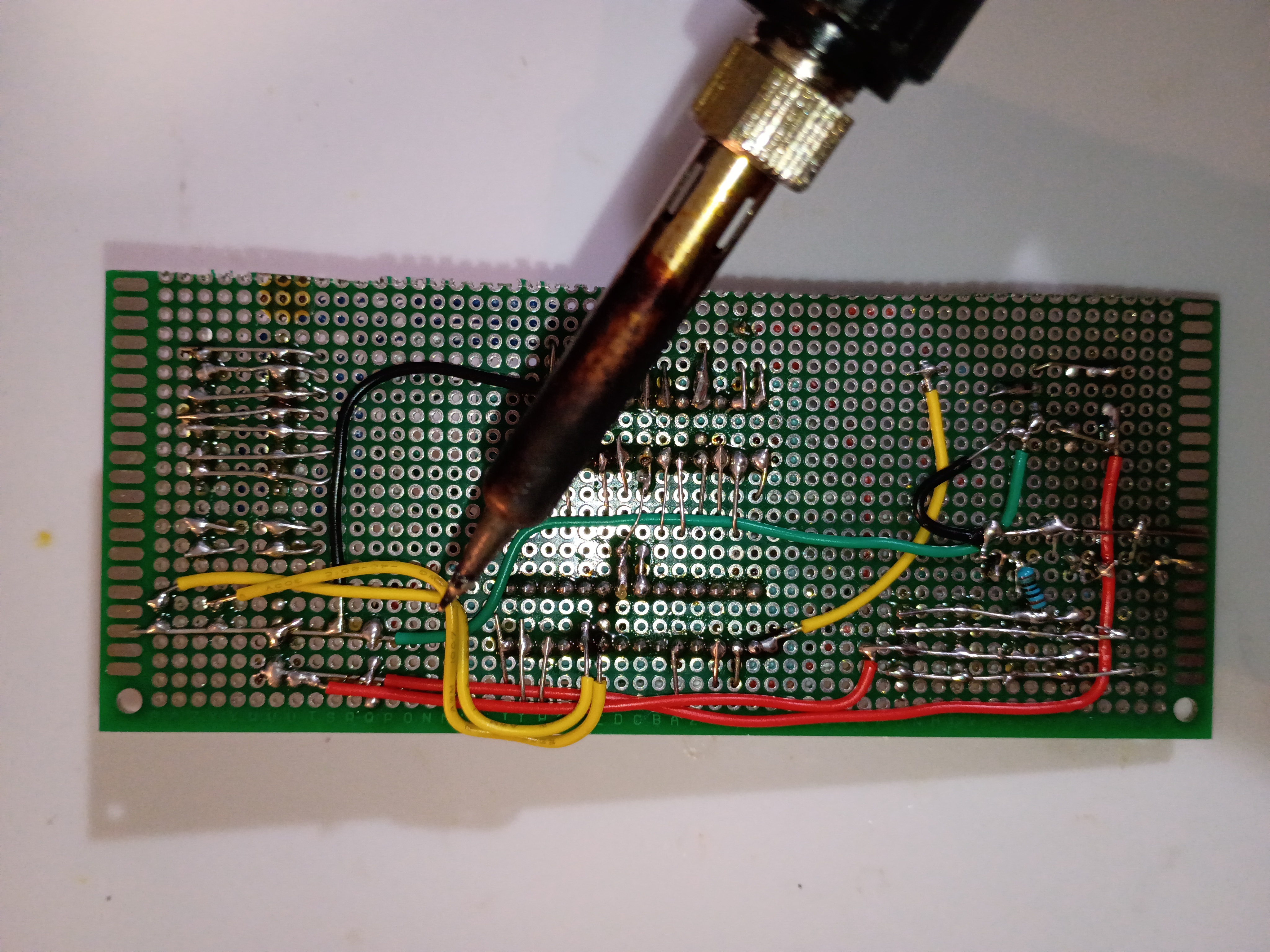
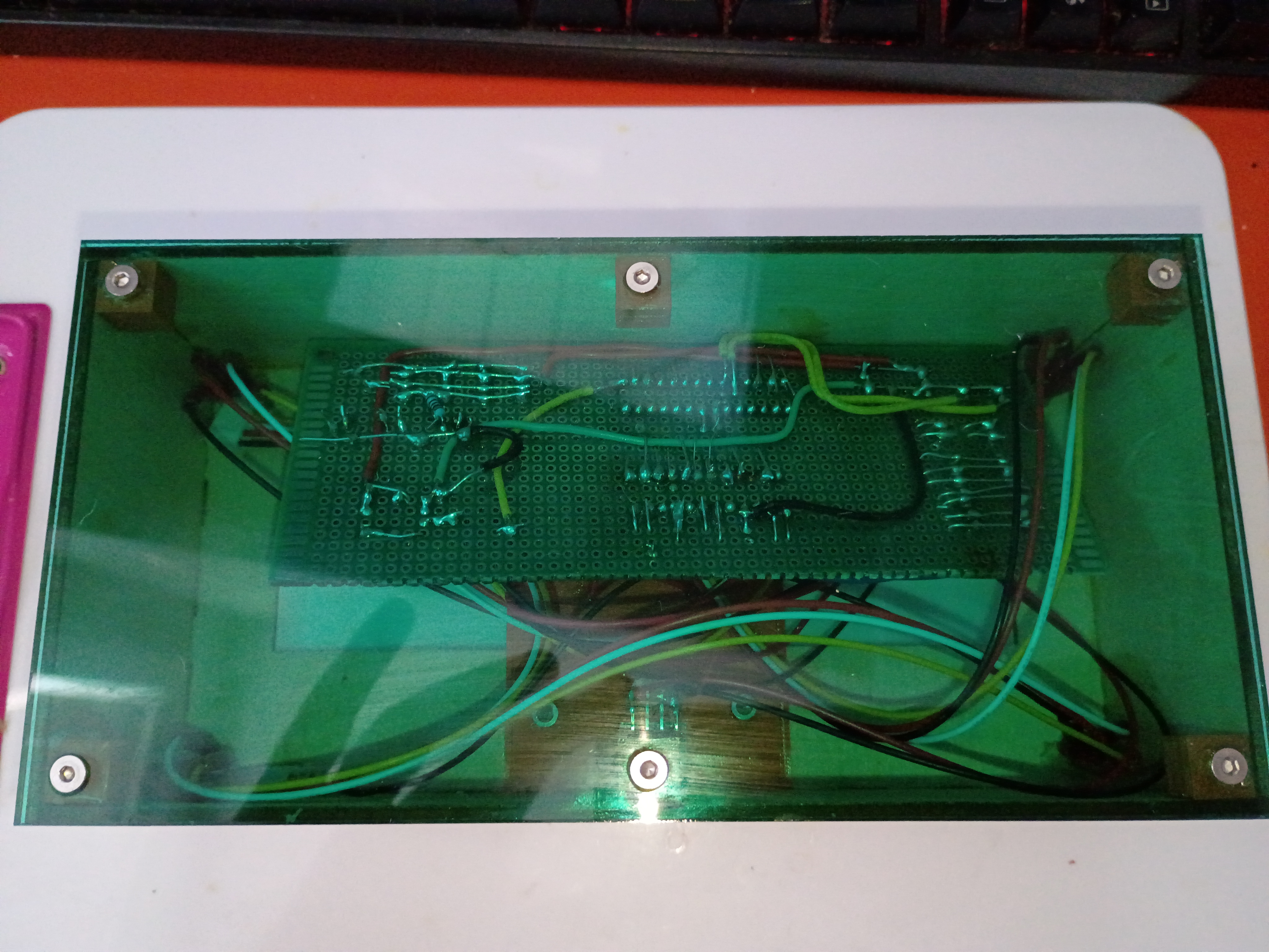
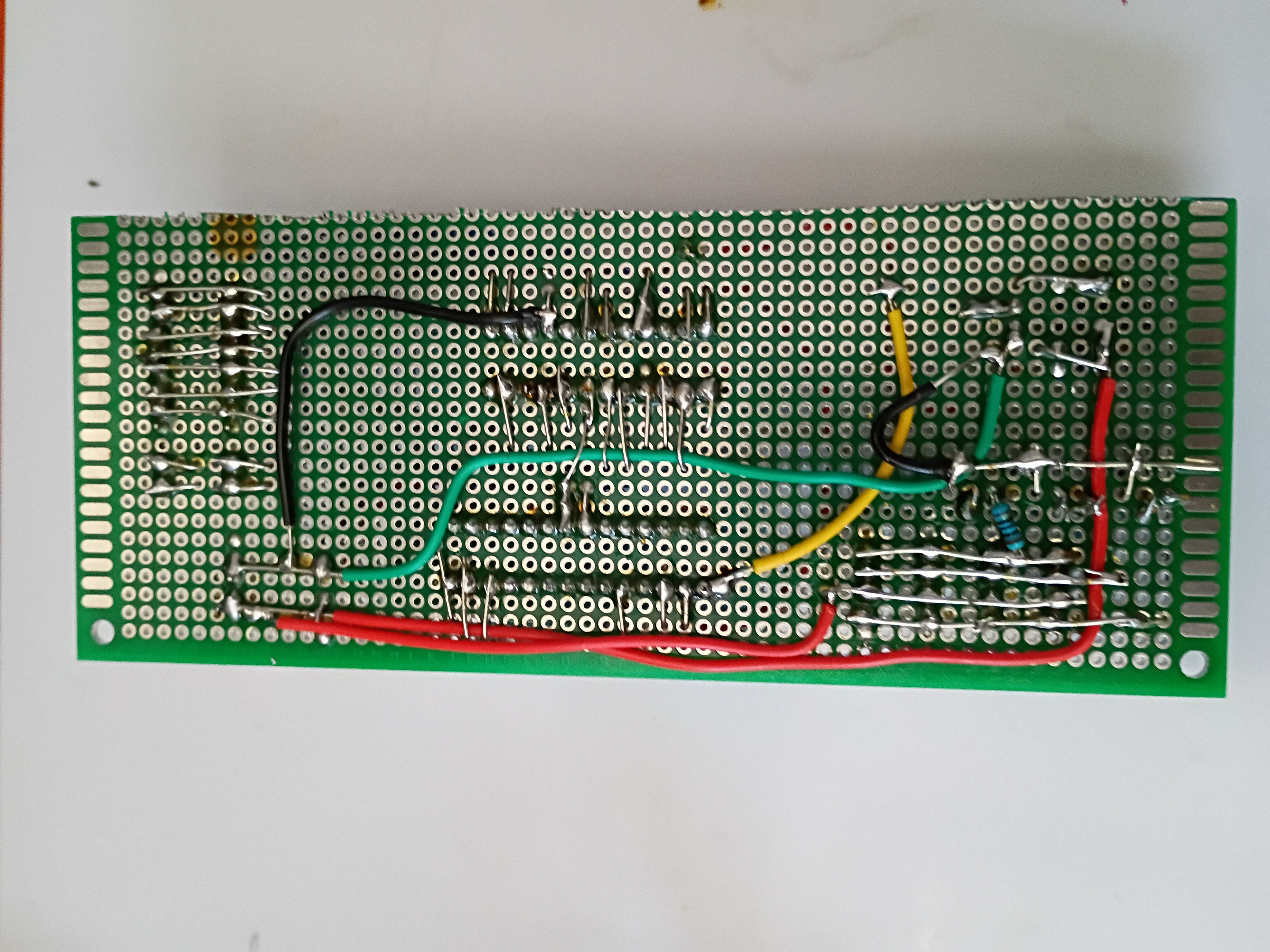
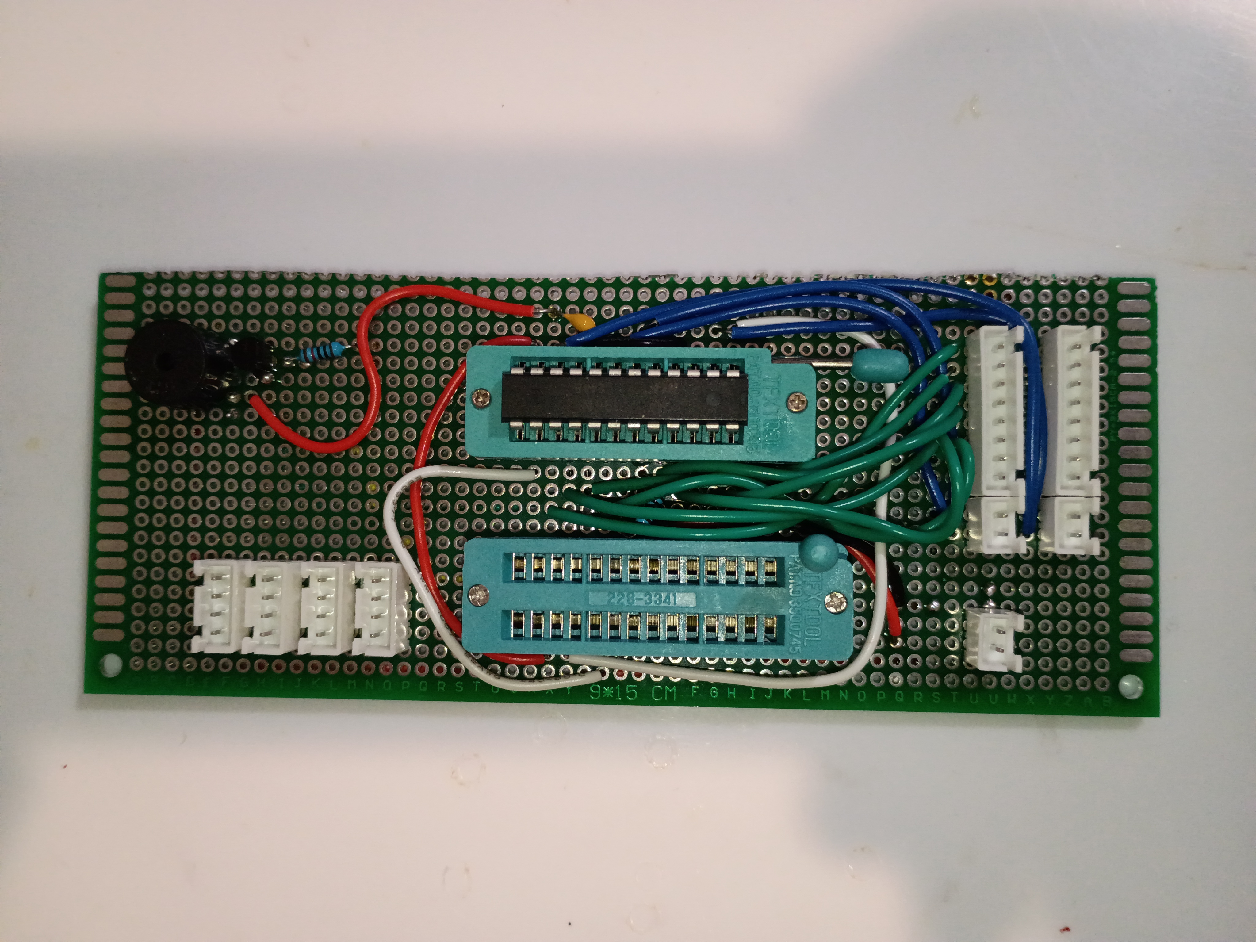
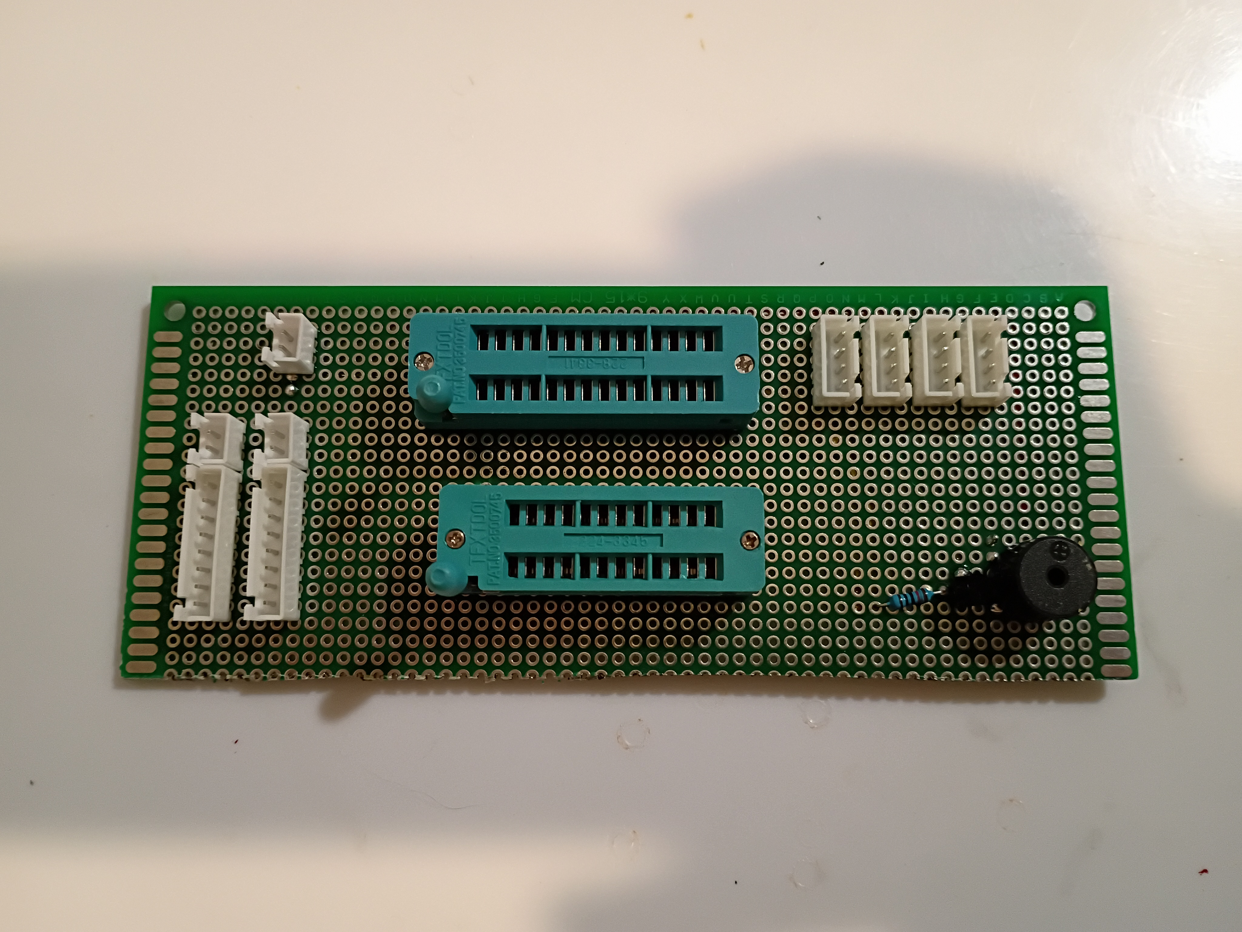
Finished soldering components onto main perfboard. 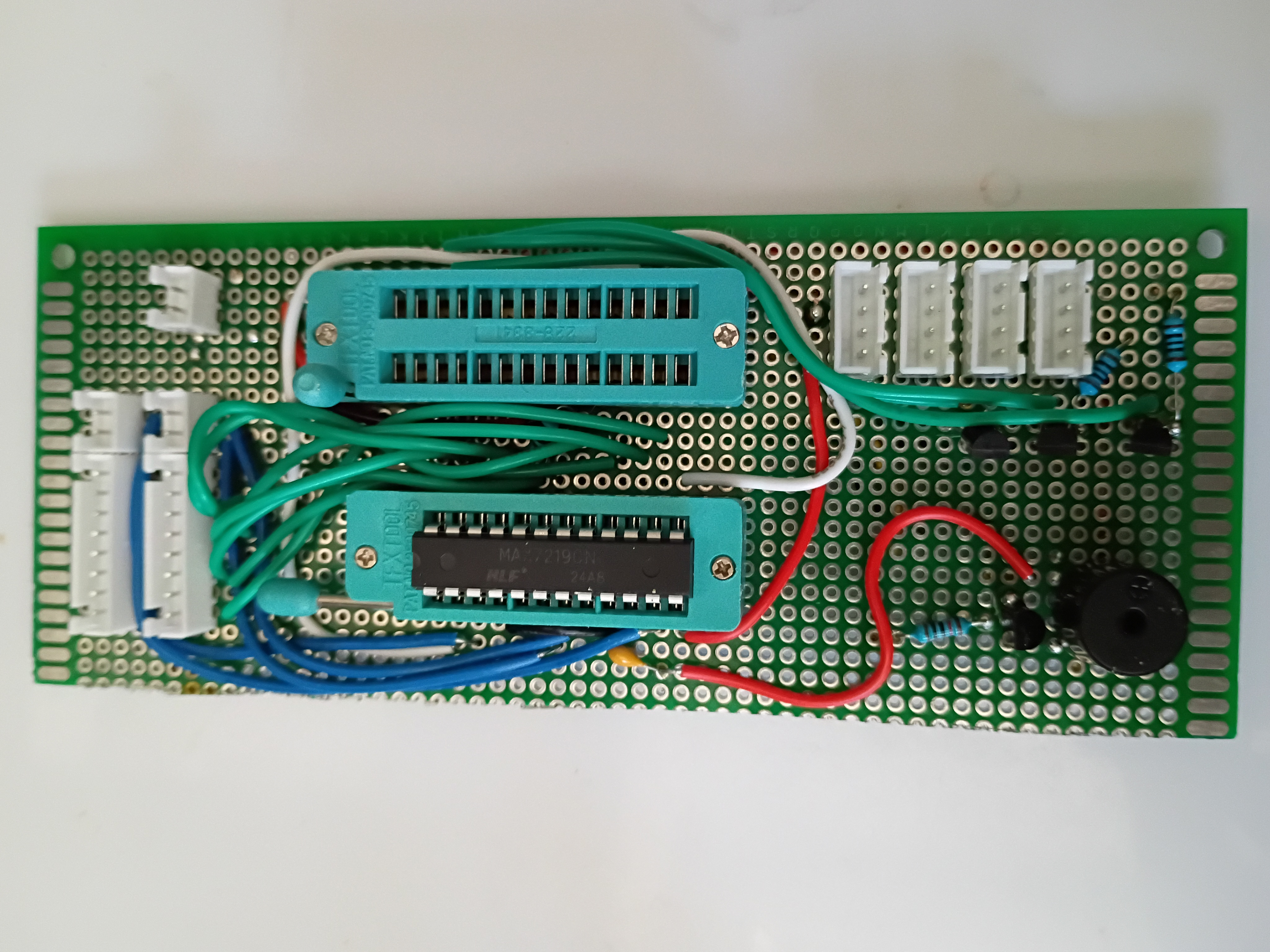
Circuit and code to blink multiple RGB LEDs in unison using 2N7000 mosfets since they draw slightly too much current to be driven by GPIO directly. 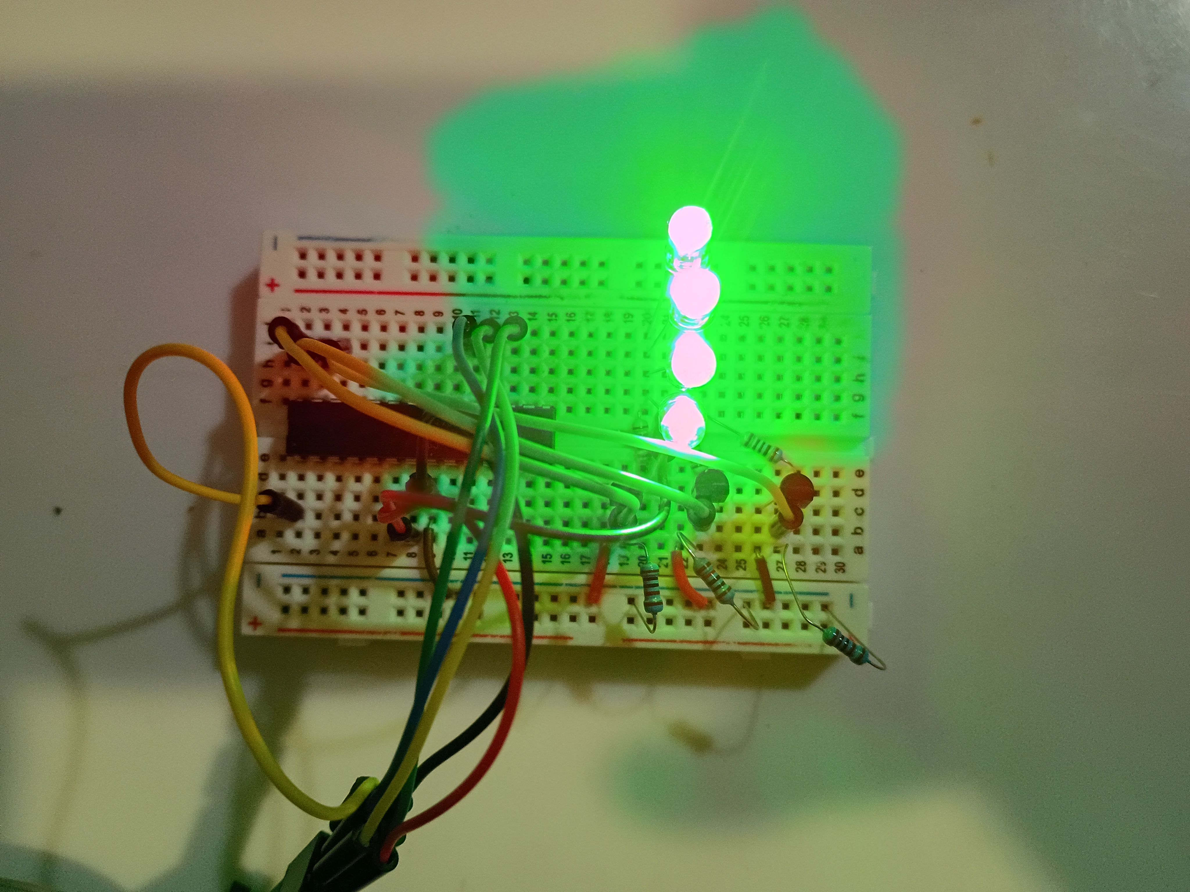
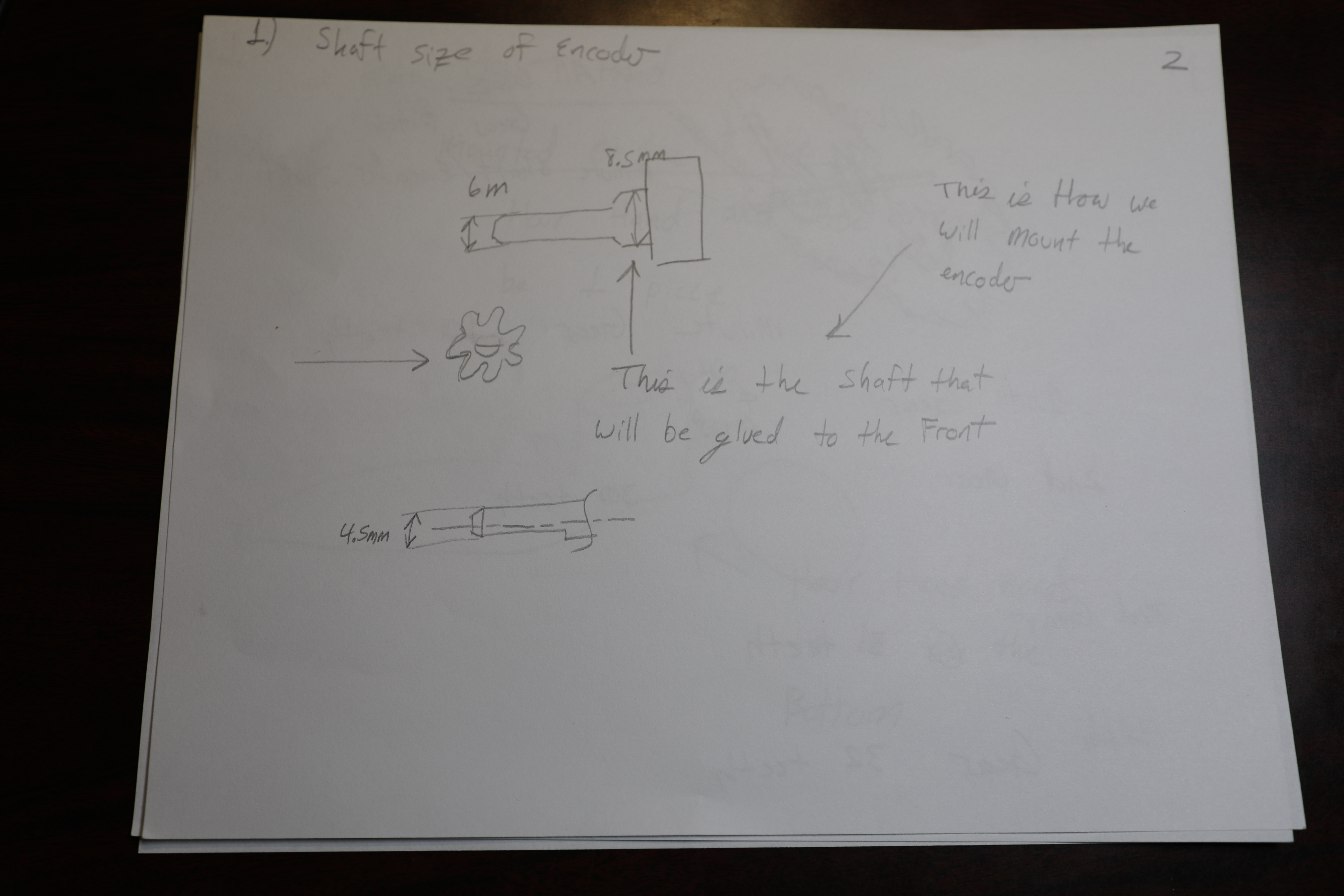
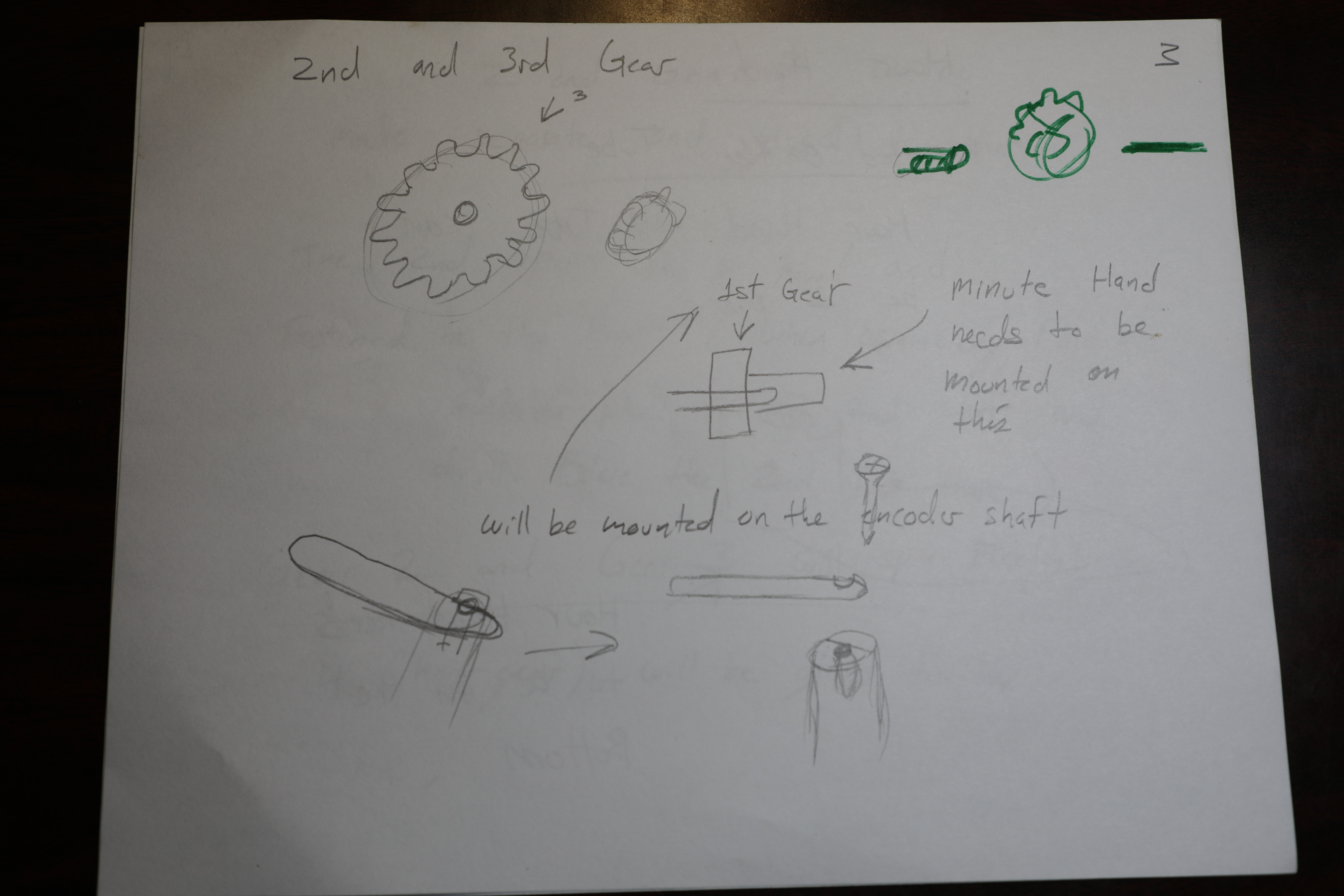
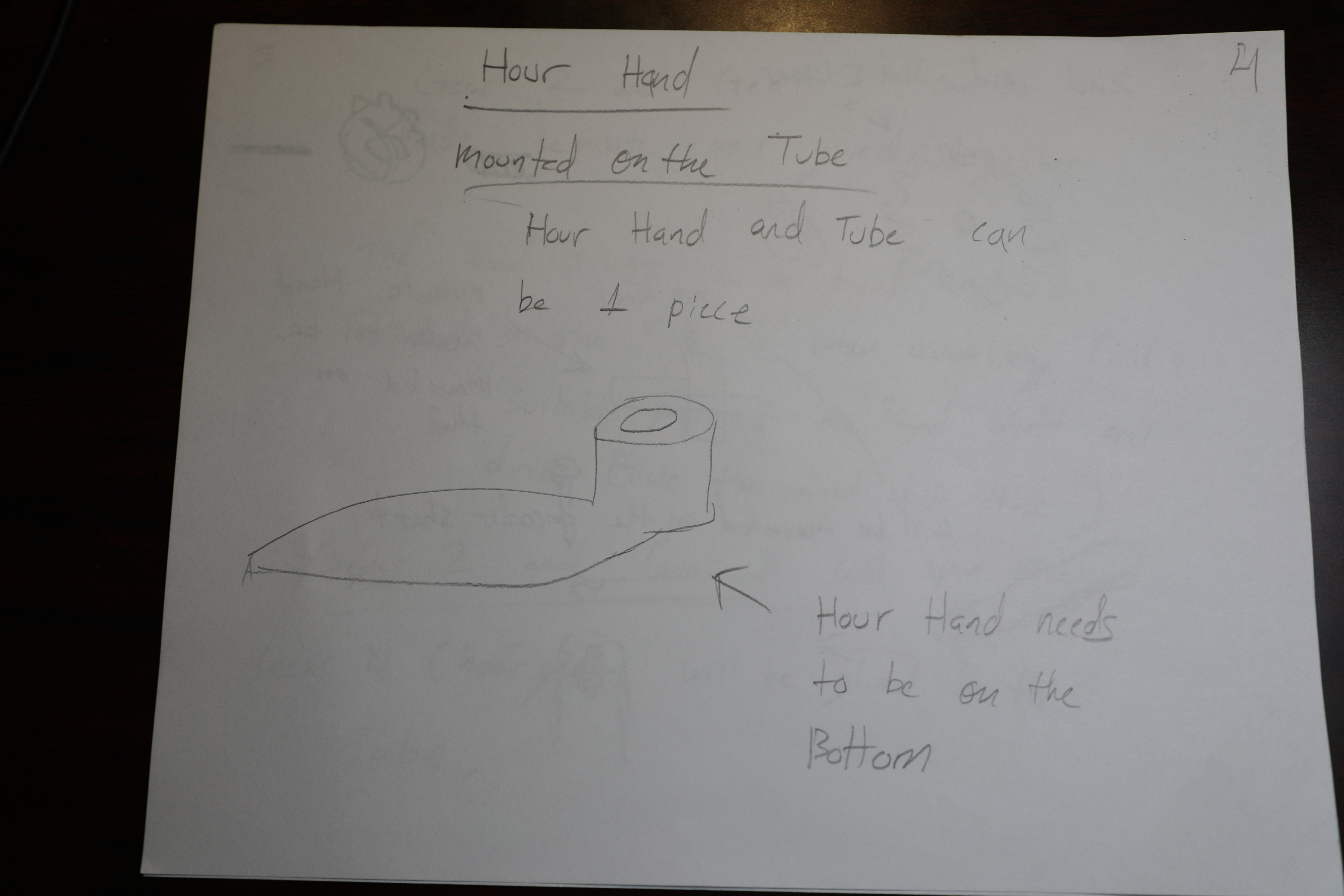
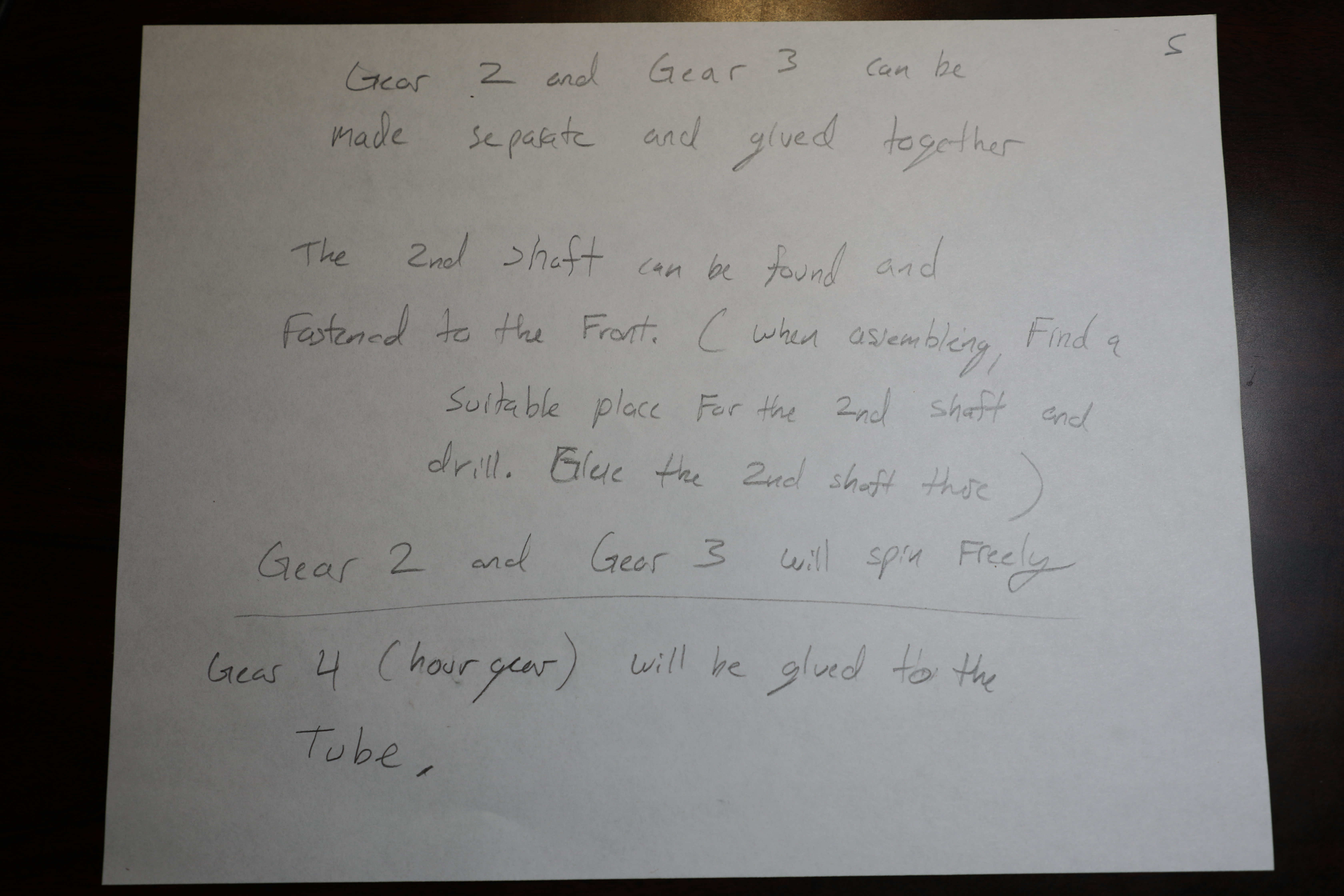
Over the past several days, there was a major effort to complete the CAD for the MM1 Minute hand gears.
Printed several gear components. Manufacturing recommendation is to make the hole in the hour drive gear all the way thru the part and increase the inner diameter slightly (0.1mm) for better clearance with the minute shaft. Components were assembled and functionality was tested successfully. 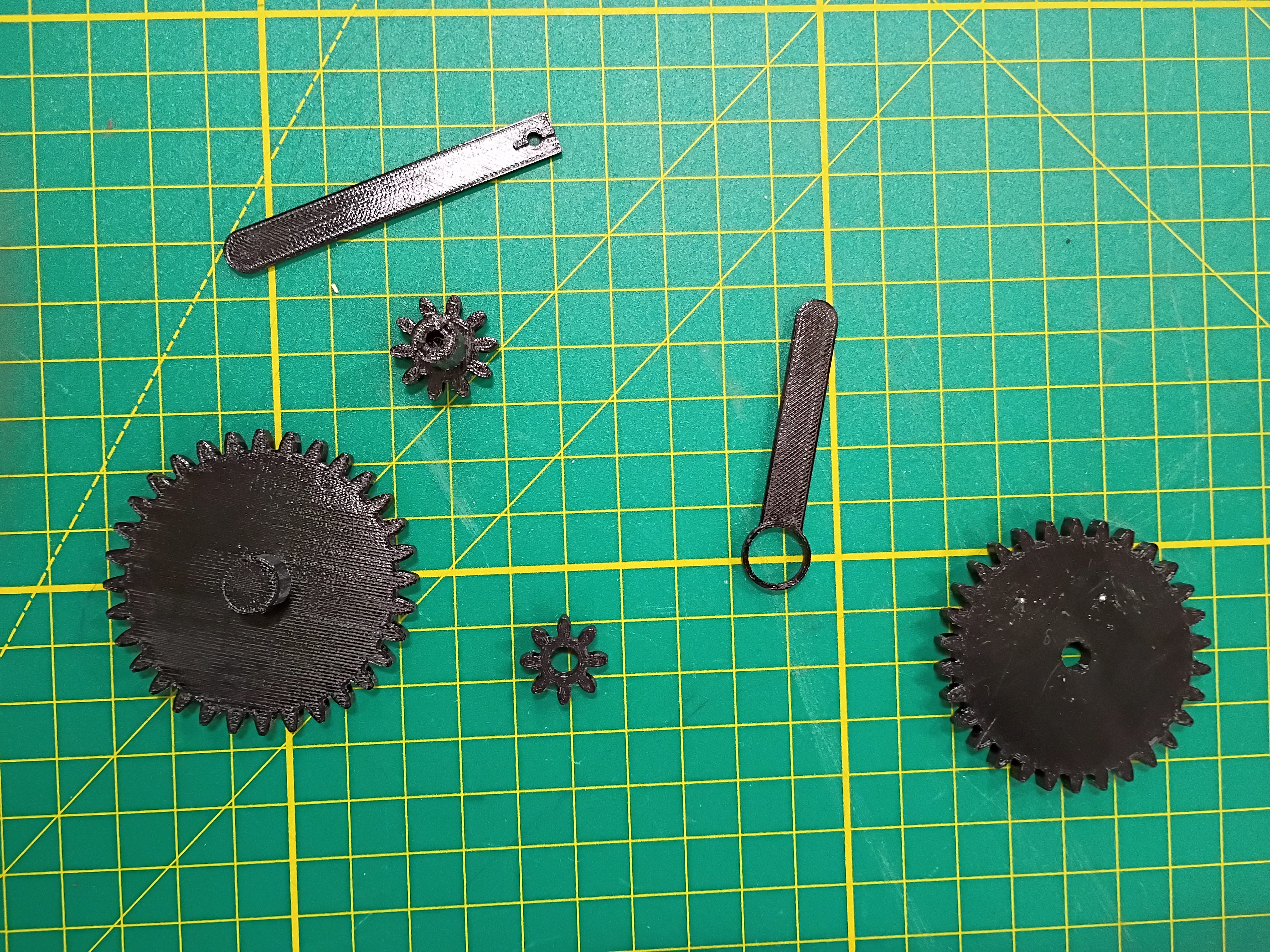
Laser cut 3mm acrylic bottom panel (30% speed, 100% power/current, 45W, only slightly caught fire). Countersunk holes for M3 screws (tendency to shatter, will not do again). Did a dry fit with the rest of the box. Continued to solder more components. 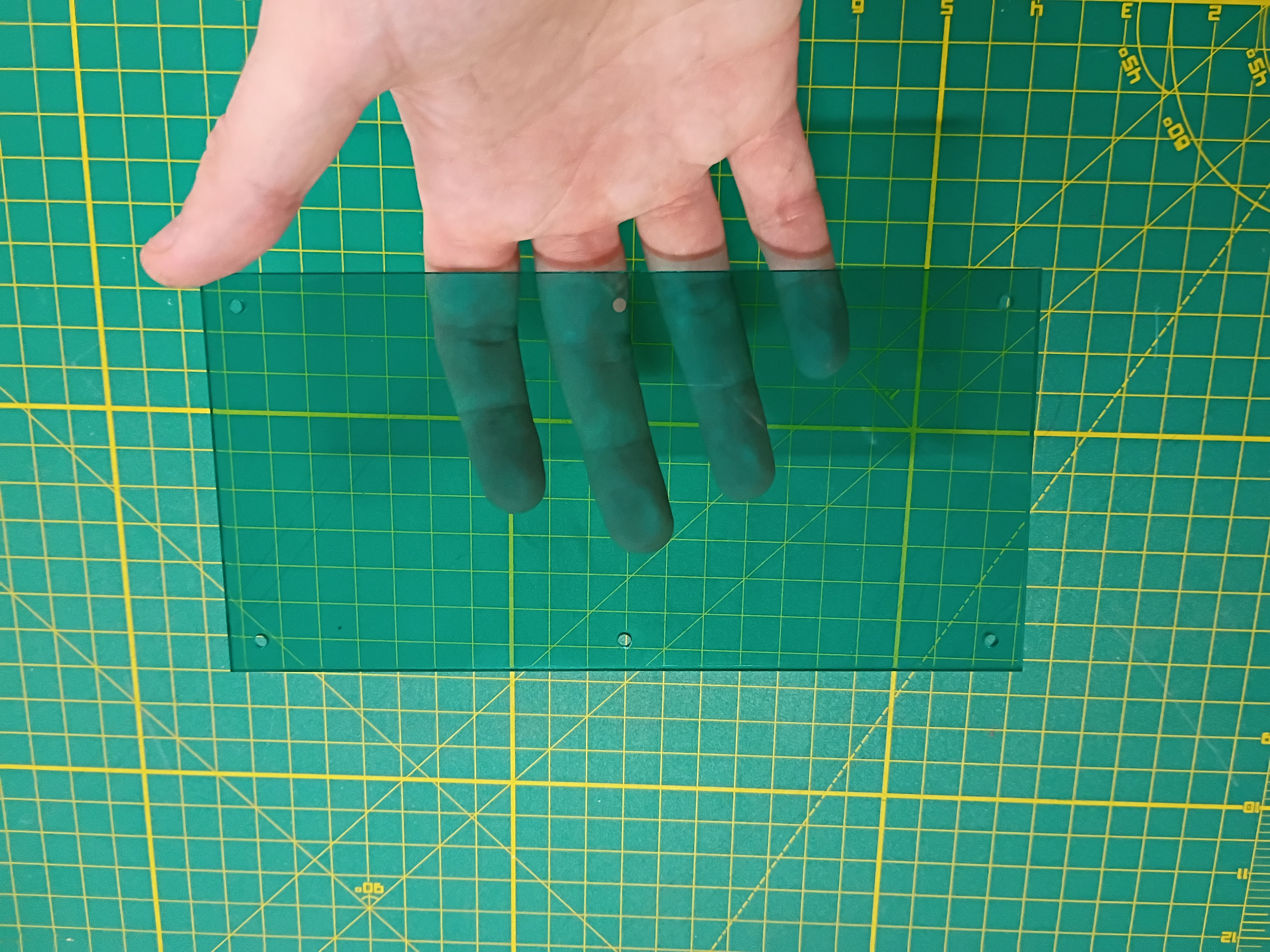
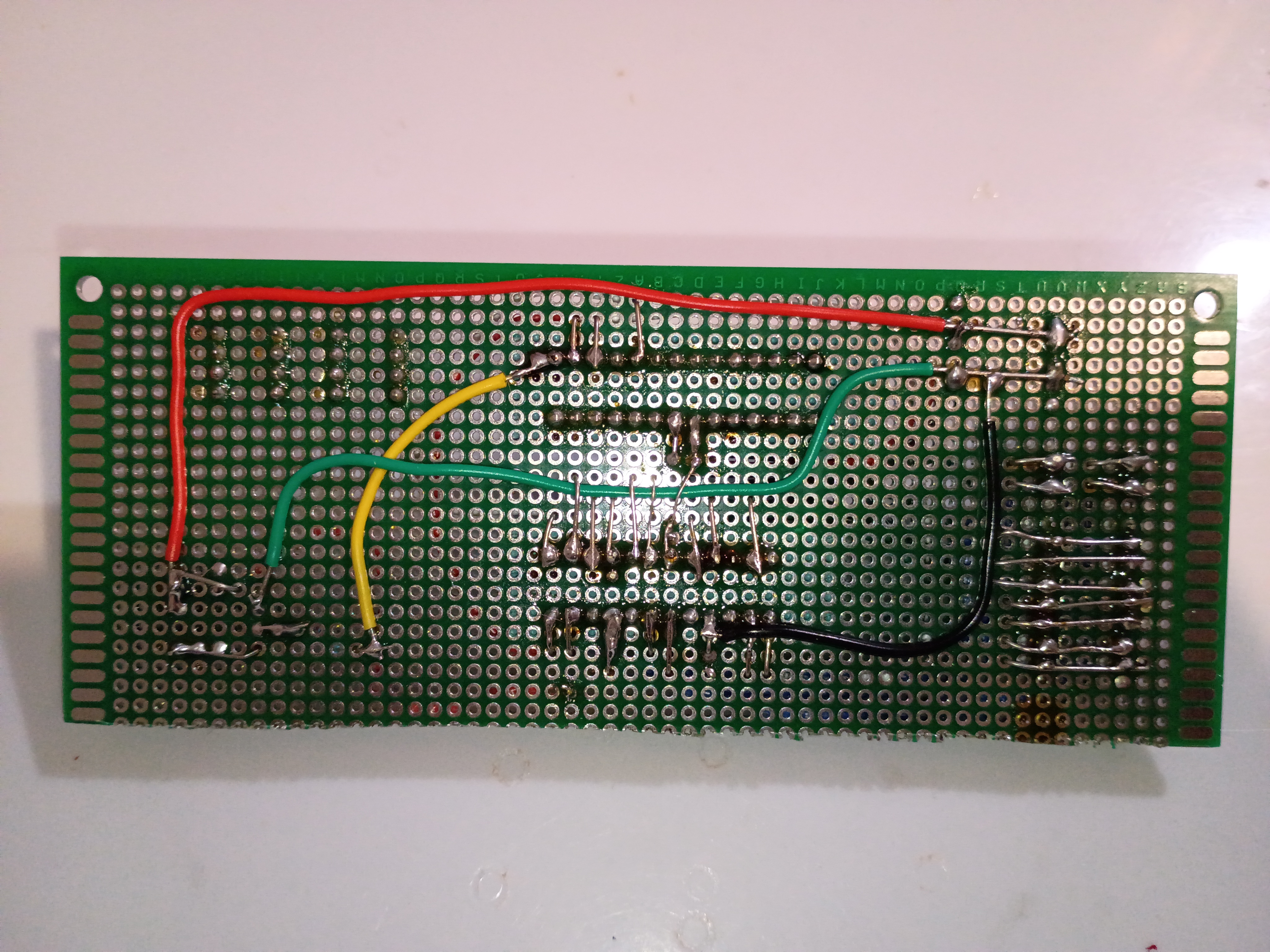
Cut perfboard with hacksaw and soldered several components. 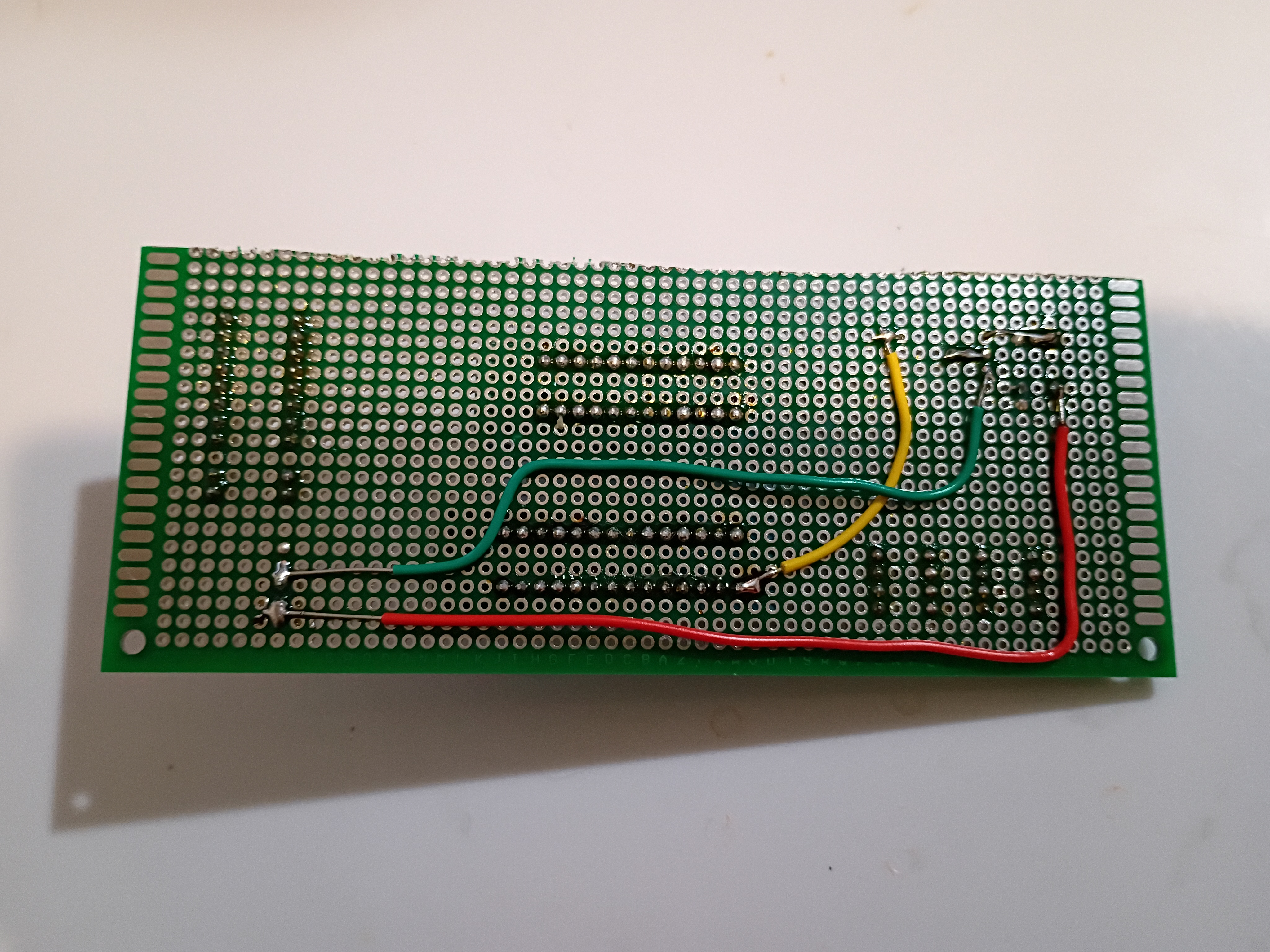
Got buzzer jingles and random integers working on Atmega328P using this C code to scare my cat.
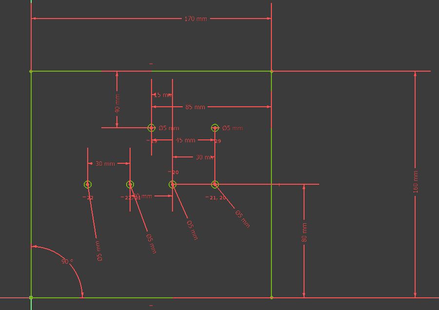
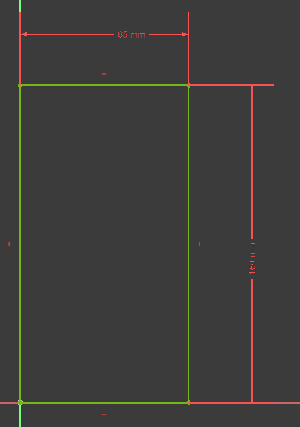
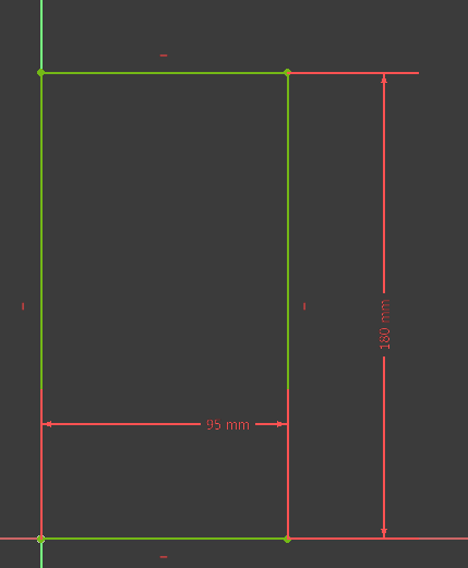
Yesterday, Plans were sketched out for the Design of the Minute hand and the hour hand and the corresponding gears. Such plans are pictured below, 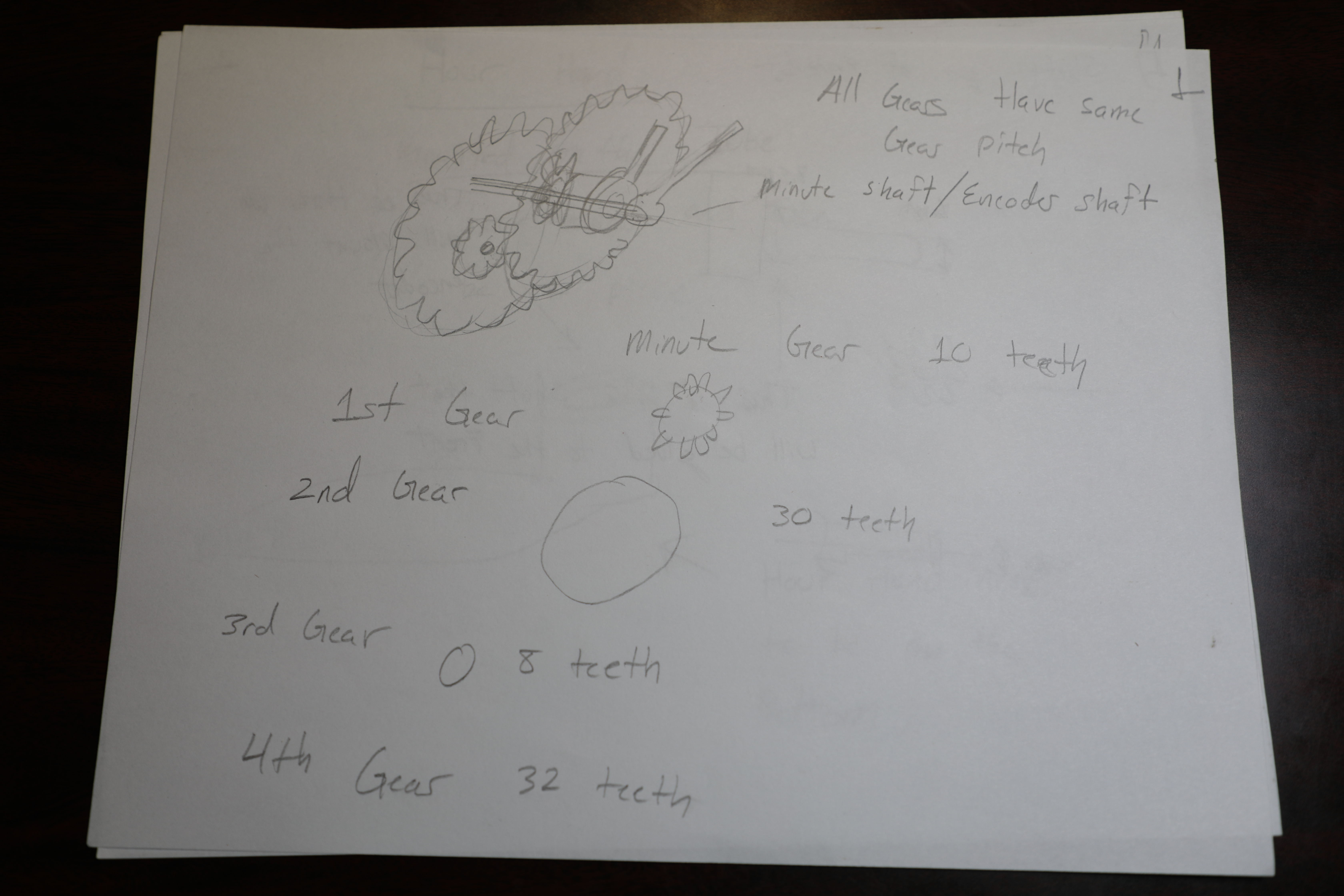
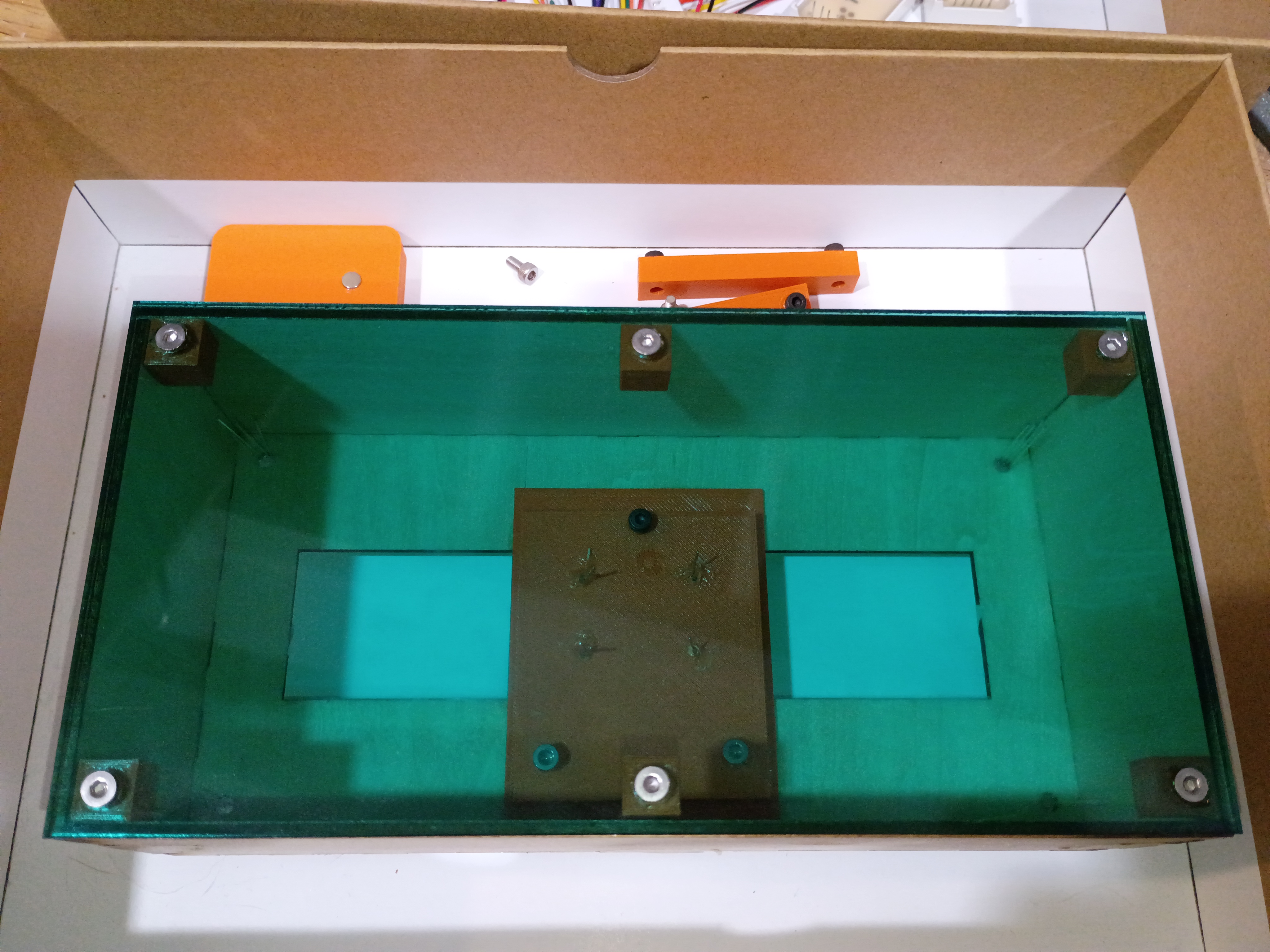
Printed additional mounting components and installed M3x4x5 heat-set inserts. One trick is to set them 75% in and then flip the part over and press it into the table; that gives the best surface finish. Installed reed switches and central chassis onto underside of box surface. Installed small magnet into plastic block for testing purposes only. 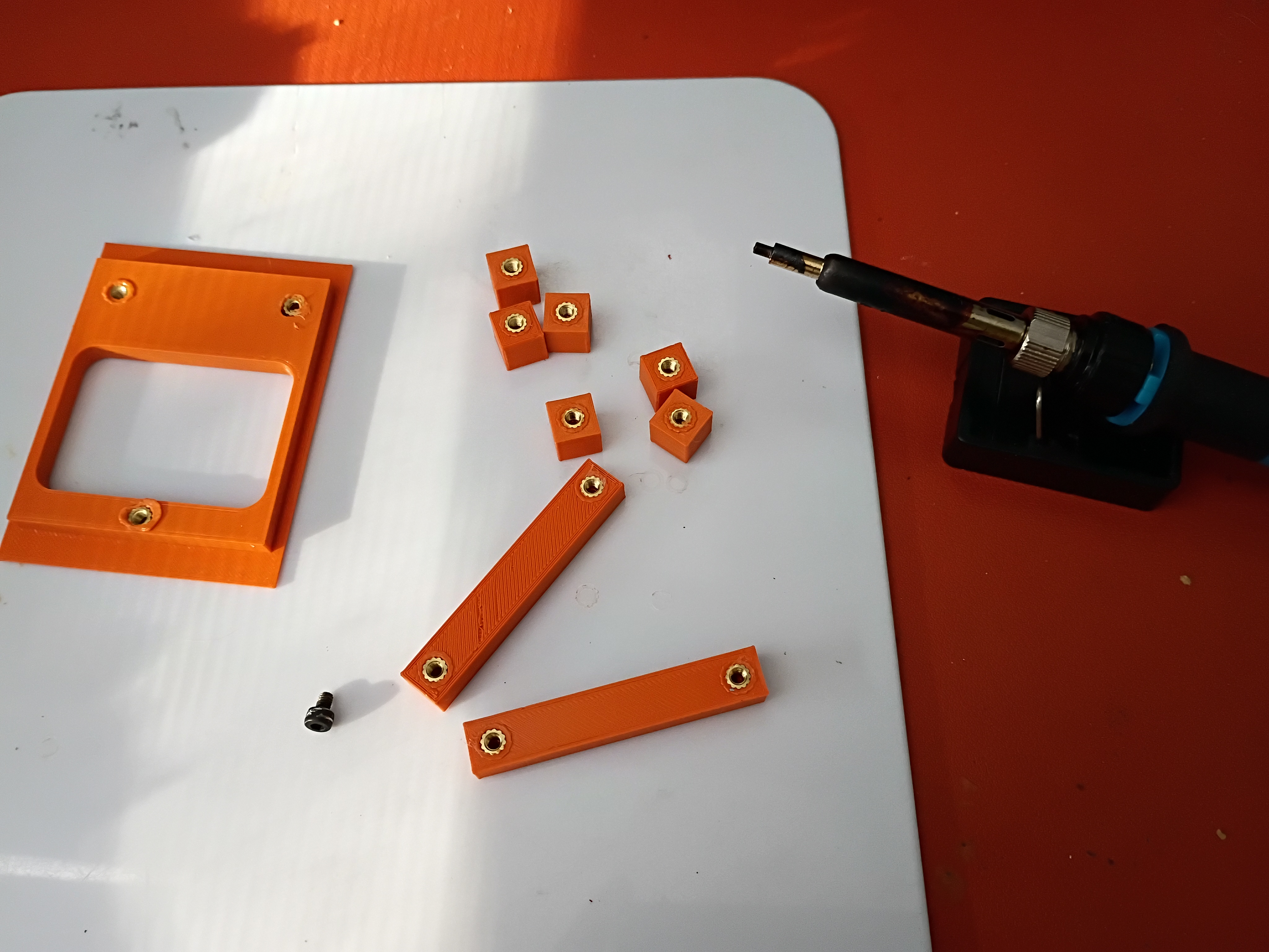
Continued to model assembly and began printing mounting components. 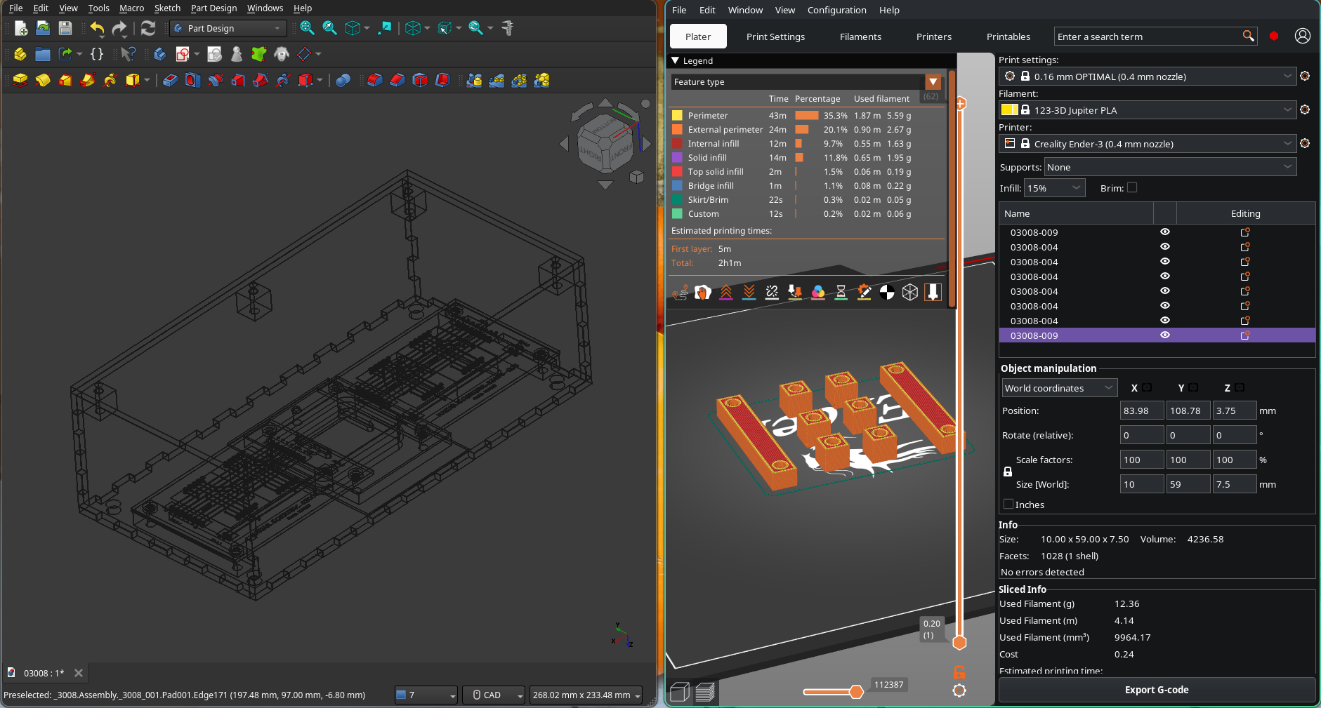
Mocked up removable reed switch holder and partial PCB support assembly. 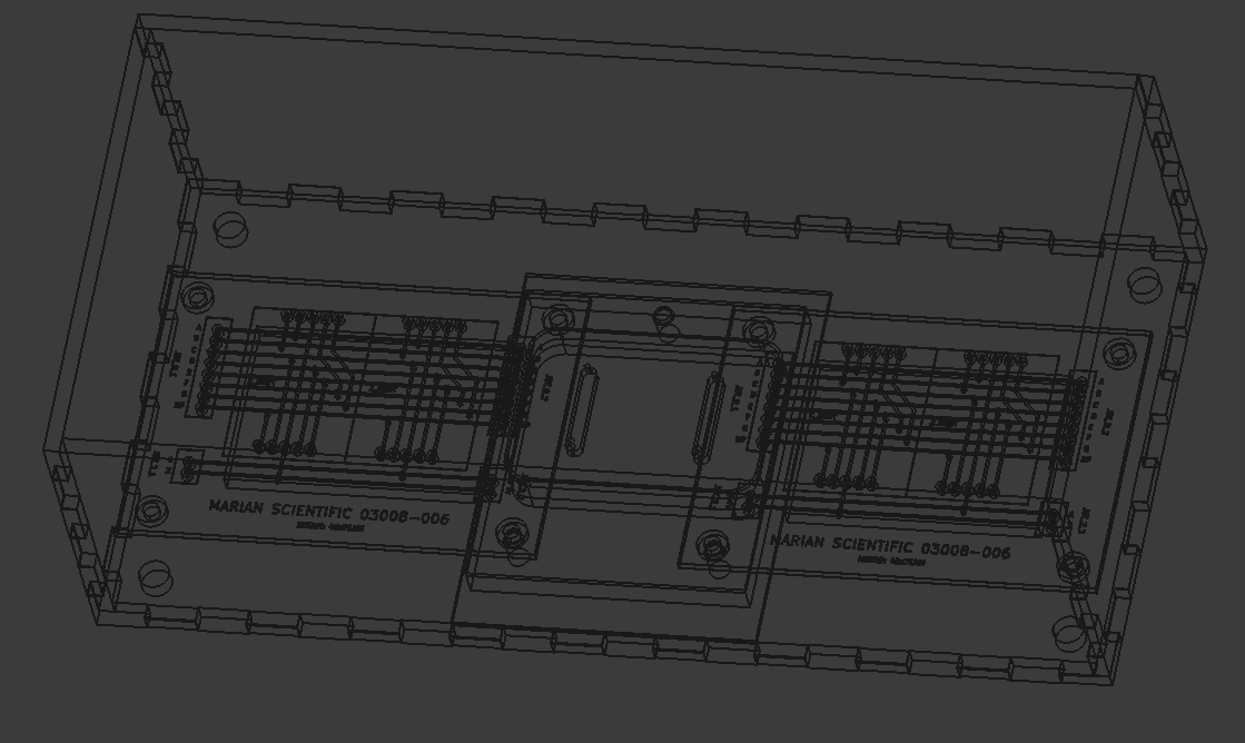
Several plywood panels were laser cut. 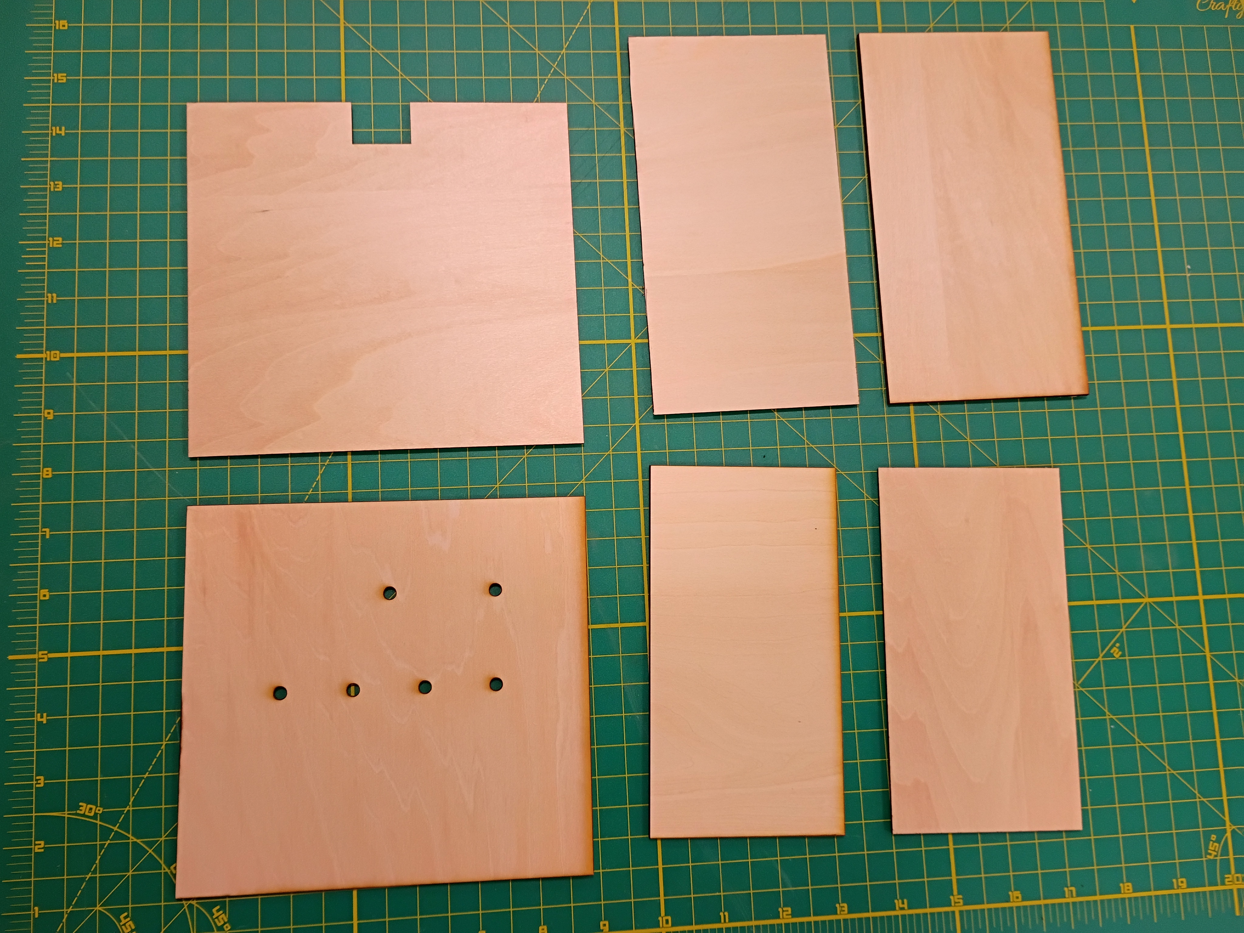
Made a rough sketch of the planning for the electronics encasement of MM1 Minute hand. 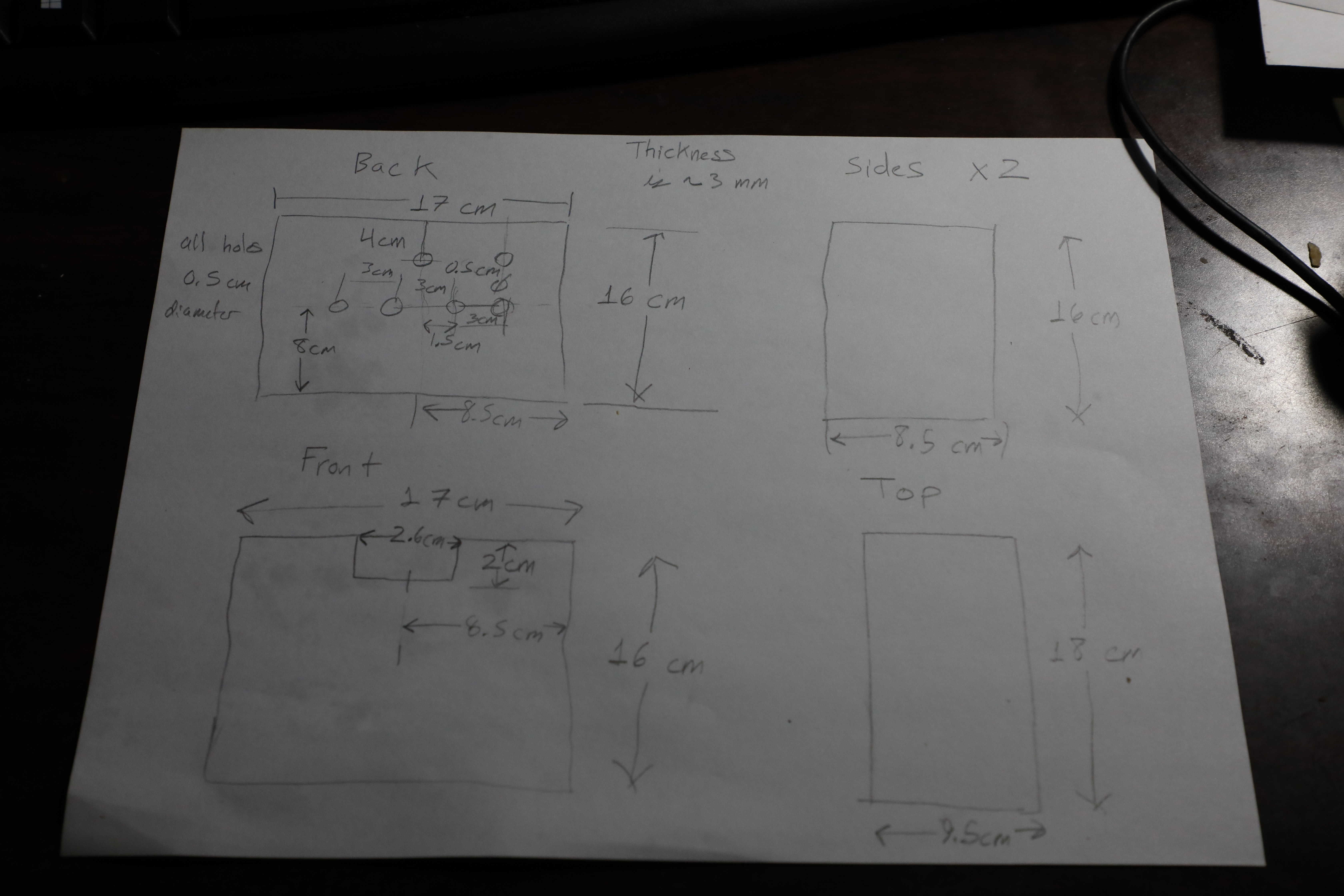
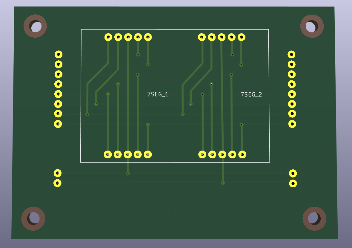
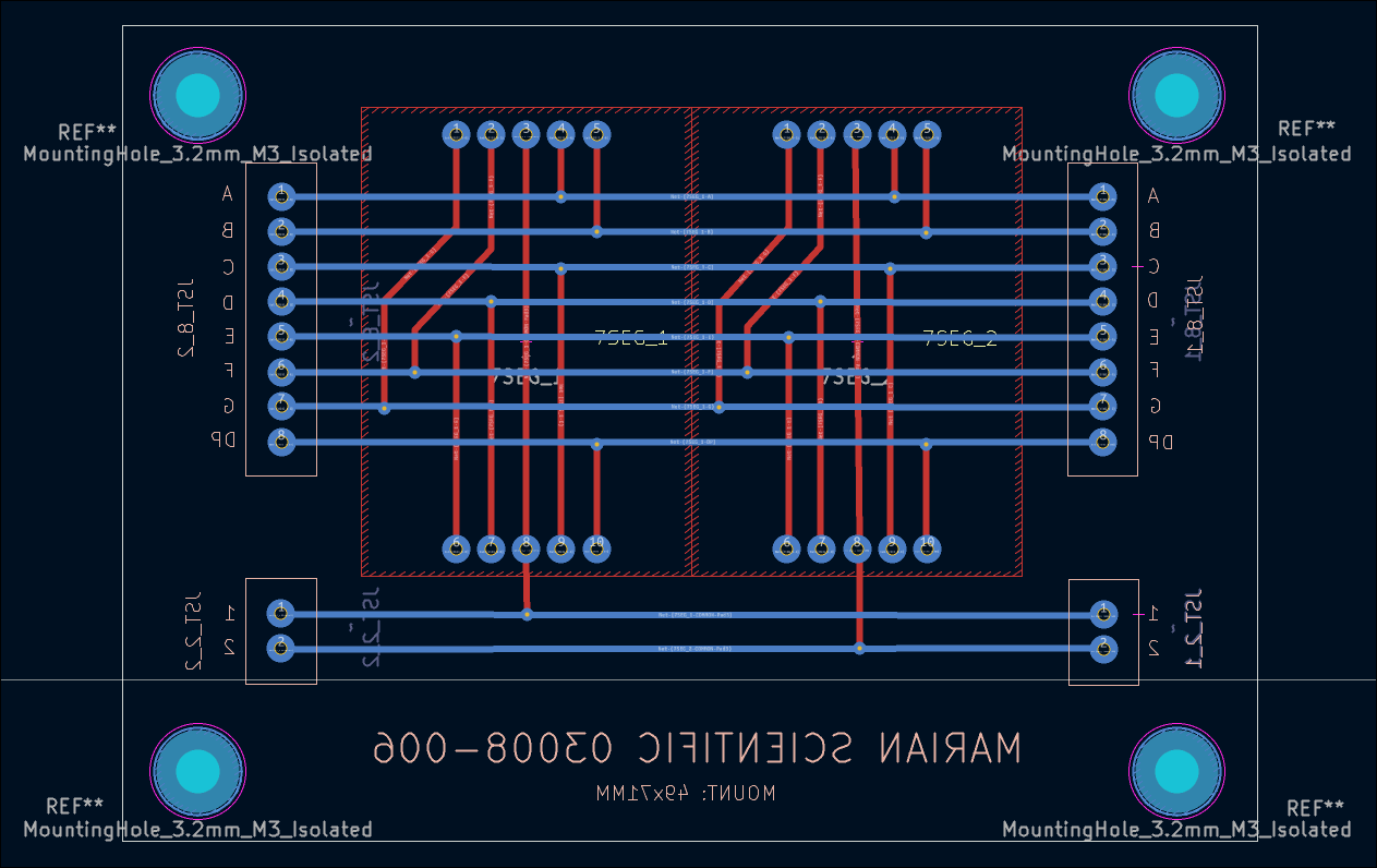
Designed (KiCad) and ordered PCBs (DKRed) to break out sets of 2x 7-segment displays to JST connectors. Cost per board was 11 dollars shipped, made in USA, to arrive in 10 days. Price seems mostly to do with board size. Decided not to expedite the shipping. 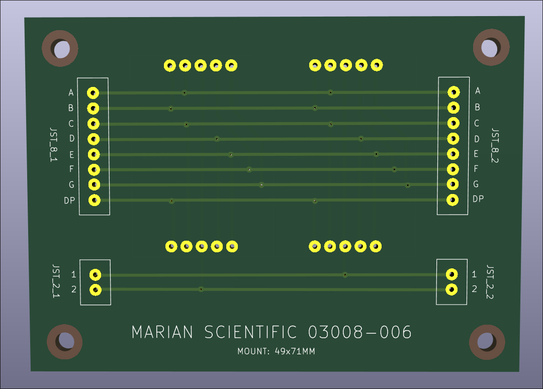
I conducted a preliminary fitment test of most of the electronic components in the box. I determined that getting small custom PCBs produced will drastically simplify the wiring and keep the box contents neat and robust. 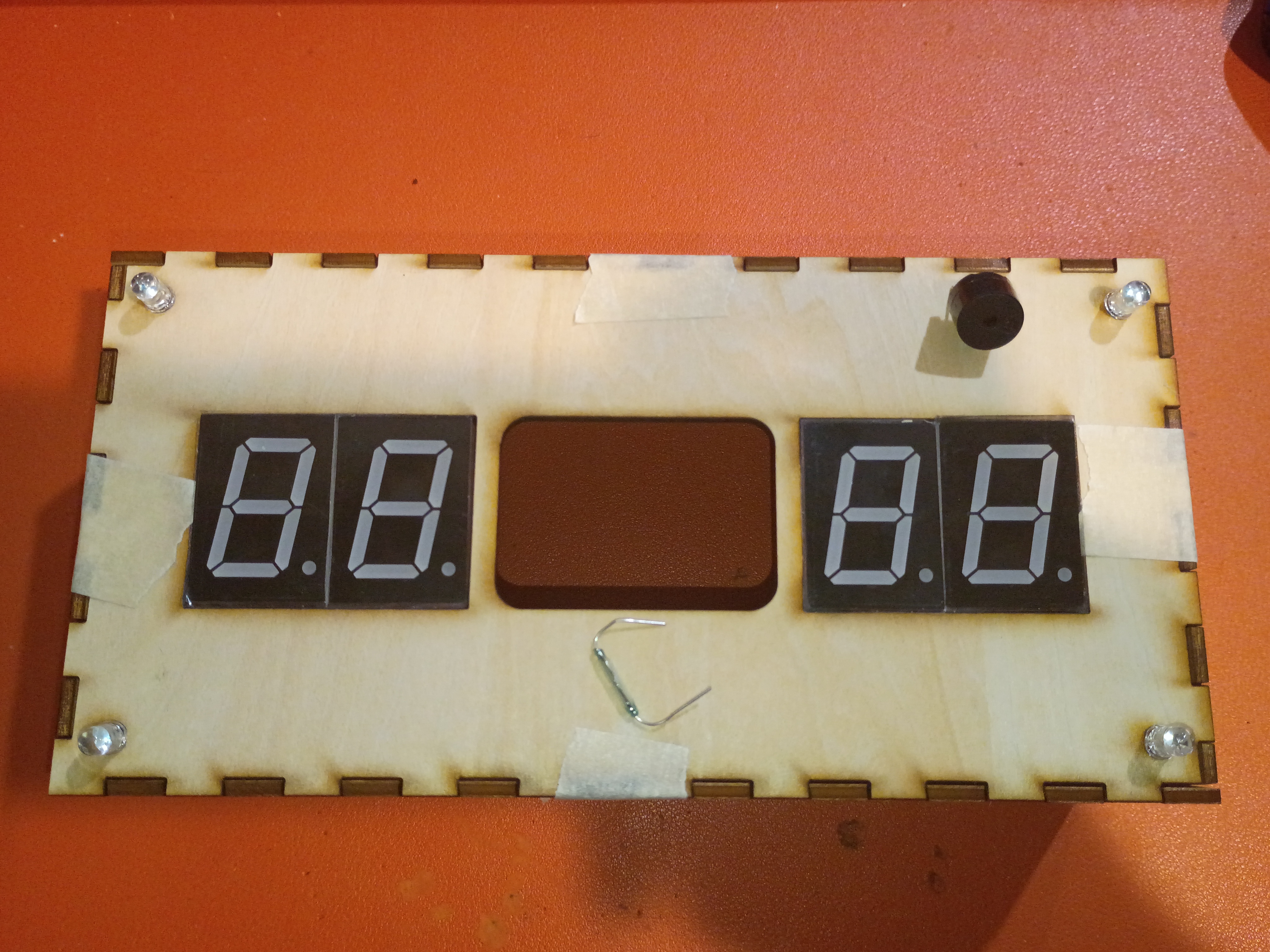
Laser cut around 30 finger-spacers. 20% power 20% current are decent settings for engraving the surface of plywood. Customer was satisfied. 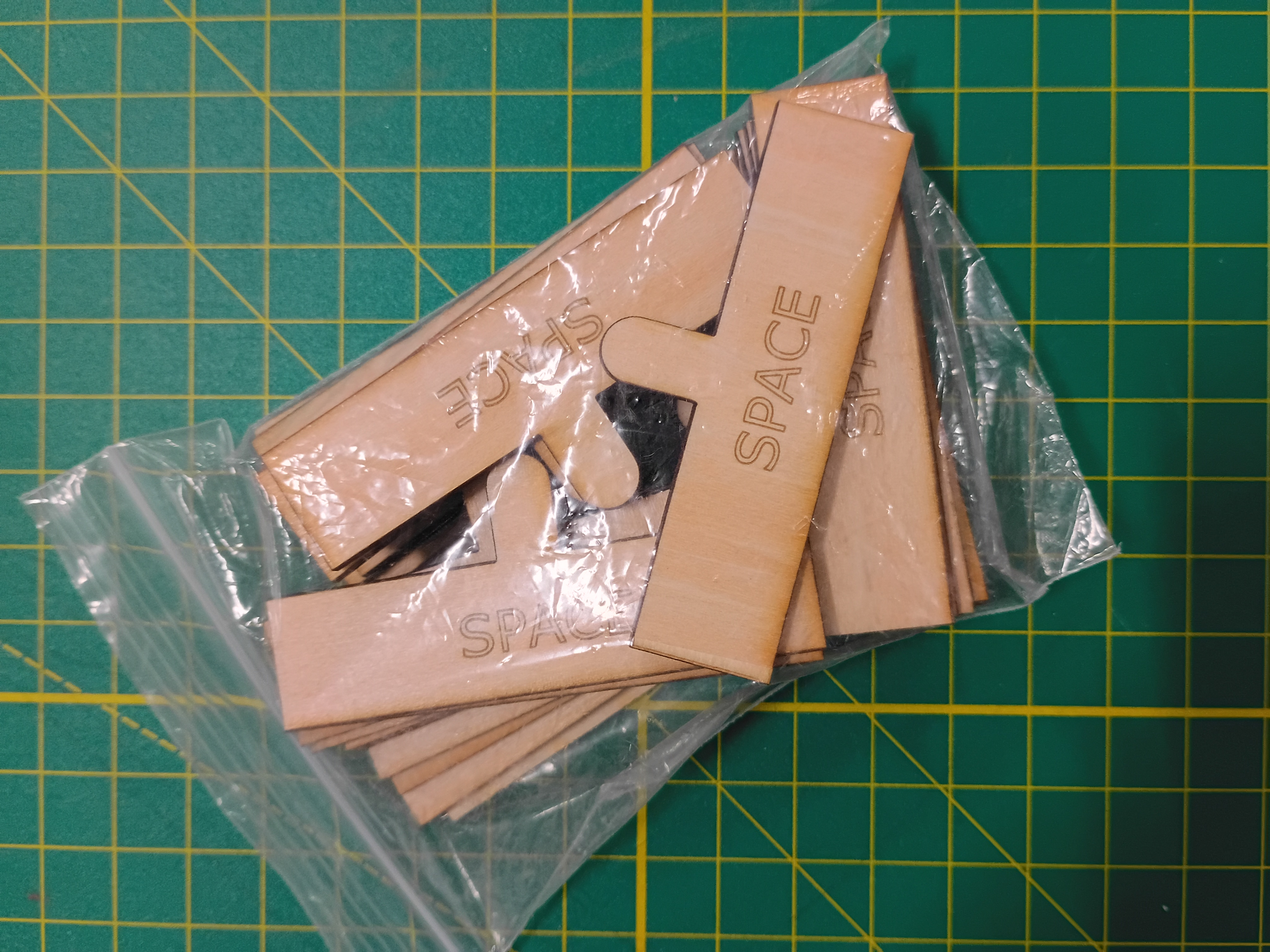
Most of draft box laser cut from 1/8-inch plywood with 3x10mm rectangular jagged edges. 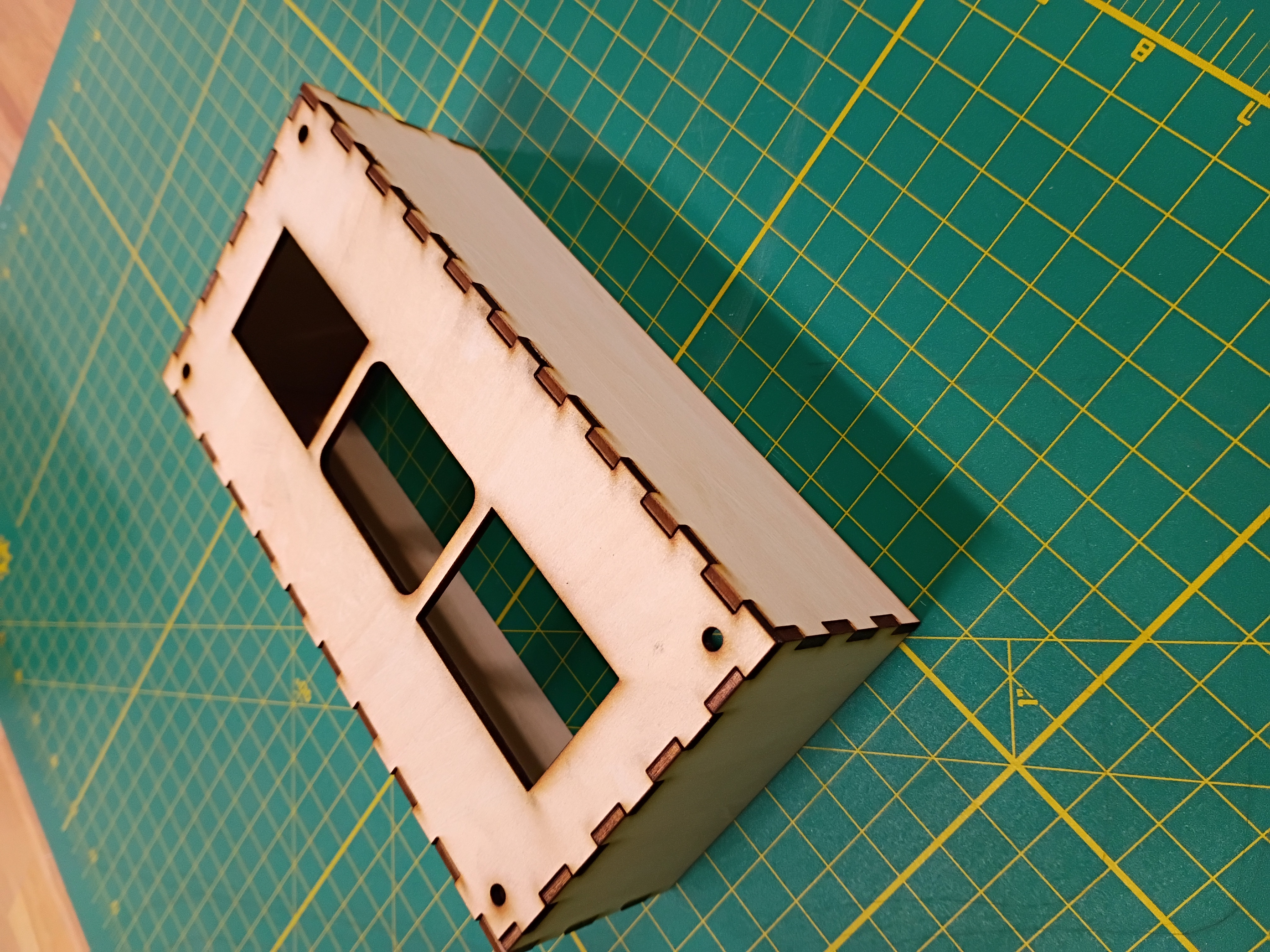
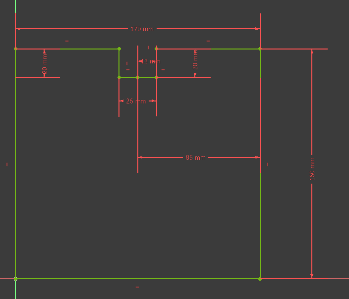
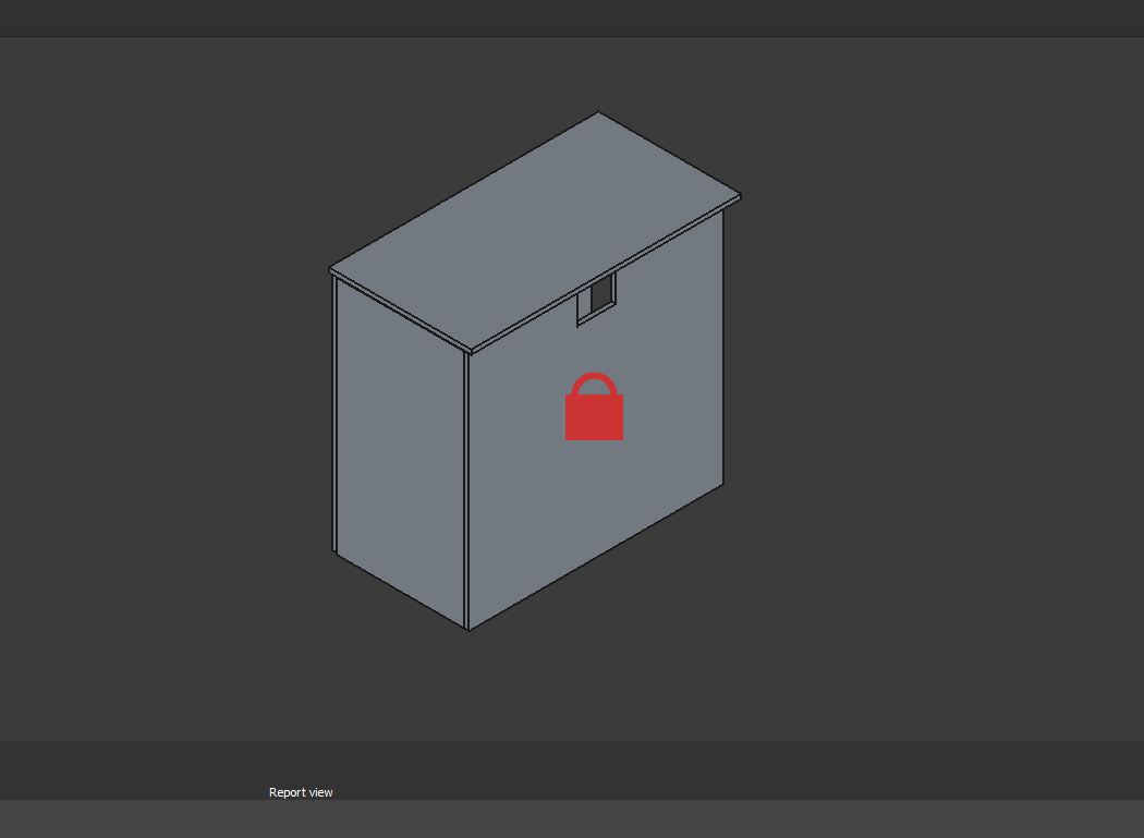
I wrapped up the 3D and laser cut definition for the box sides. 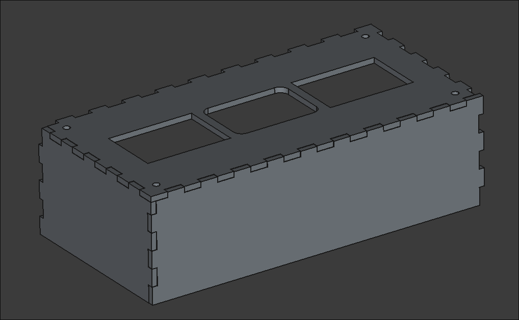
Received Packages yesterday for Testing and construction of the project. 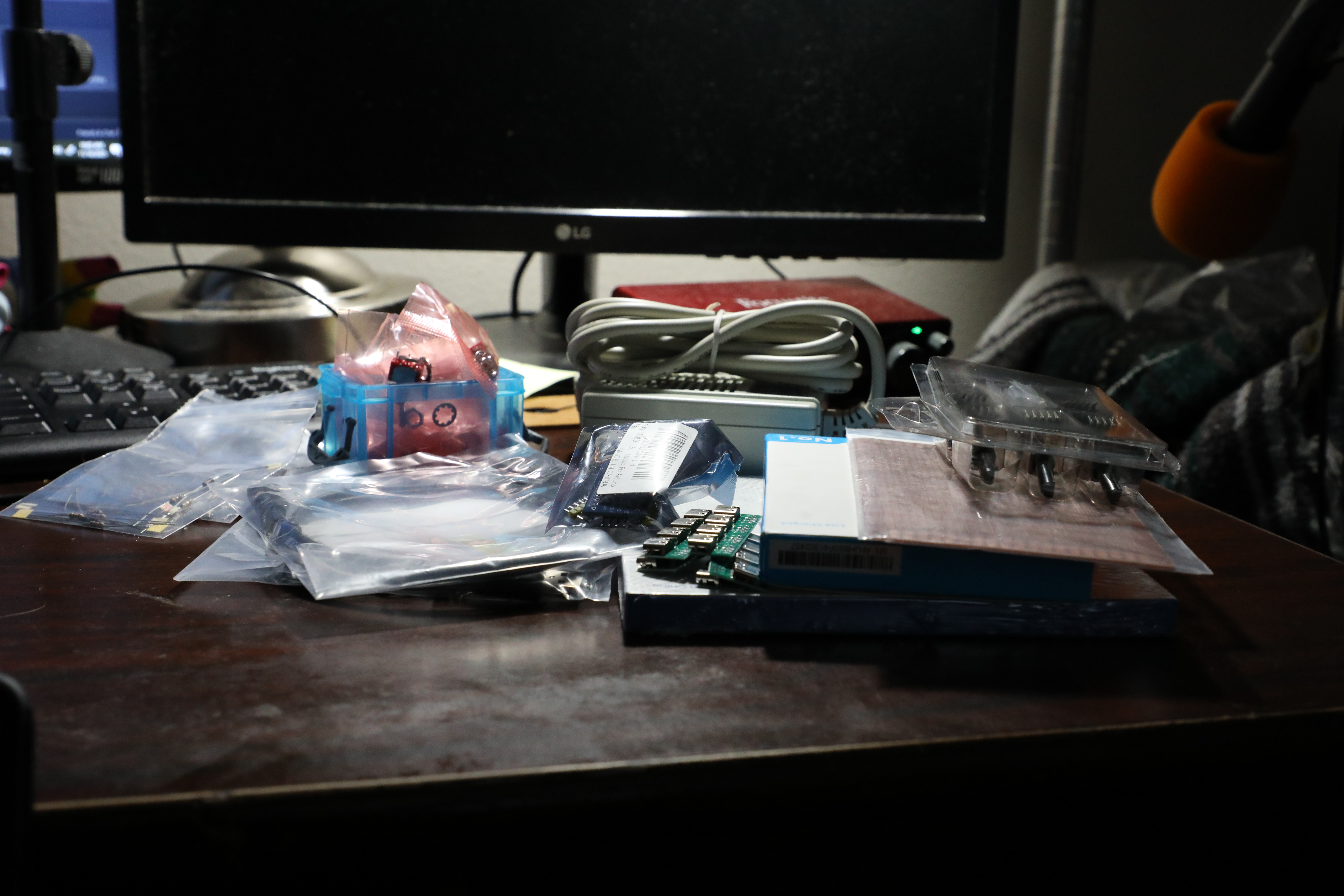
Created an SVG path for a finger-spacer tool to be laser cut. It helps children leave a space between words when they write. 
I mocked up a preliminary faceplate SVG to be laser cut. It has holes for the 7-segments, RGB LEDs & central block. 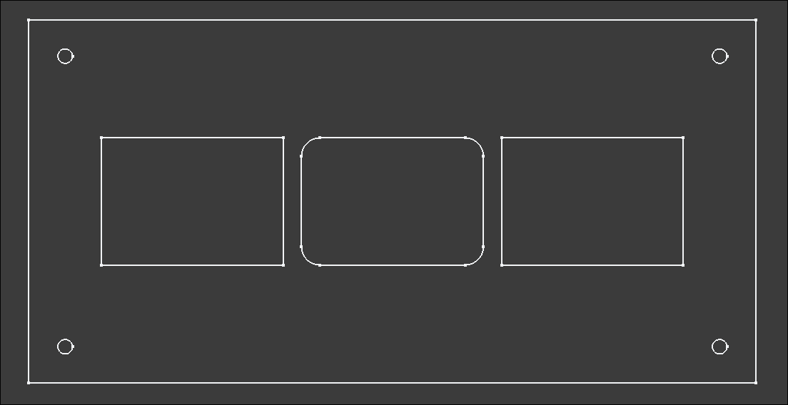
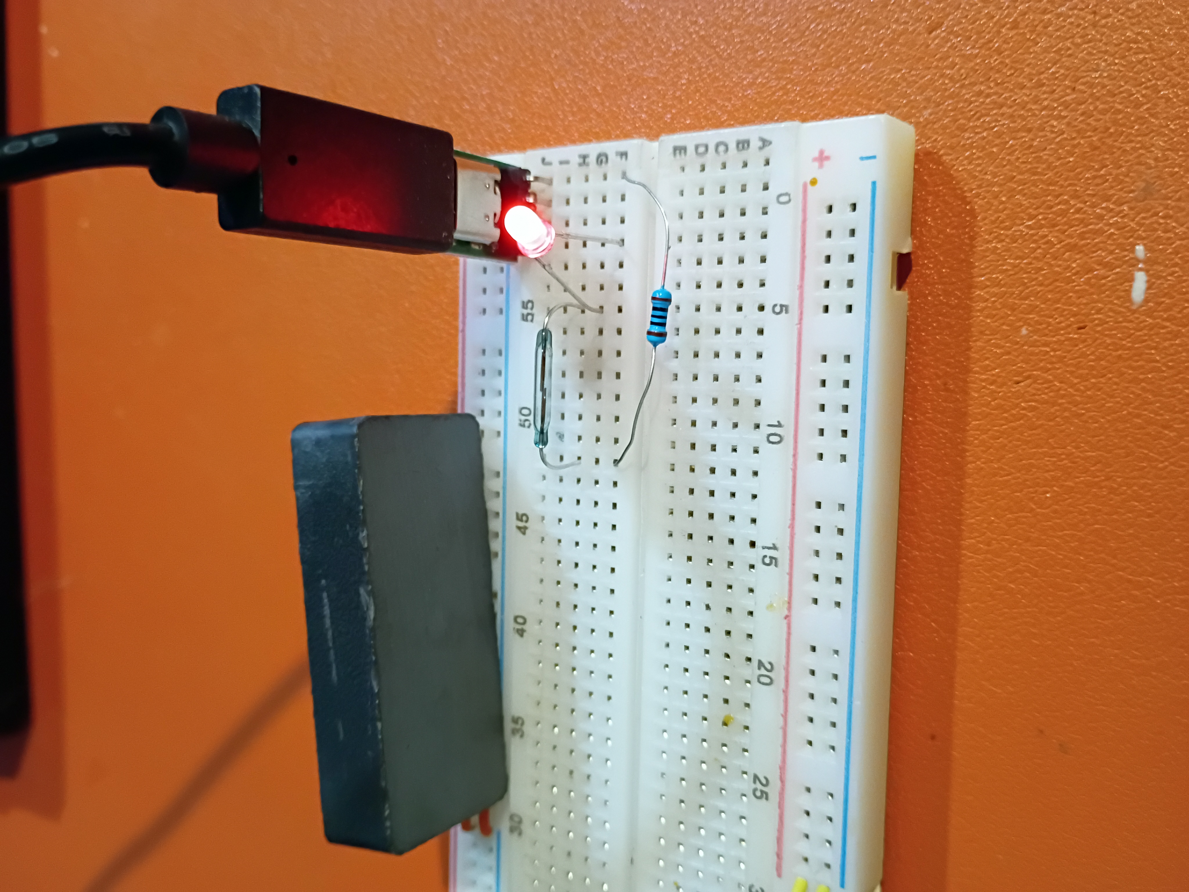
I also tested a USB-C power supply and a Reed switch as an alternative to the Hall effect sensor. It is extremely sensitive.
I updated the GitHub workflow and script to automatically create thumbnail images and added a shorthand for embedding & linking them, among other website formatting improvements.
I adapted the Atmega328P C code to control the 4x separate 7-segment displays.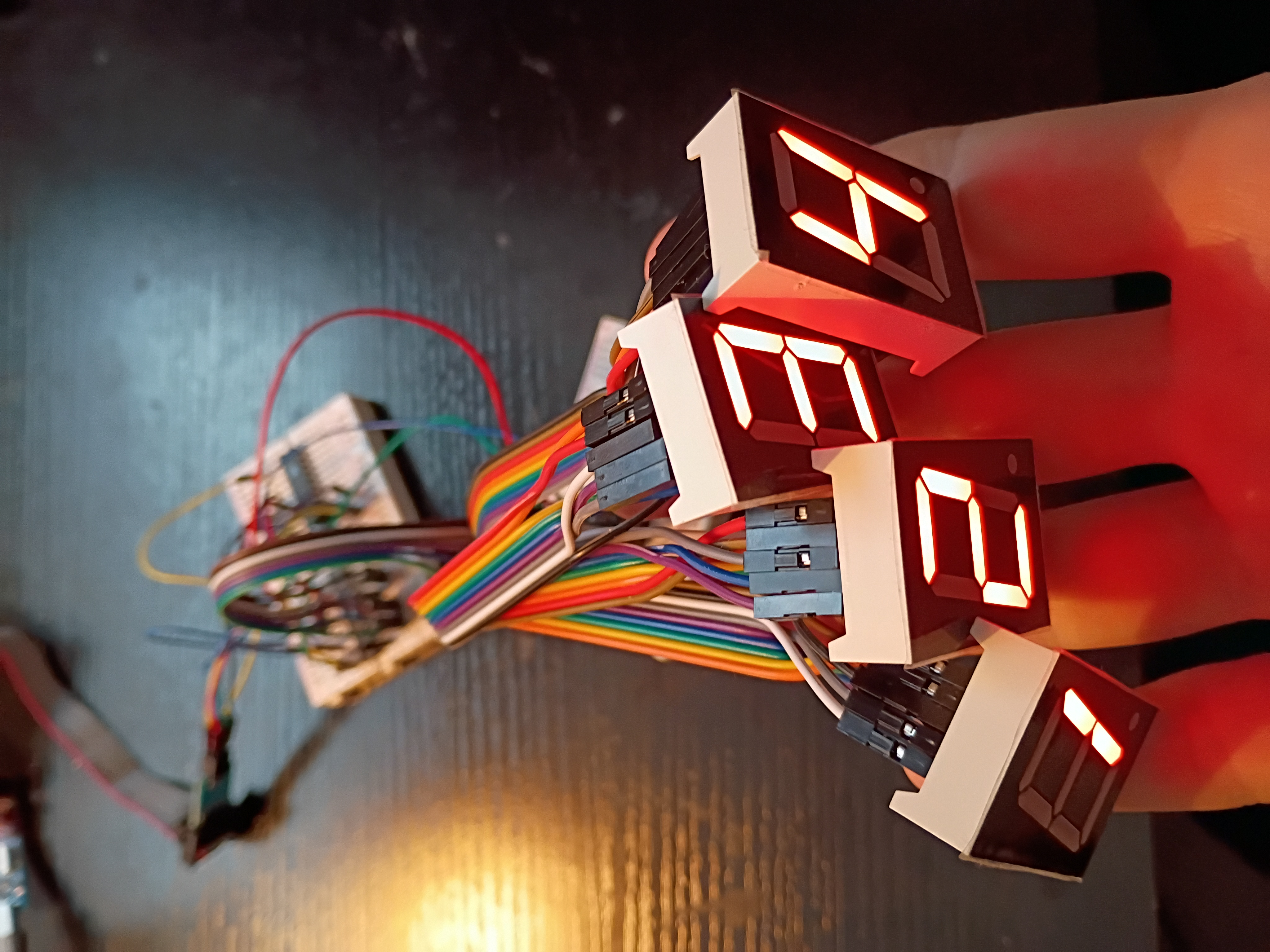
The Electrical Parts were accumulated in a list to order from Amazon and Mouser. The order was placed today November 13.
Researched More items for MM1 Minute Hand which include a portable power bank from Amazon. In addition Orders for a microcontroller and breadboards were also Researched.
researched Parts to order including: USB C cables, female USB C receiver, encoders, SPDT switches, Rechargeable Lead Acid Batteries, LiPo batteries.
I hooked up 4x 7-segment displays to the MAX7219 IC for testing tomorrow.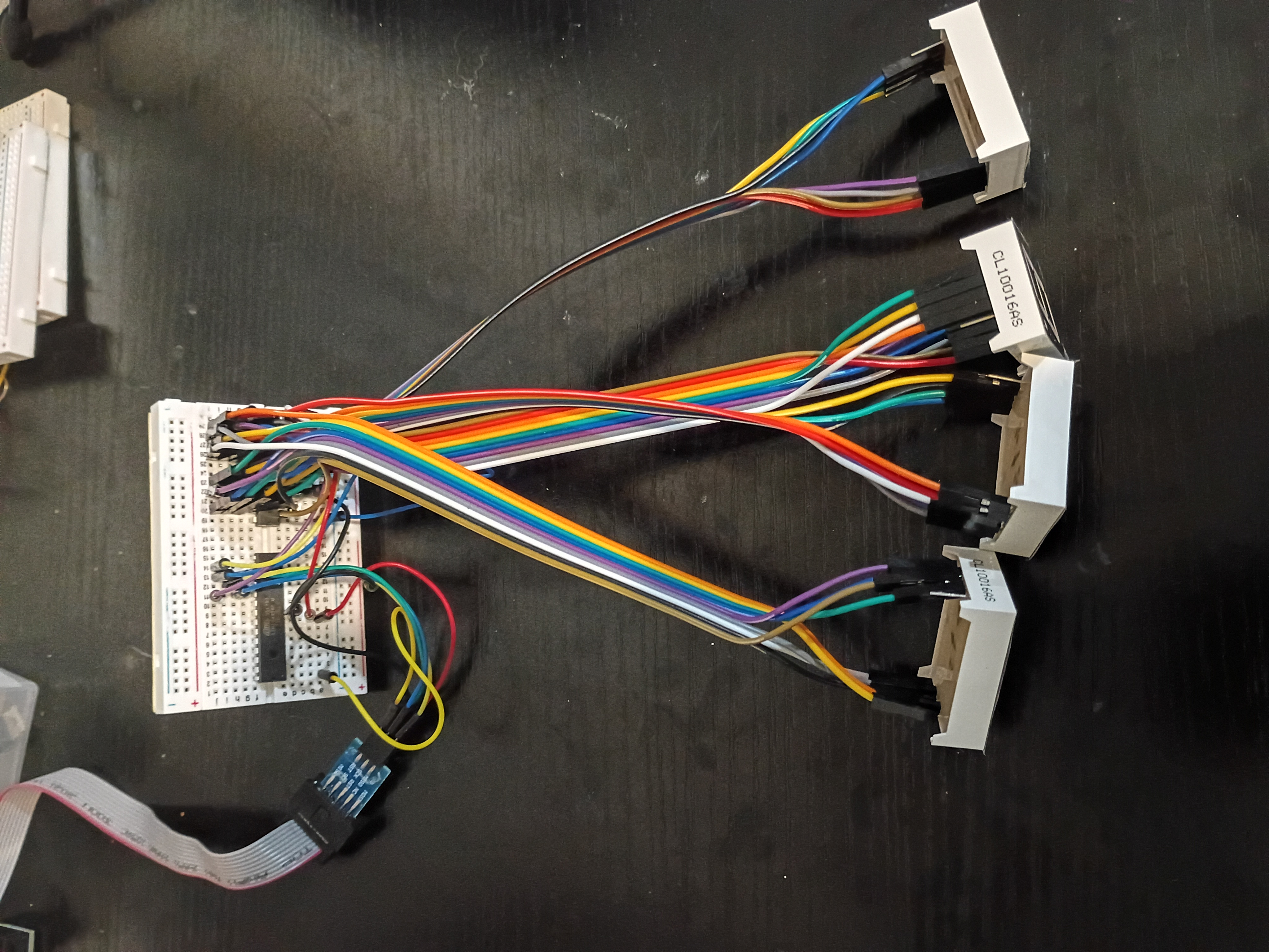
After much debugging (2 days), I realized I had the Rset resistor on the MAX7219 jumping to GND instead of 5V. I thought for sure it was supposed to go to GND. Either way, we have this Atmega328P C code to control a 7-segment display over what is essentially SPI.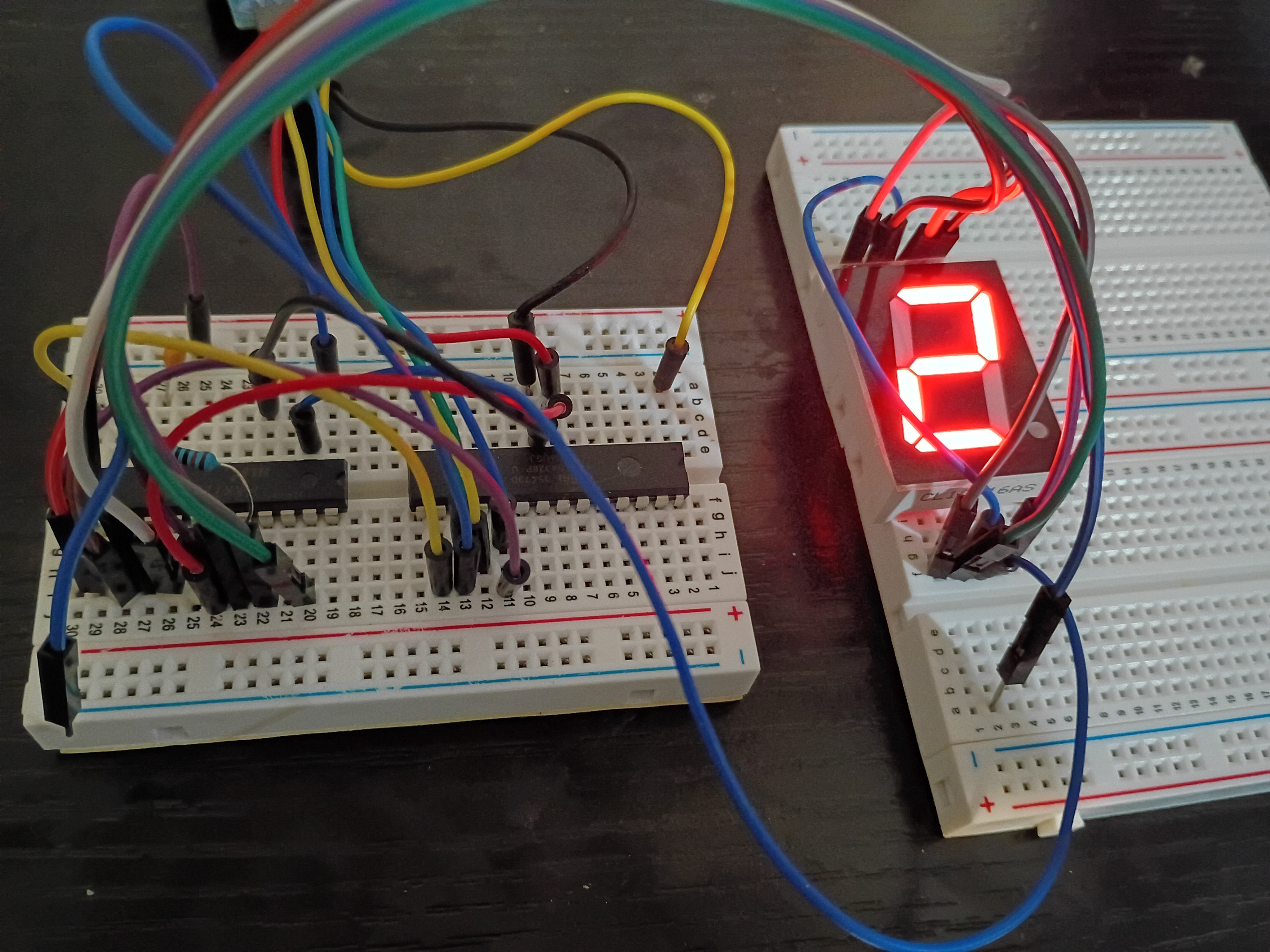
Learned the basics of FreeCAD to design parts for Minute Hand.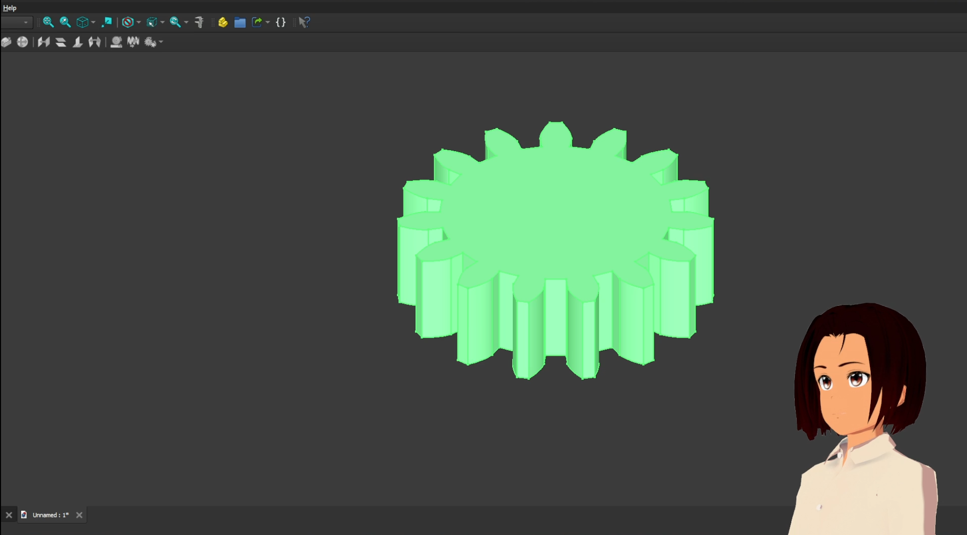
Got some exposure to laser cutting on the Muse3D at work. Made some personal engravings and tested various power setting and cut speeds. At 100% power even 100% speed is enough to cut thru 1/8-inch plywood.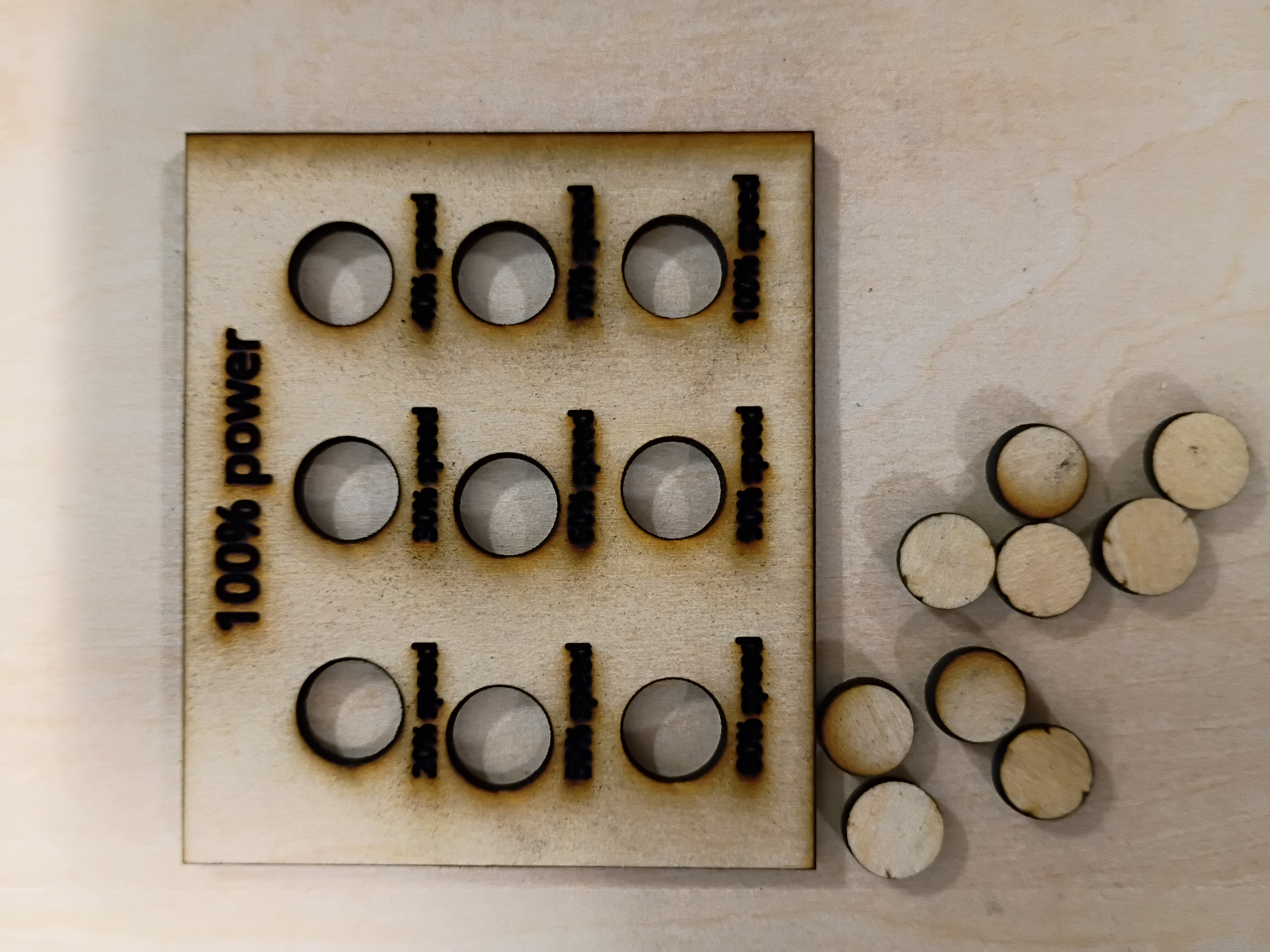
Bought Perf Board, resistors, and a Power Supply for the Main circuit.
I set up an automated GitHub workflow to generate these journal entry pages automatically and updated the construction script to handle an index page. More to come.
I attempted to implement a circuit to control a 7-segment display using the MAX7219 driver IC, but unfortunately my 7-segment displays are all common-anode, so they are not trivially compatible. While I source common-cathode ones, I tested a basic digit Hall-effect circuit using an LED.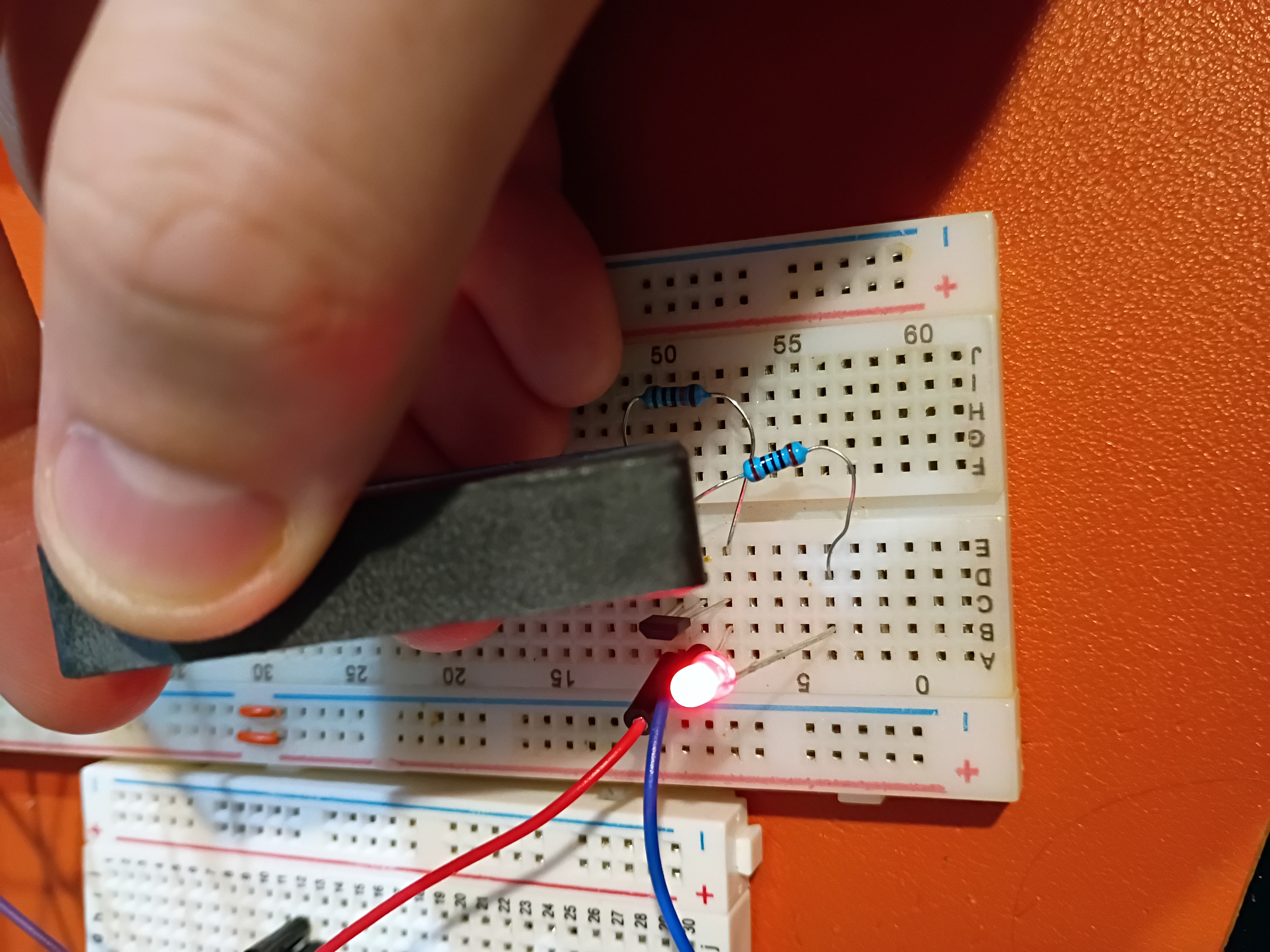
I tested control of an RGB LED with an Atmega328P here.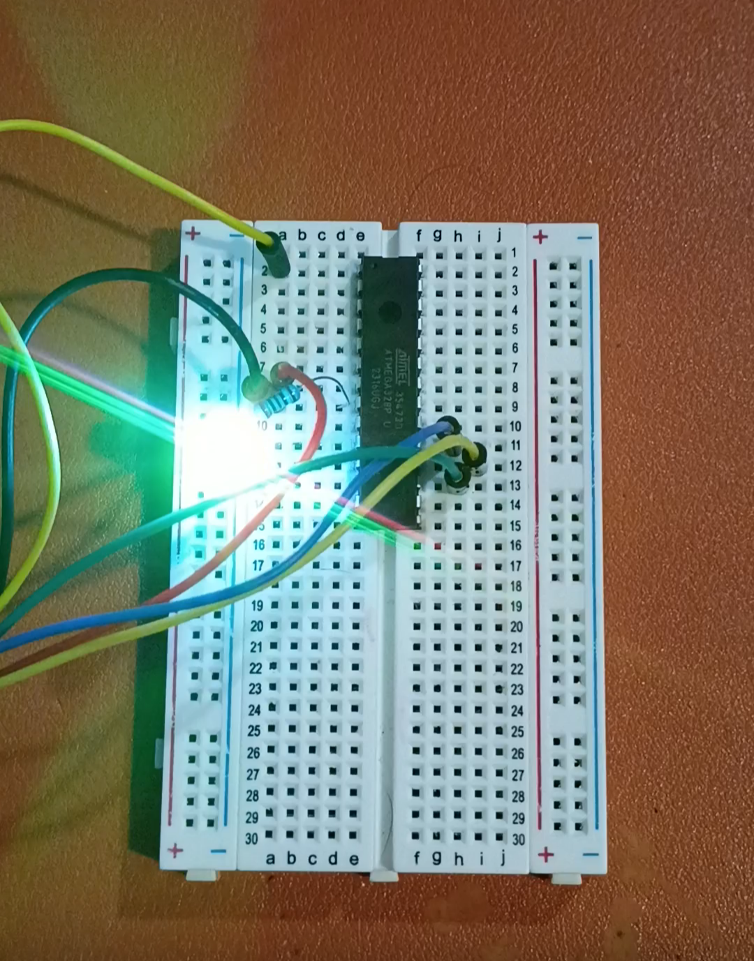